Bridge load rating – Beam with the import of internal forces
1 Model
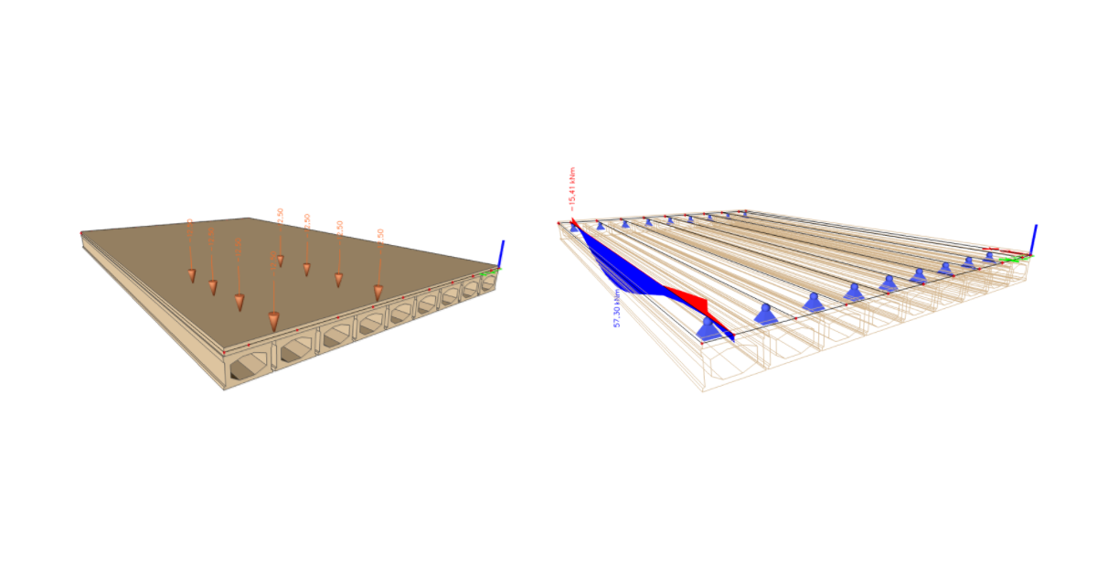
In this tutorial, you will work with an already prepared file containing a model of one prefabricated beam, which is part of a composite bridge. Start opening the KA61.ideaBeam file available in the source data of the tutorial. The model contains all geometry, supports, basic load cases, construction stages, and prestressing tendons. The definition of these entities is left for the other tutorials. You will use the XML files already created from the model in Scia Engineer to import the internal forces. Only the internal forces corresponding to the moving loads were exported from the model using the UserDefForces.TDX template for our edge beam. After opening the file, you can check the settings of the national annex, bridge standard, bridge type, and the Bridge load rating functionality.
2 Import
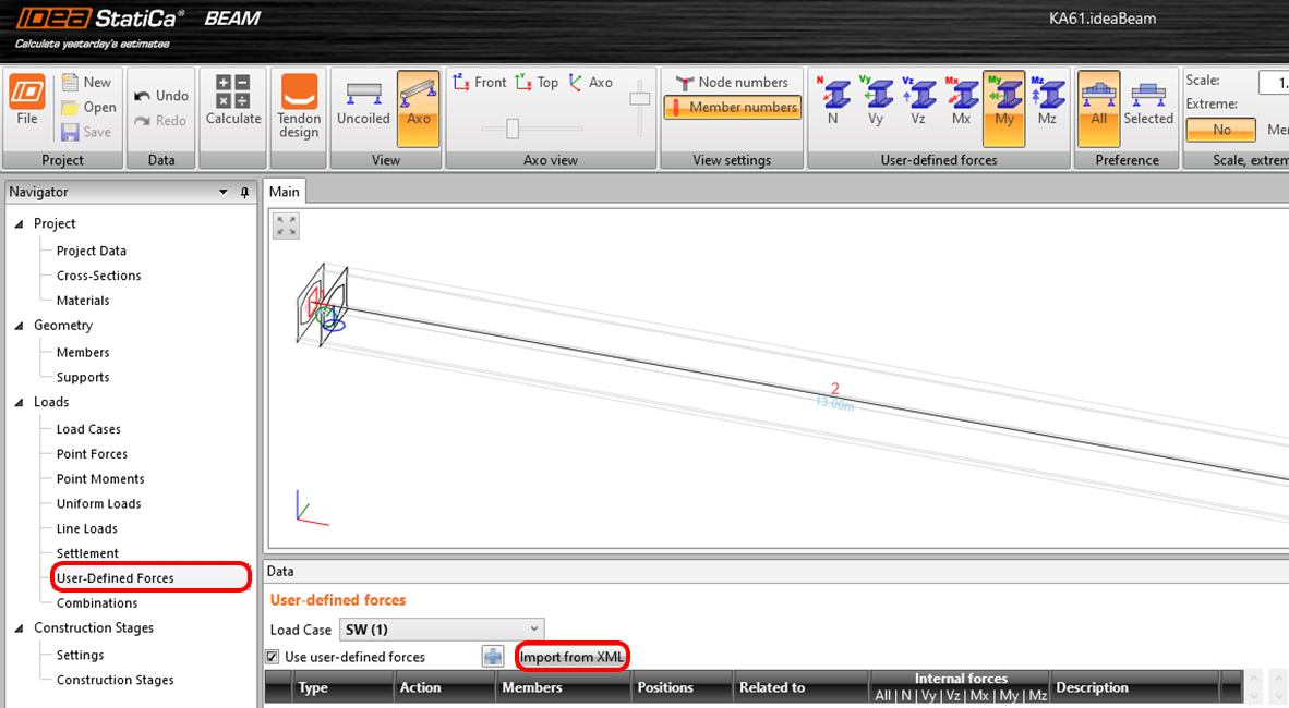
The model contains permanent load cases for one beam. User-Defined Forces will be used for the import of the remaining internal forces. In general, user-defined forces can be imported by copying from Excel or by using an XML file. Use the second approach and click on the Import from XML button.
The XML file selection dialog opens and searches for the EsaResults.xml file in the source data. This will bring up another dialog where you can set what is imported and how. The 3D model and its forces start from the beginning of the plate, which is slightly longer than your beam.
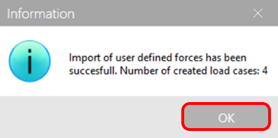
You are notified of a successful import by the following notification.
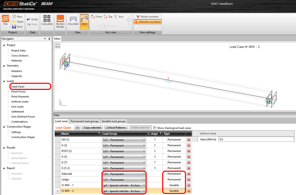
Four load cases were imported: Ledge, Sidewalk, Vr 4NV - 1 and Vr 4NV - 2. Switch to Load cases to set the Type and the Load Group. The load case type is toggled by clicking in the table column of the respective case.
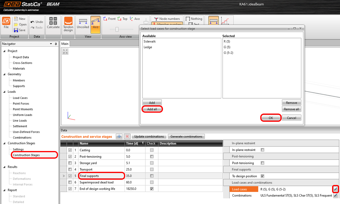
As can already be seen from the previous figure, the two imported cases are not assigned to the construction stages in which they appear. They thus would not be adequately accounted for in the TDA analysis. You can correct this by switching to the Construction Stages and adding the load cases to the Final Support stage. The Load Cases are added using the dialog in the following figure, where you add both permanent load states.
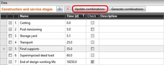
After assigning, click on Update Combinations to correctly sort the increments to all combinations in the model.
This action updates only the permanent load cases to all relevant combinations. Since you have also imported variable load cases, you must add them manually.
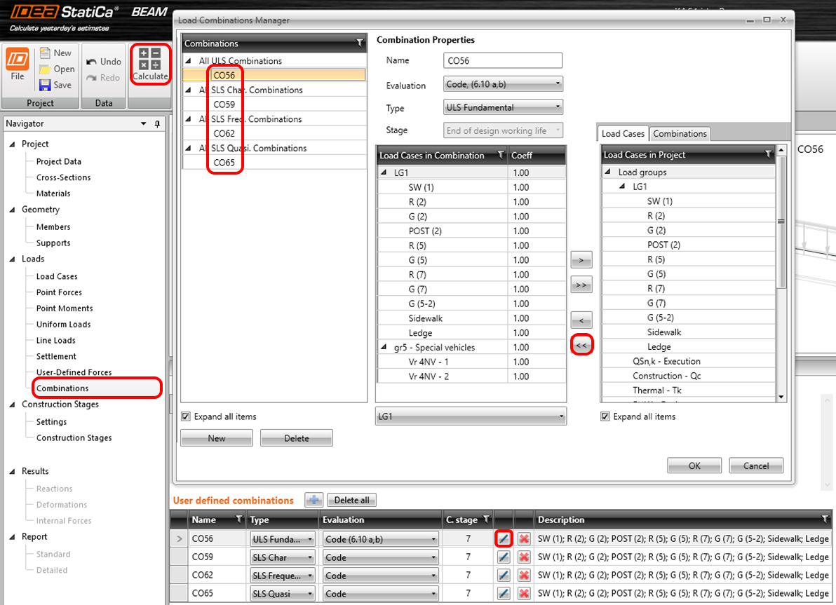
In this example, you will not do standard concrete checks but the iterative calculation of Bridge load rating, so only edit the user-defined combinations in the file using the pencil icon. Repeat the addition of all load cases to the combinations CO56, CO59, CO62 and CO65 using the arrow pair button as shown.
The last step on this tab is to run the TDA analysis using Calculate.
3 Calculation of Bridge load rating
Switch to the Data under the Bridge load rating to set the calculation. On the first tab, you set the checks which should be performed, the estimates of the multiplication factor if you want to speed up the calculation, and last but not least, the type of Bridge load rating, where you leave only Reserved.
On the second tab, set the positions for the Bridge load rating. Change the position of section 2 close to the support.
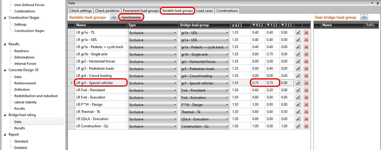
Switch the tab to Variable Load Groups and Synchronize variable load cases. Then set the partial coefficients according to the load capacity standard to 0.75.
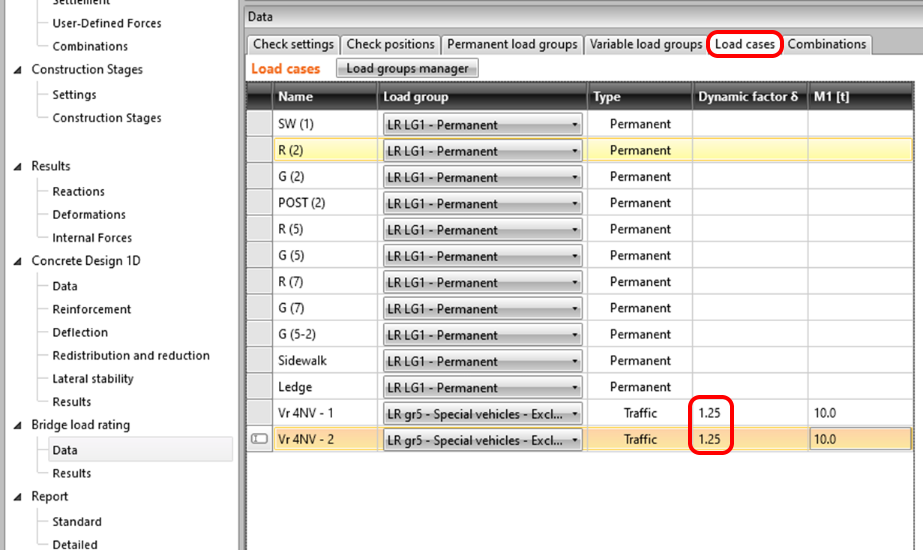
On the second-to-last settings page, named Load Cases, set the dynamic factor.
The Combinations tab is used to generate combinations for individual Bridge load rating types. After pressing the Generate button, only relevant combinations for the reserved load rating will appear due to the settings in the Data tab. The resulting list of combinations looks as follows:
5 Results
Switch to the Results tab to automatically start the iterative calculation. Once complete, you can view the resulting NT Reserved Bridge load rating on the right side of the screen.
6 Report
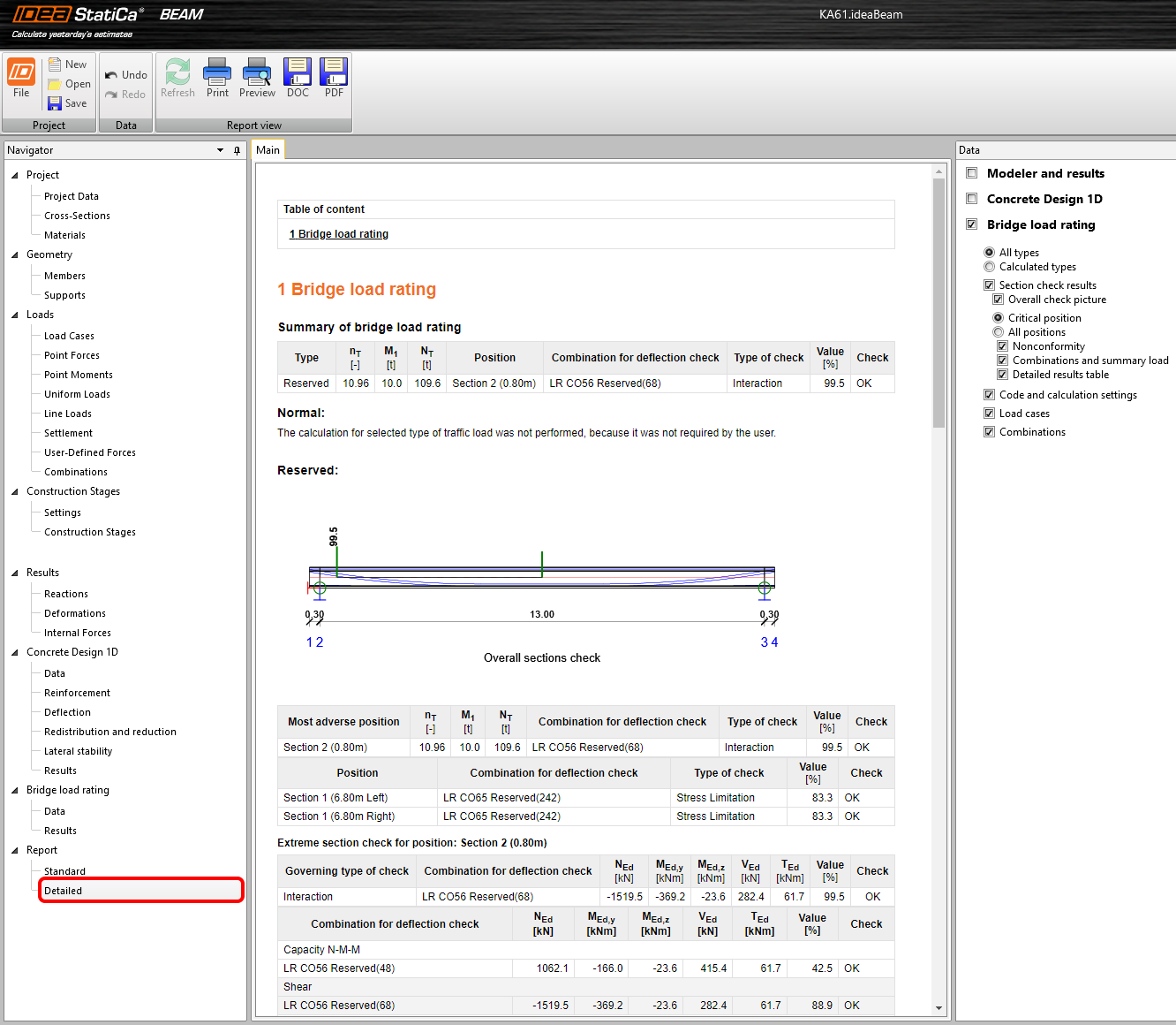
In the last step, switch to the Report section on the Detail tab. IDEA StatiCa offers a fully editable report that you can print or export.


