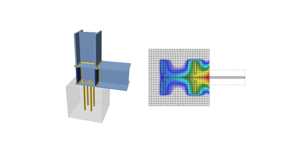
Code-check of concrete block according to Australian standards
Concrete below base plate is simulated by Winkler subsoil with uniform stiffness, which provides the contact stresses. The average stress at the loaded area in contact with base plate is used for compressive check.
Concrete bearing surface
Concrete bearing surface is checked according to AS3600: 2018 – Cl. 12.6. The design bearing stress at a concrete surface shall not exceed:
\[ ϕ f_b = ϕ 0.9 f'_c \sqrt{\frac{A_2}{A_1}} \le ϕ 1.8 f'_c \]
where:
- ϕ = 0.6 – capacity factor (Table 2.2) editable in Code setup
- f'c – characteristic compressive cylinder strength of concrete at 28 days
- A1 – bearing area
- A2 – largest area of the supporting surface that is geometrically similar and concentric with A1. The side slopes of the frustum are 1 longitudinally and 2 transversally with respect to the direction of the load.
The design bearing stress, σ, equals to the average stress under the base plate on the area below the base plate in contact with concrete.
Transfer of shear
The shear action at the base plate is assumed to be transferred from the column to the concrete foundation by:
- Friction between base plate and concrete / grout
- Shear lug
- Anchor bolts
Shear force transfer by friction
The shear capacity is calculated according to Gianluca Ranzi, Peter Kneen: Design of Pinned Column Base Plates, Journal of the Australian Steel Institute, vol. 36, no. 2, September 2002 – Chapter 6.5.3 as follows:
\[ ϕ V_f = ϕ μ N_c^* \]
where:
- ϕ = 0.8 – capacity factor
- μ = 0.55 – coefficient of friction editable in Code setup
- Nc* – column design axial compression load
Shear force transfer by shear lug
If shear force is transferred by the shear lug, the shear lug is modeled by finite elements, and its plates and welds are checked by the finite element method and weld components. Additional checks are required – bearing concrete strength; concrete edge strength.
\paragraph{Bearing concrete strength}
The bearing strength of concrete is checked according to Gianluca Ranzi, Peter Kneen: Design of Pinned Column Base Plates, Journal of the Australian Steel Institute, vol. 36, no. 2, September 2002 – Chapter 6.5.5:
\[ ϕ_c V_b = 0.85 ϕ_c f'_c A_{sl} \]
where:
- ϕc = 0.6 – capacity factor for concrete in bearing editable in Code setup
- f'c – characteristic compressive cylinder strength of concrete at 28 days
- Asl – projected area of the embedded shear lug in the direction of the force, excluding the portion of the lug in contact with the grout above the concrete member
Concrete edge strength
If a shear force is acting against a free concrete edge it should be verified that the concrete is able to carry the applied shear action. The concrete edge strength is checked according to Gianluca Ranzi, Peter Kneen: Design of Pinned Column Base Plates, Journal of the Australian Steel Institute, vol. 36, no. 2, September 2002 – Chapter 6.5.5:
\[ ϕ V_{ce} = ϕ 0.33 \sqrt{f'_c} A_{Vc} \]
where:
- ϕ =0.85 – capacity factor
- f'c – characteristic compressive cylinder strength of concrete at 28 days
- AVc – effective stress area defined by projecting a 45° plane from the bearing edges of the shear lug to the free surface in the direction of the shear load. The bearing area of the shear lug is excluded from the projected area
Shear force transfer by anchors
The shear force is assumed to be transferred by anchors. Force in each anchor is determined by finite element method. Each anchor or anchor group is checked for steel failure in shear, concrete edge failure, concrete pry-out failure, and combined tension and shear loading if tension is also present.


