
Design of Precast Concrete using User-defined Cross-section in IDEA StatiCa
Learn how to design and code-check this type of condition with a breeze in IDEA StatiCa using the RCS application.
In this tutorial, the end-user will learn through a step-by-step guide on how to design and code-check a user-defined reinforced concrete cross-sections according to Eurocode.
1. Creating a new project
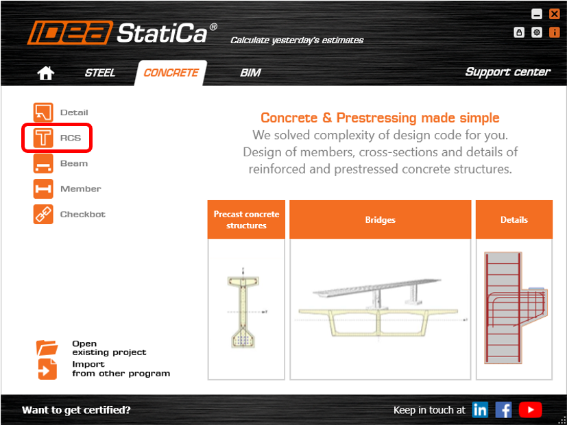
Open IDEA StatiCa and click on CONCRETE tab and select the application RCS.
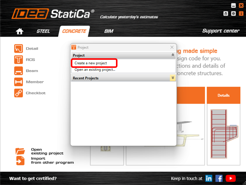
-In the Project window, click on CREATE NEW PROJECT.
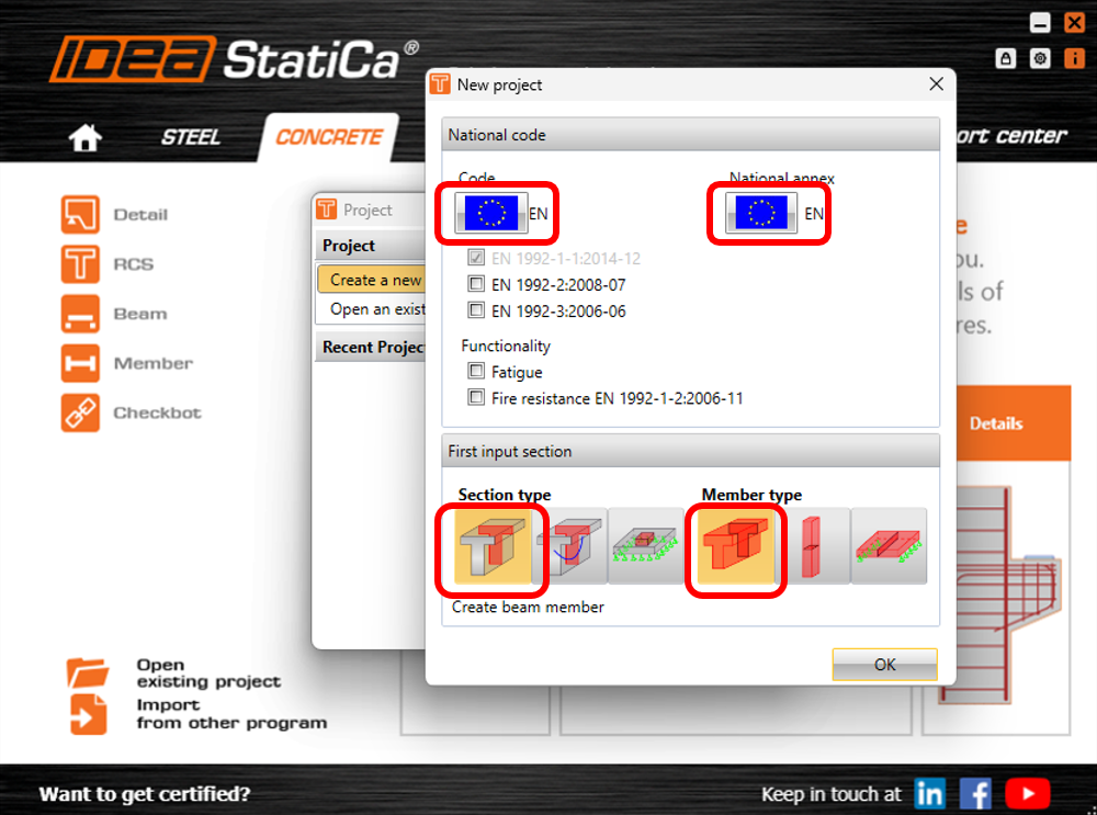
Next, you need to select the code and the national annex. In this example, we will leave the default settings to Eurocode. Select 1D REINFORCED SECTION under section type and select BEAM under member type.
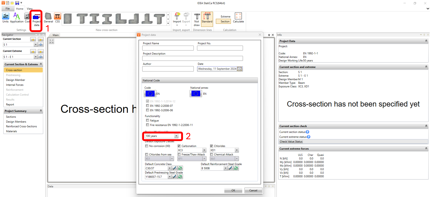
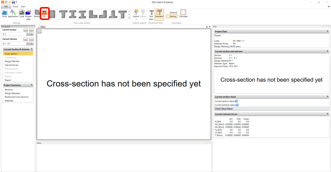
In the Cross Section Navigator window, click on Project Data icon. In Project Data window, change the design working life to 100 years and click on OK.
2. Modelling and Reinforcement
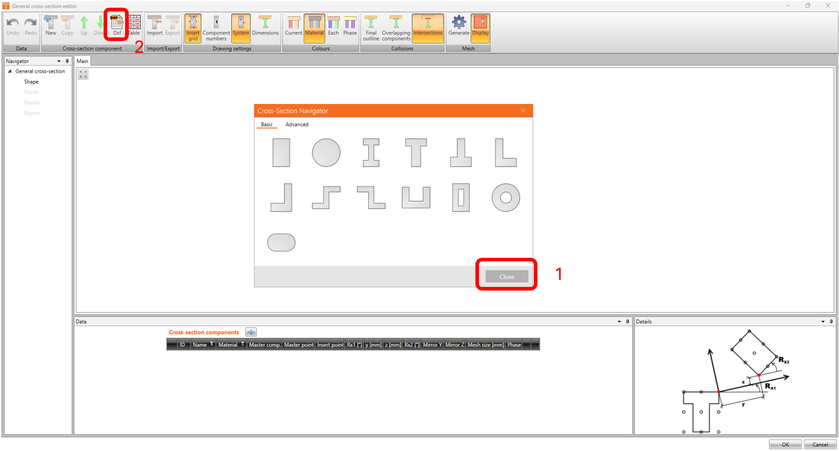
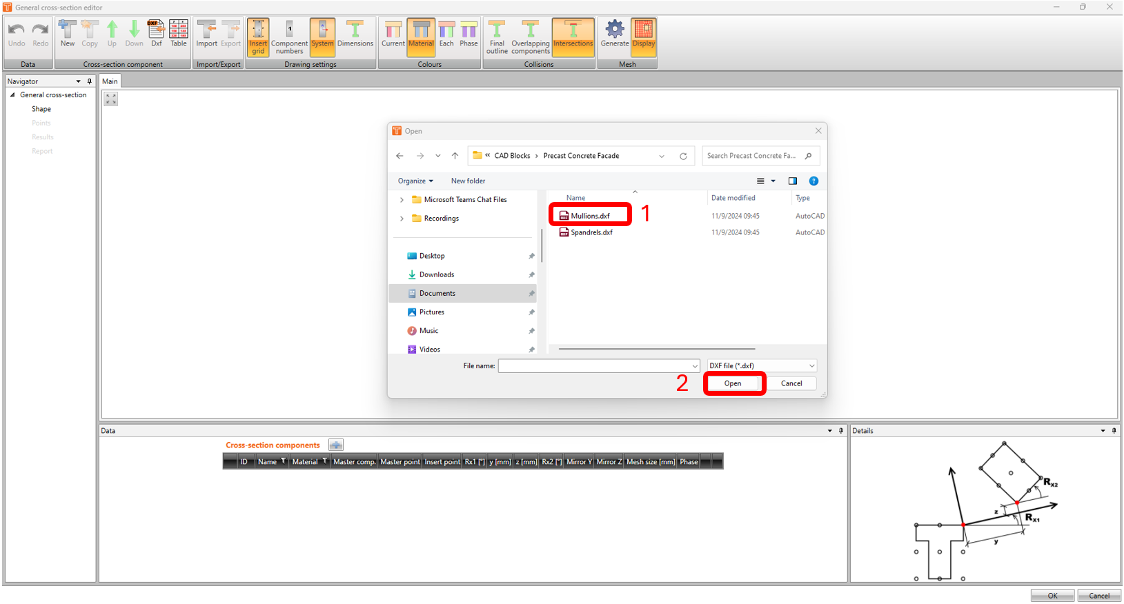
Click on IDEA CSS icon. The General Cross Section window will appear. Close the Cross Section navigator and click on DXF icon and open up "mullions.dxf" (file can be downloaded at the end of this article).
In the General cross-section elements from dxf window, choose the correct units in millimeters. Click on the shape of the precast element. Under insertion point, select CENTER OF GRAVITY in the dropdown list. Select OUTLINE before hitting OK.
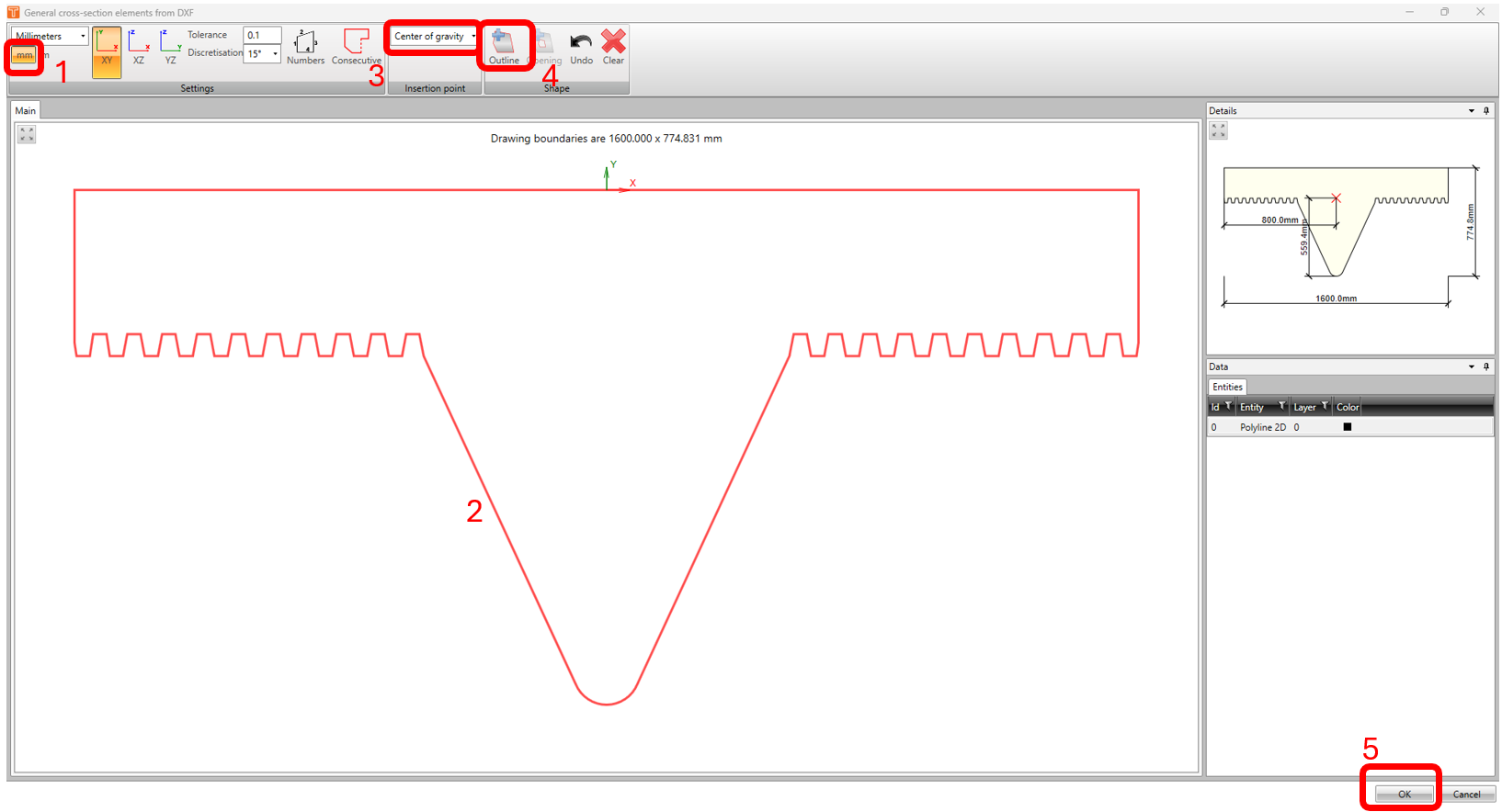
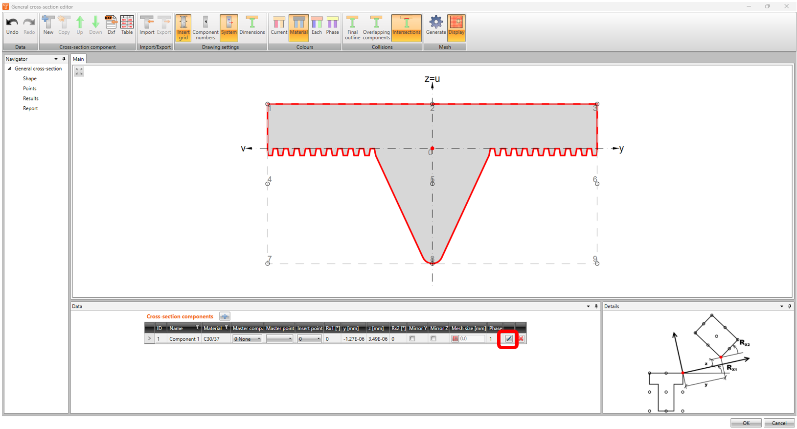
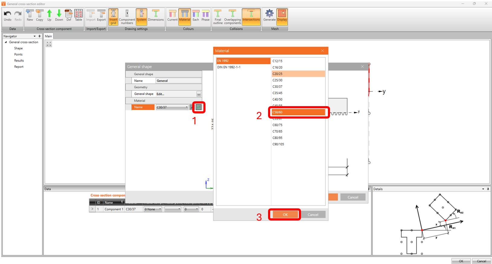
-The shape of the cross-section is now imported into the General cross-section editor. Now, we have to change the concrete material by clicking on the EDIT button under cross-section components.
-Change the material from C30/37 to C50/60
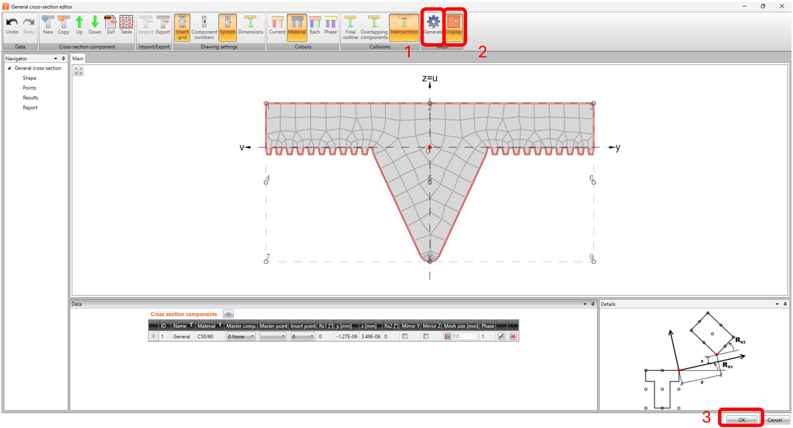
To generate mesh, click on GENERATE and DISPLAY icon.
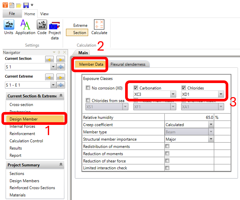
In the Design Member Navigator window, click on MEMBER DATA tab and check CARBONATION and CHLORIDES. Use the default values XC3 and XD1.
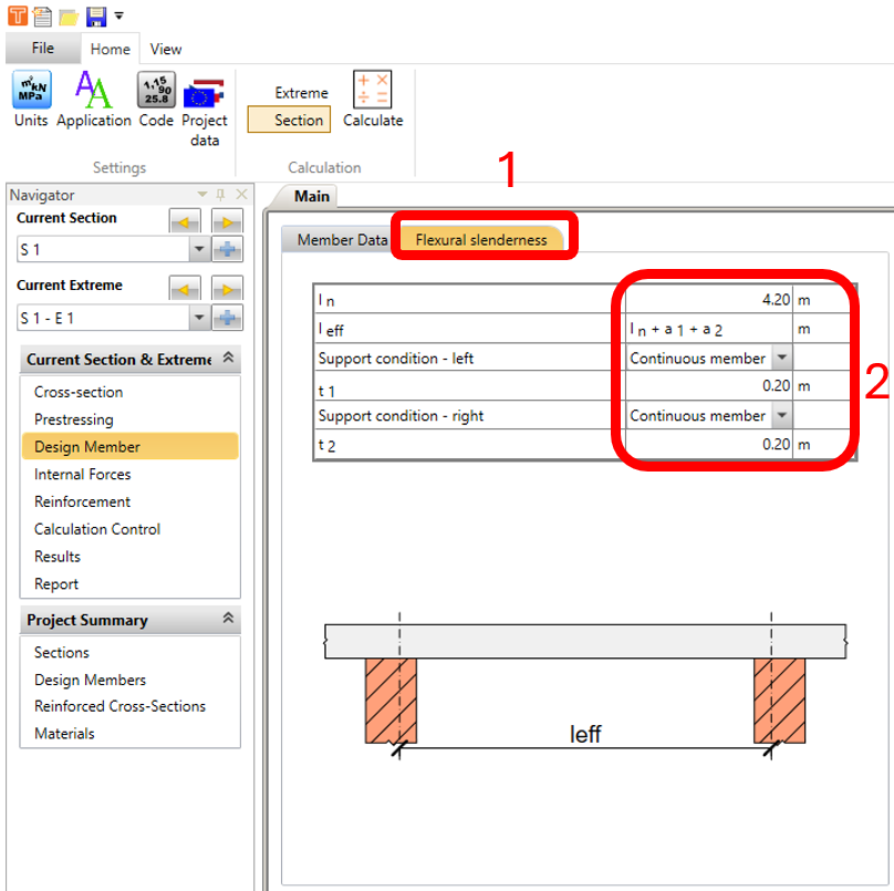
In the FLEXURAL SLENDERNESS tab, change the values as below.
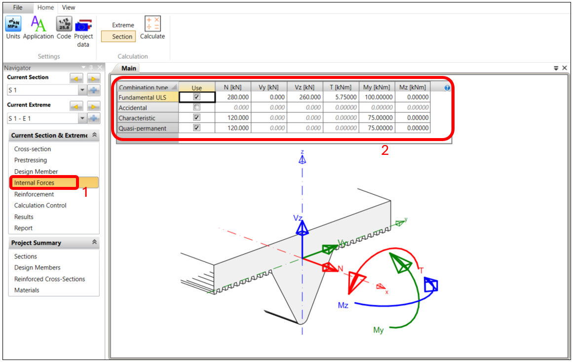
In the Internal Forces Navigator window, apply the values of the internal forces as below (These values should come from your global analytical FEA model). Note that in this example, the applied axial force (N) is in tension as the structure is hanging with other elements attached to it.
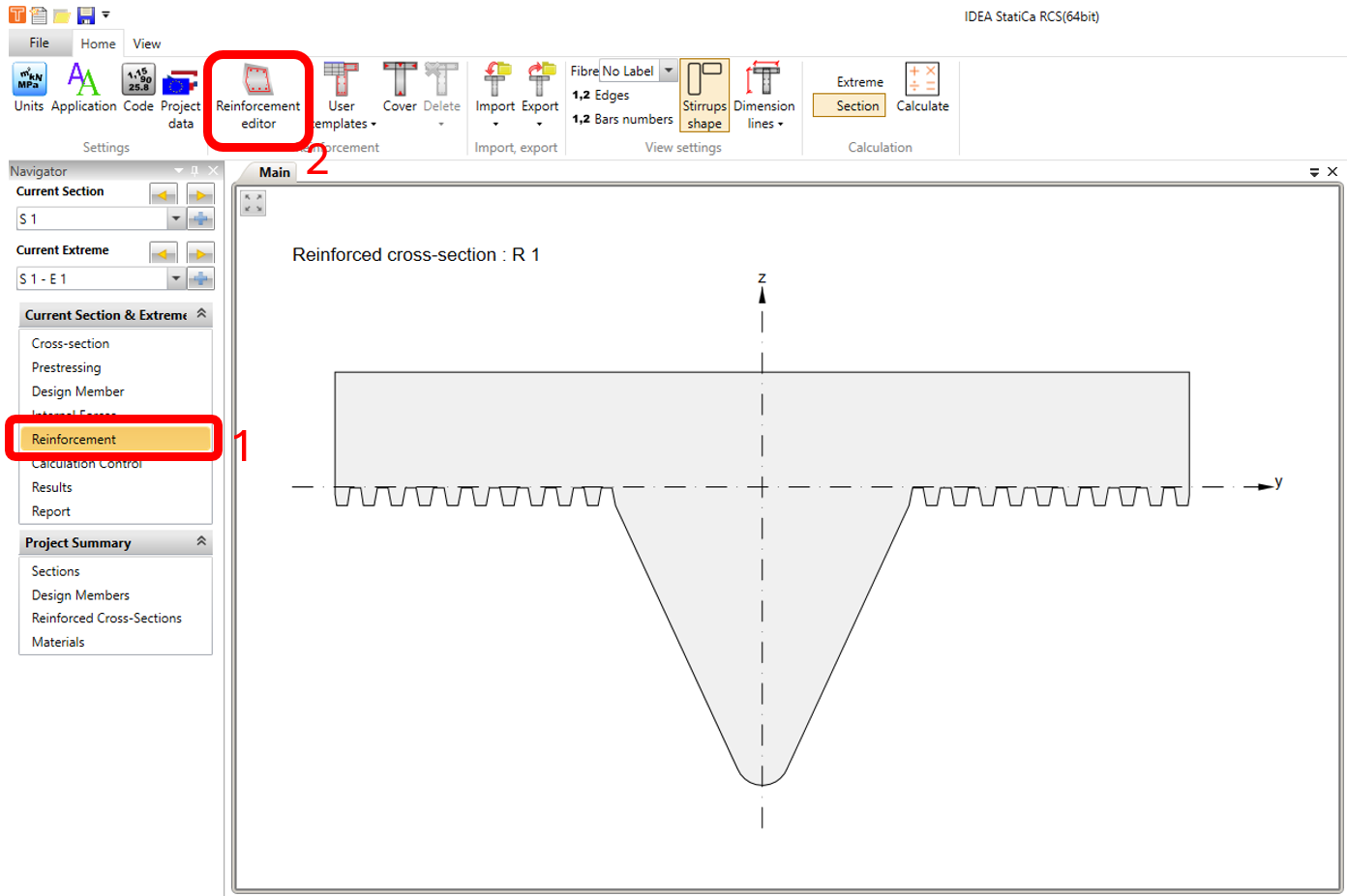
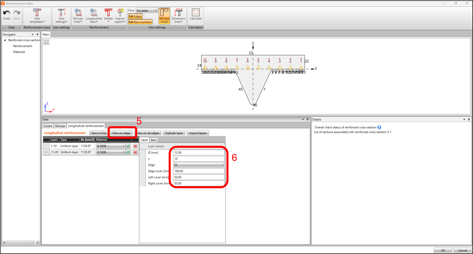
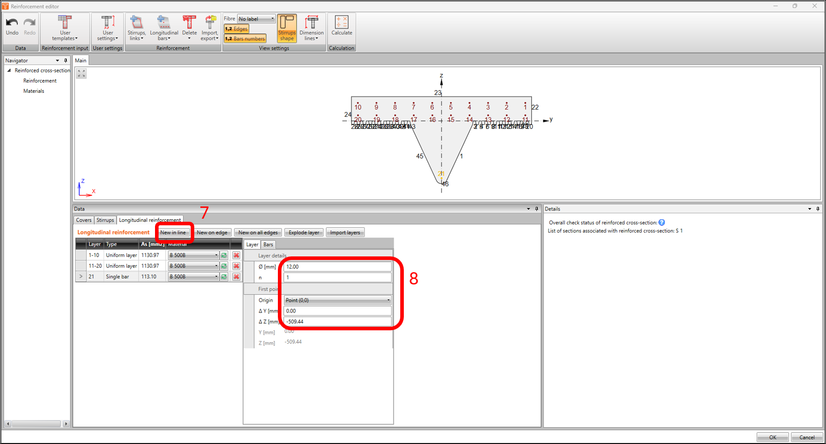
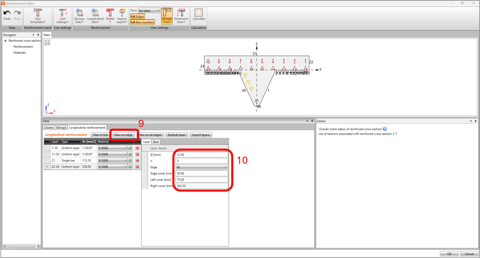
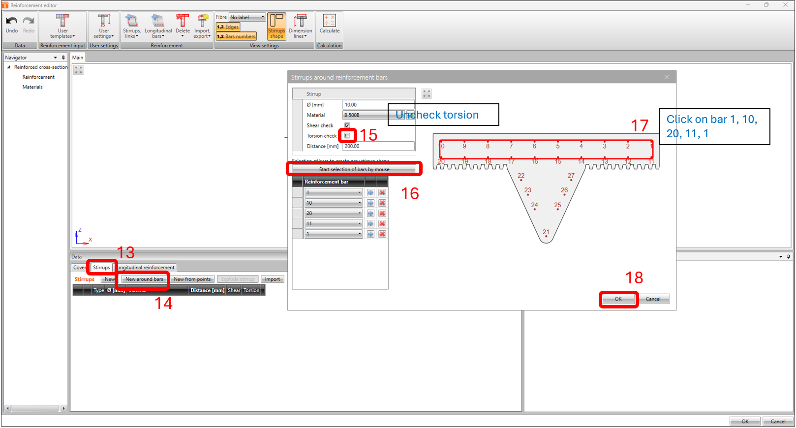
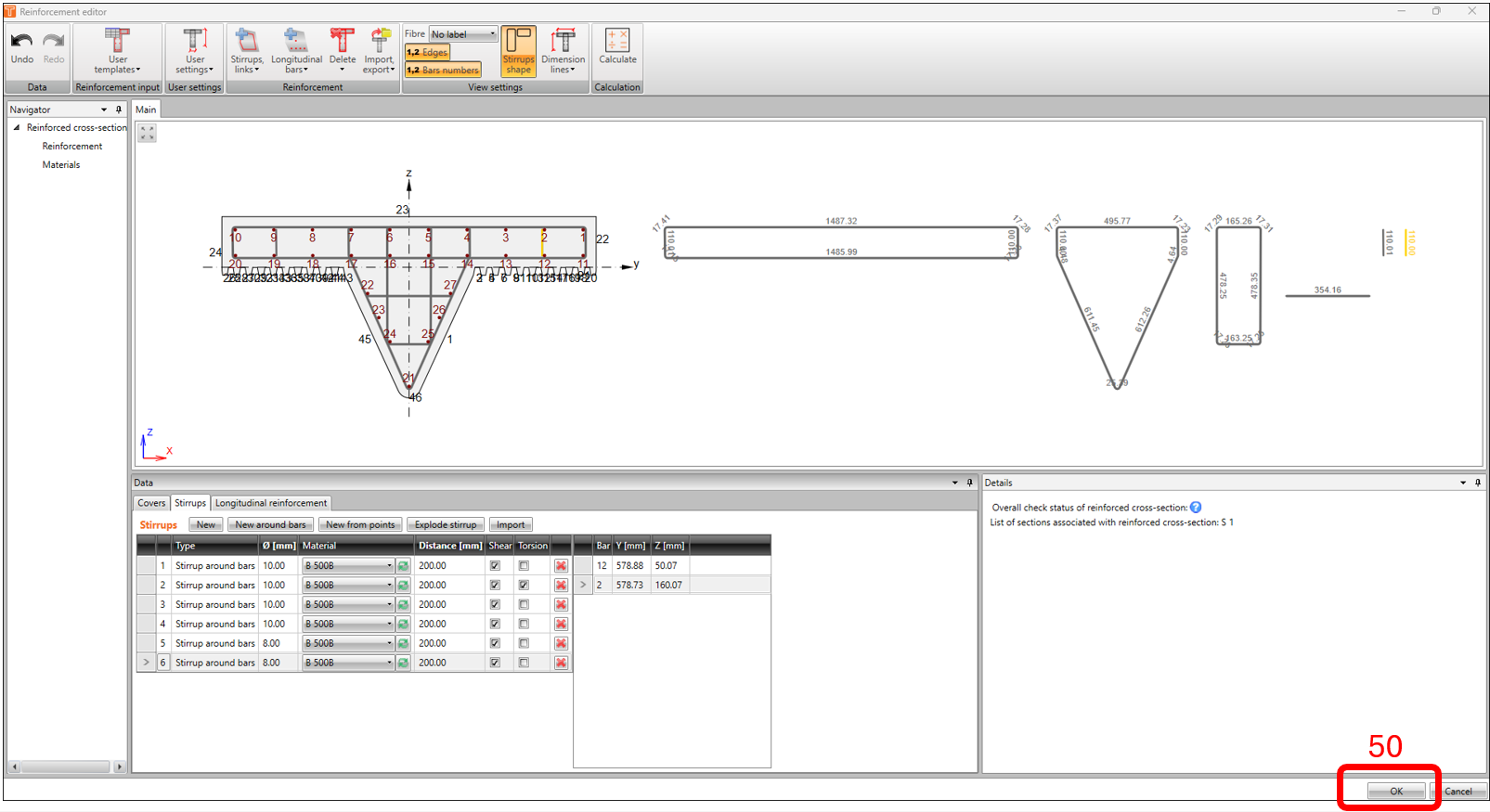
In the Reinforcement Navigator window, click on REINFORCEMENT EDITOR icon.
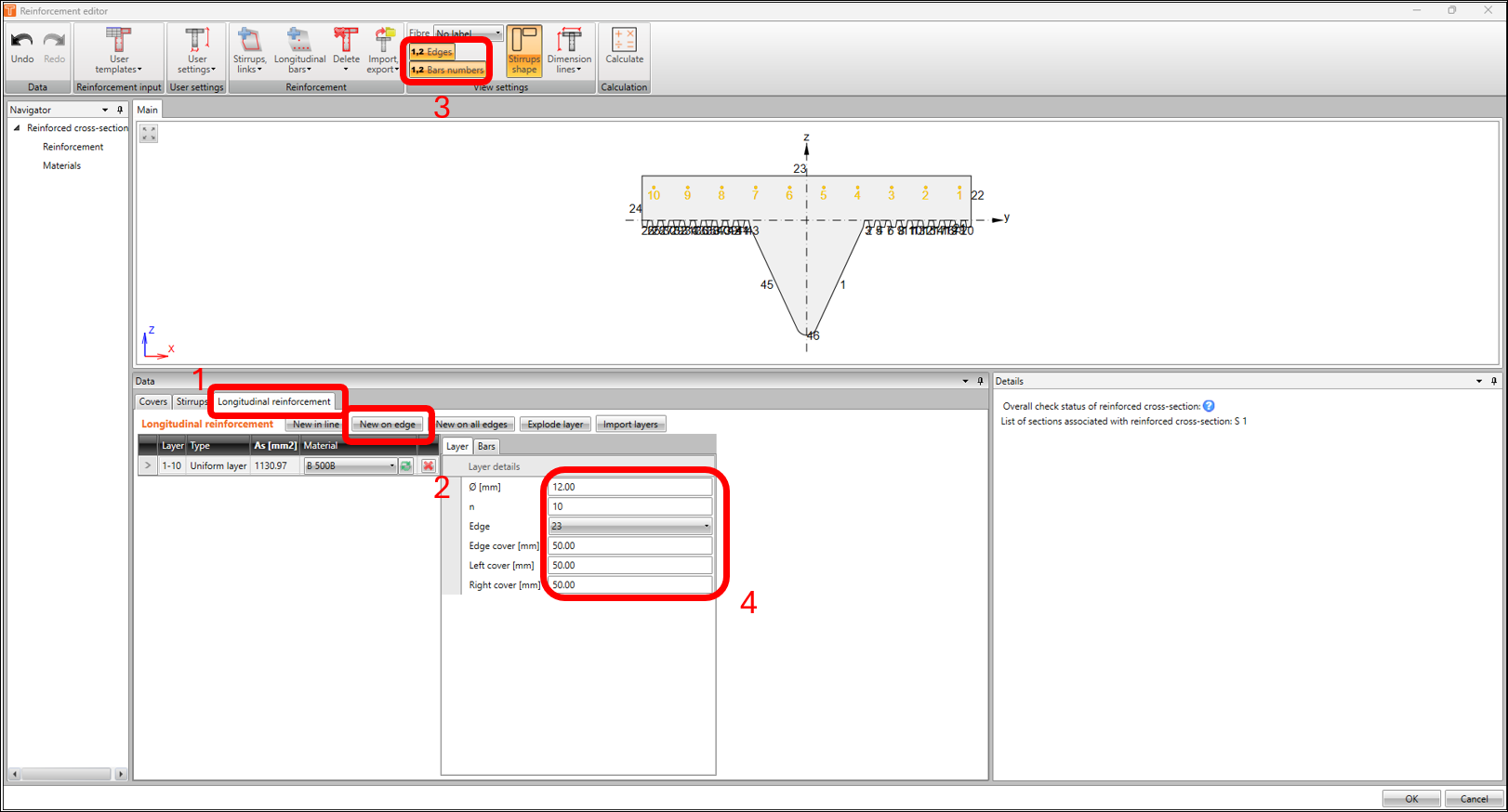
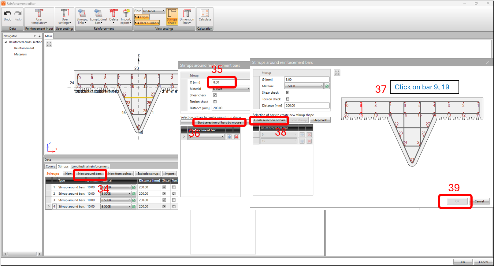
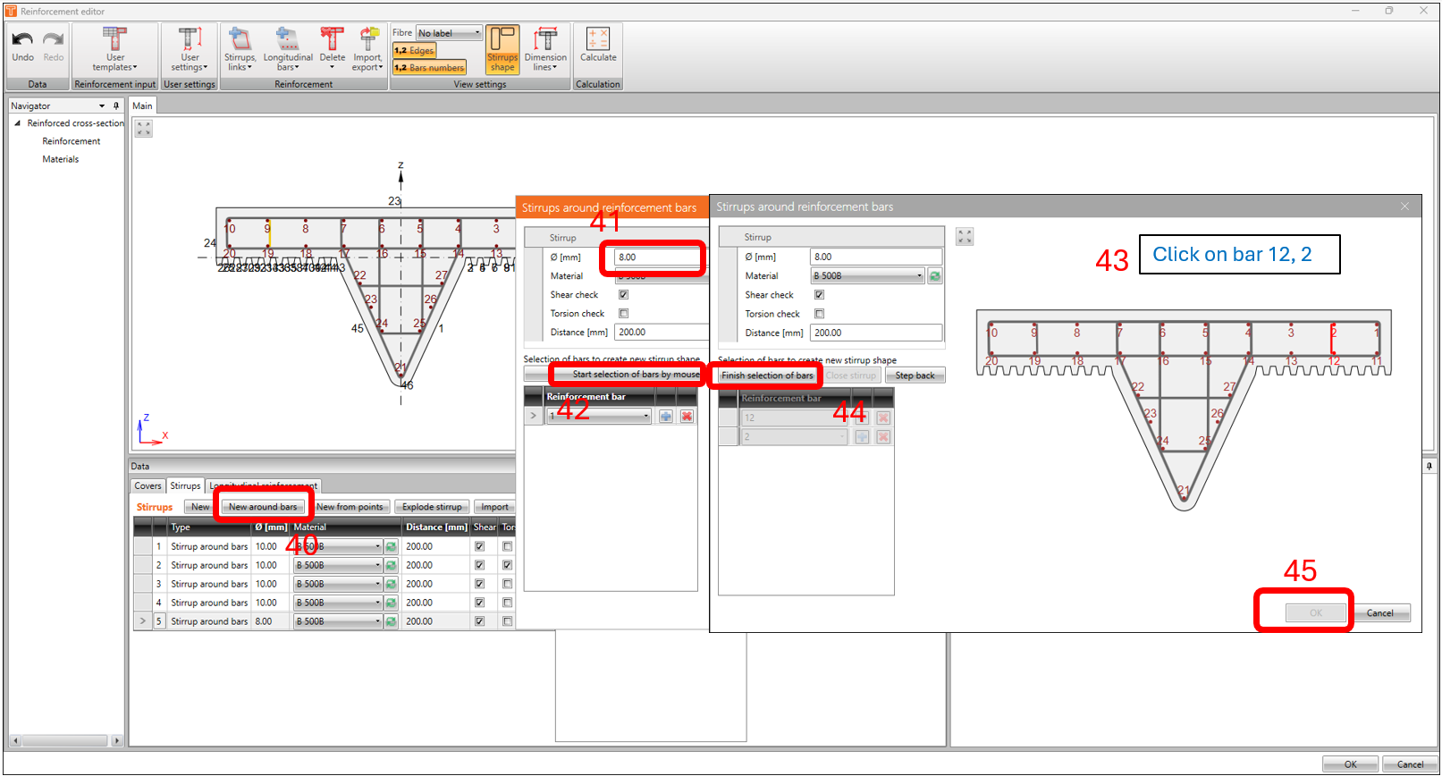
Usually, the best option would be to use a template or import a reinforcement file (which is available for download at the end of this article), but in this example, we’ll do the basics and use the steps highlighted and using the same parameters in the following images below.
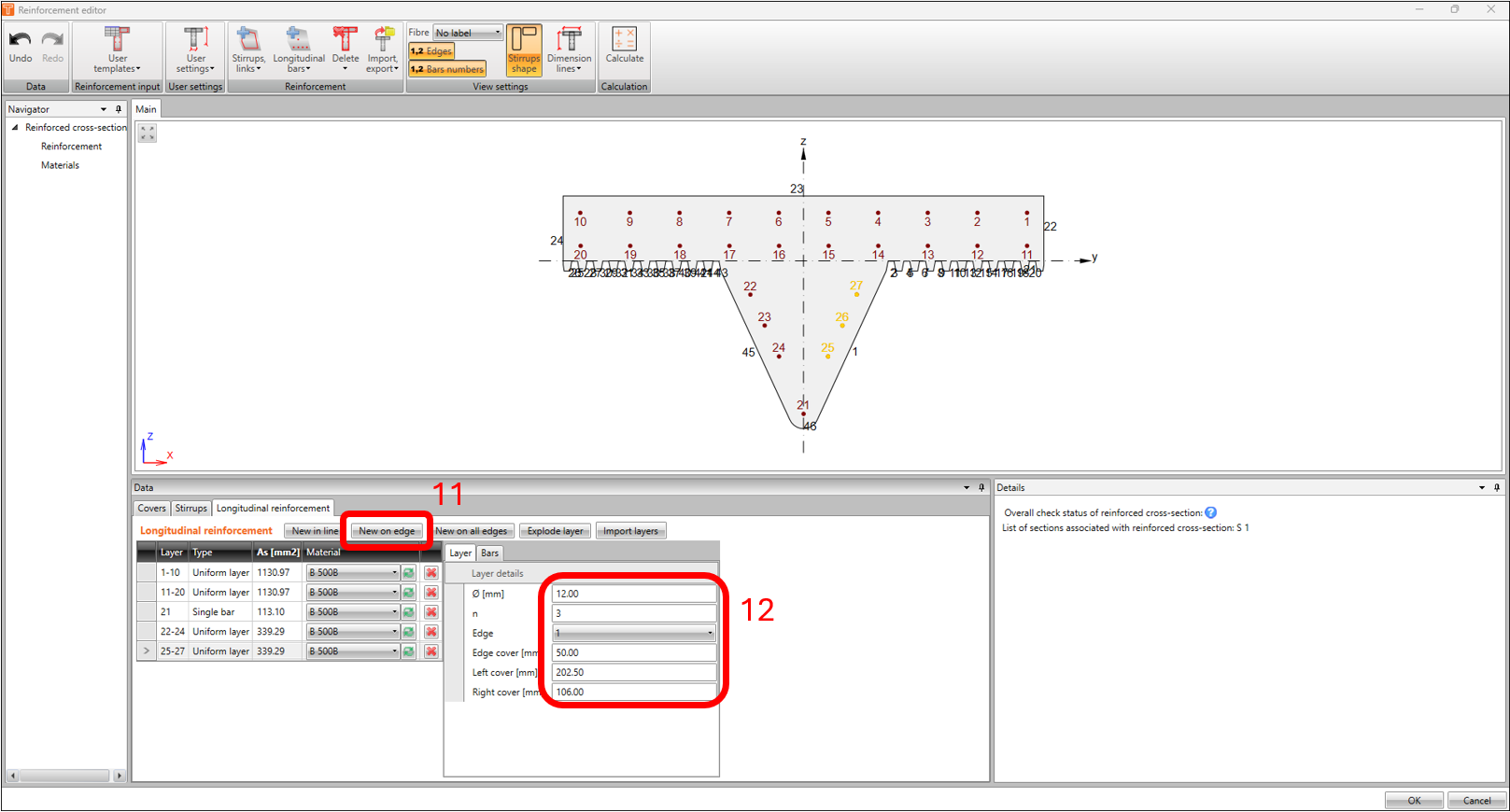
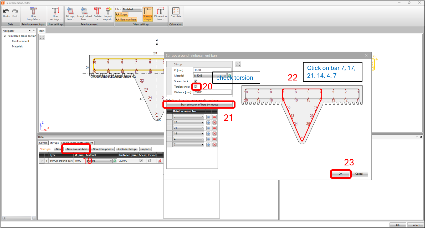
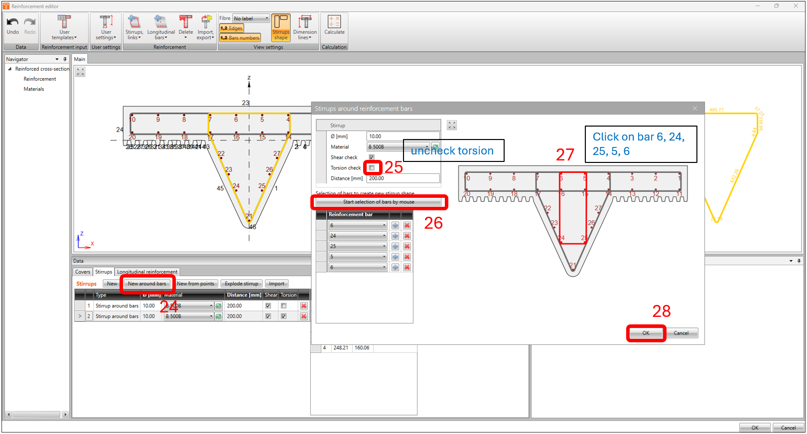
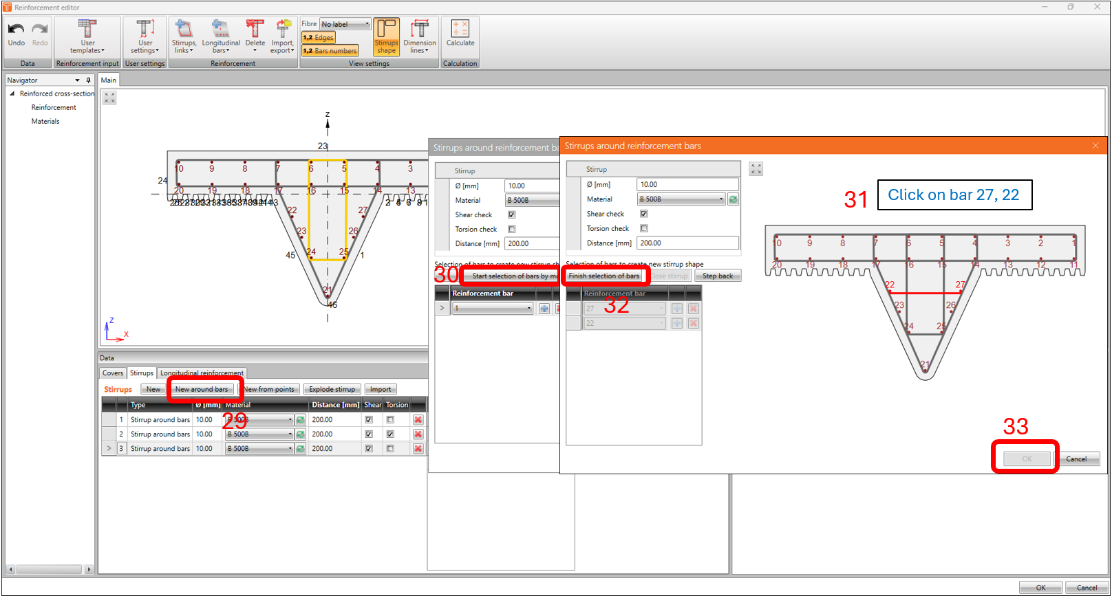
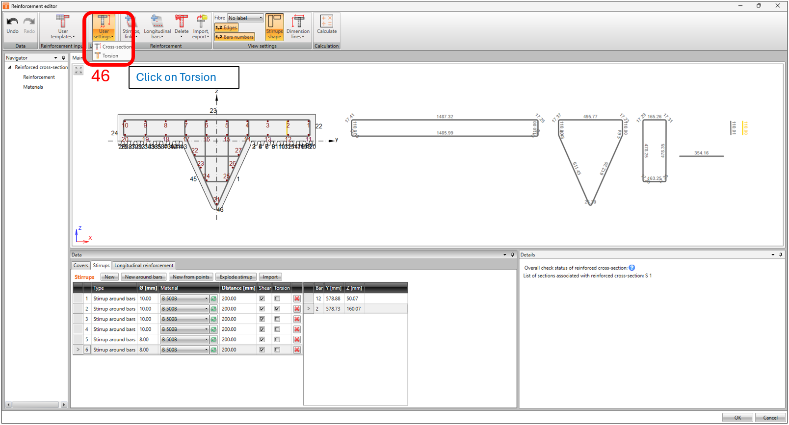
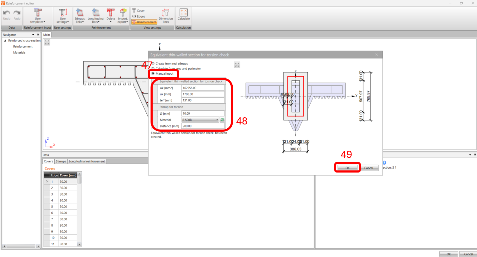
As we have an irregular shaped cross-section, we need to manually specify the equivalent thin-walled section according to EN1992-1-1 clause 6.3.2 for torsional check. This is also briefly described in this article How to set effective thin-walled section for torsion check.
3. Design and Code-check
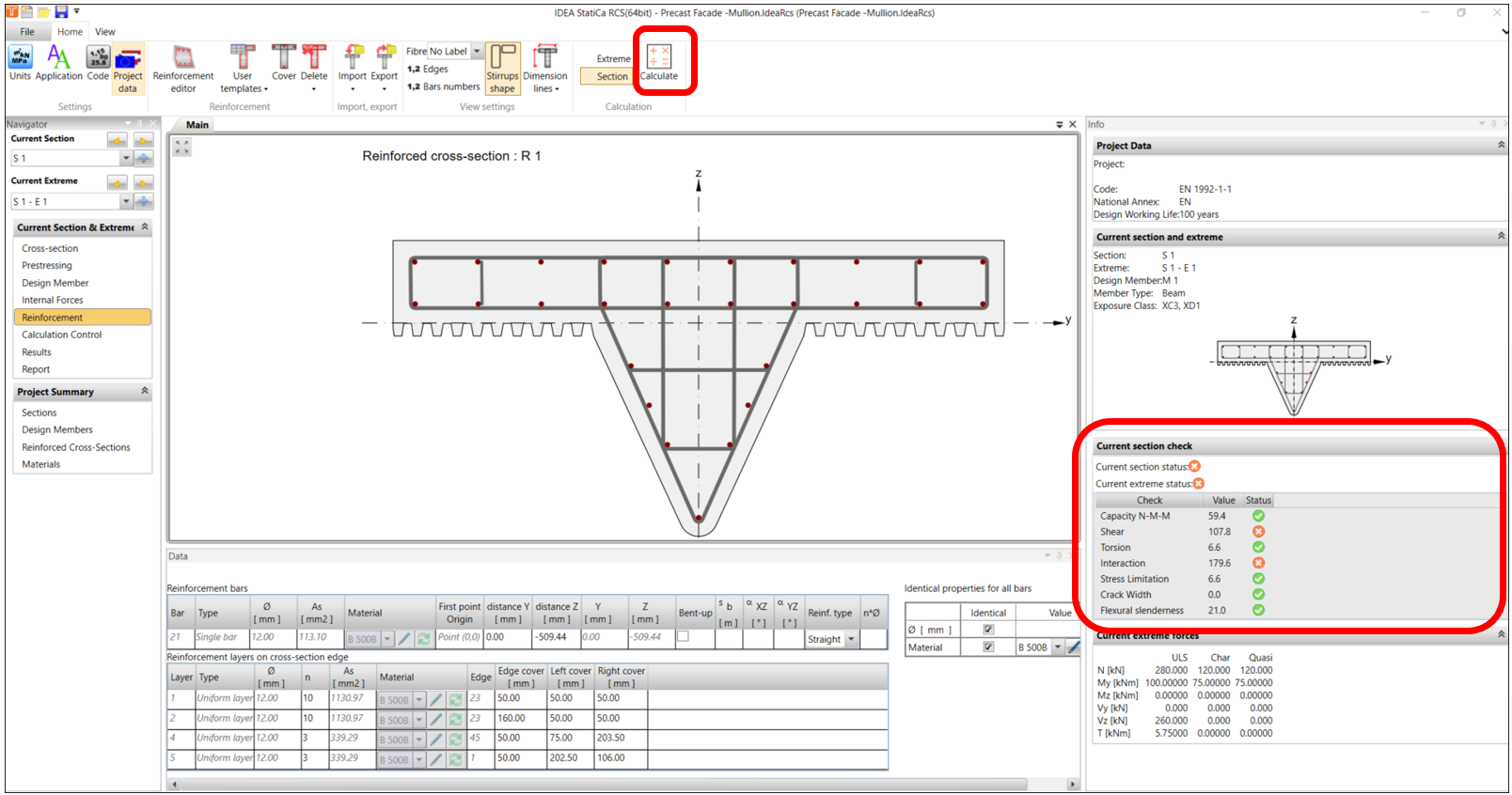
Now that we’re done with modelling the reinforcement, we’re now ready to run the calculation. Back in the reinforcement Navigator window, click on CALCULATE. In this example, the result of the calculation returns an invalid status in the verification for shear and interactions.
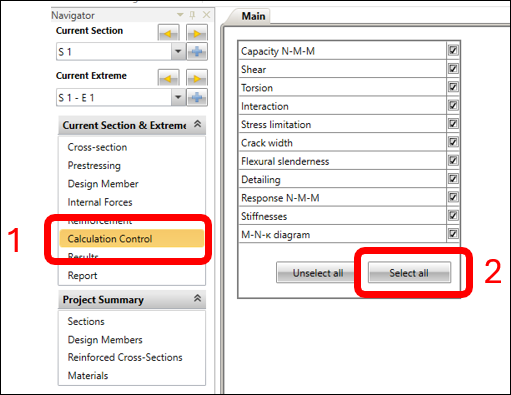
To show all performed verifications, in the CALCULATION CONTROL Navigator Window under the MAIN tab, click on SELECT ALL.
Now let’s go to the RESULTS navigator window and examine the results of the ULS and SLS checks. We need to resolve the shear checks in the SHEAR tab.
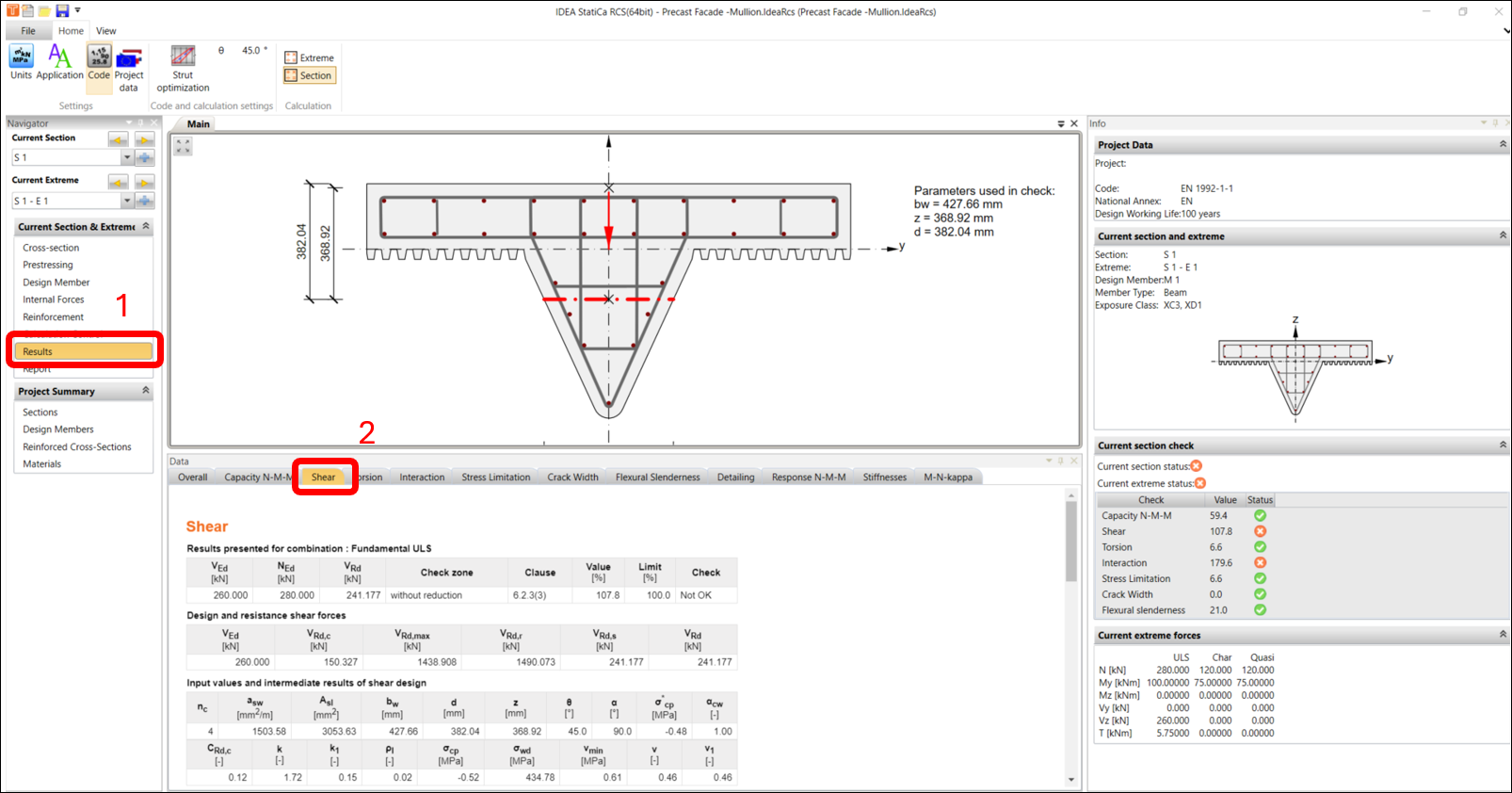
To improve the performance of the shear checks, you have the possibility to change the angle of the compression strut according to EN 1992-1-1 6.2.3 in the code and calculation settings. In this example, we’ll change the value from 45 change to 40 degrees.
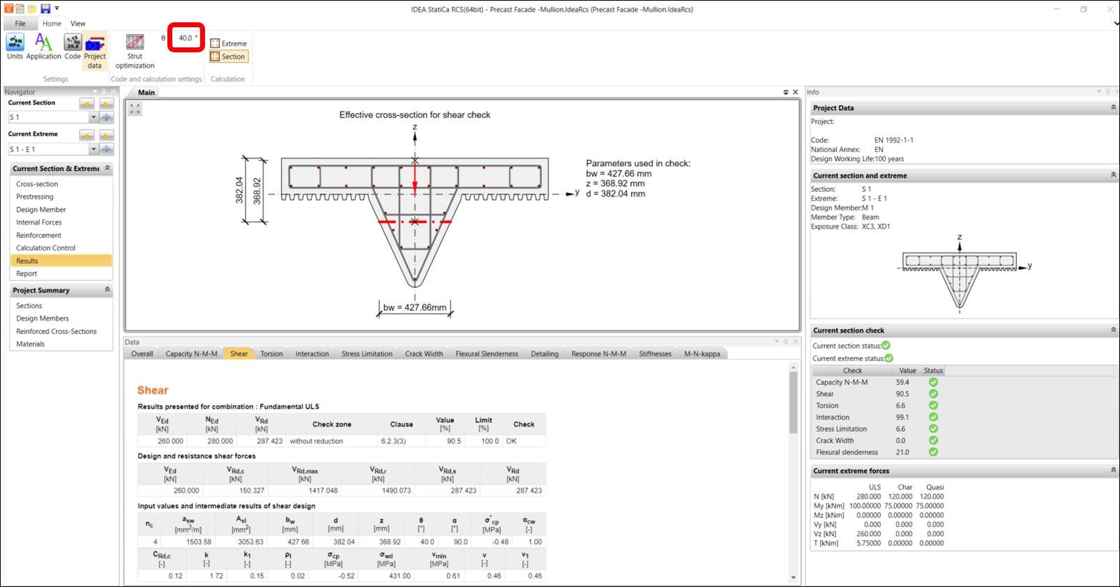
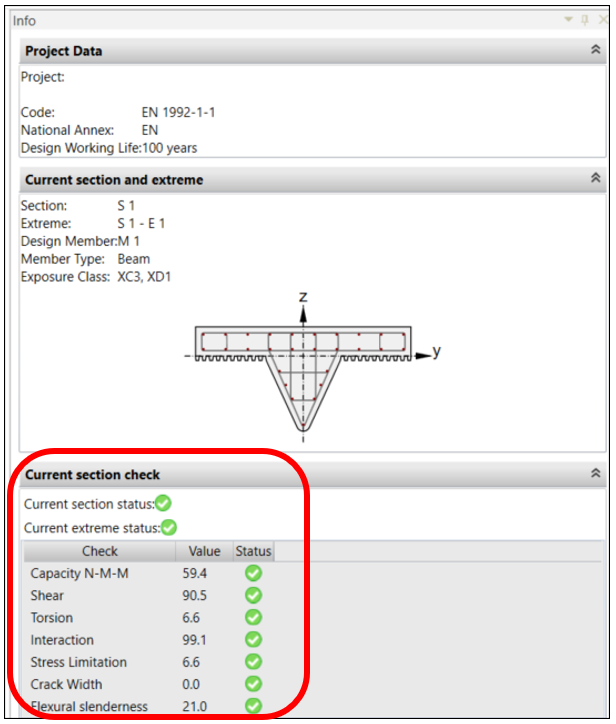
And the checks are now OK. You may go through by switching different tabs. You may find that there is nonconformity under INTERACTION tab according to EN1992-1-1 clause 6.3.2(5). As we are providing shear reinforcement, this notification of nonconformity is OK. VRd,c in the interaction equation refers to section without reinforcement.
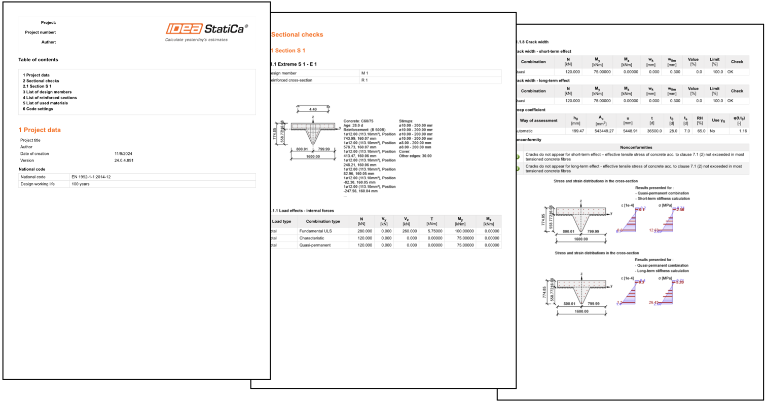
4. Calculation Report
You are now ready to print or save a copy of the calculation report. IDEA StatiCa offers a fully customizable report that can be printed and saved in an editable format.
Descargas archivos adjuntos
- Mullions.dxf (DXF, 123 kB)
- Precast Facade - Mullion_Reinforcement.nav (NAV, 2 kB)
- Precast Facade - Mullion.IdeaRcs (IDEARCS, 169 kB)