The N-M-κ diagram shows an element's curvature (bending stiffness) as a function of an applied bending moment and normal force. There are three types of N-M-κ diagrams:
- short-term,
- long-term
- ULS.
These diagrams differ in the types of stress-strain diagrams used for the calculation (explained below).
The stiffness calculation for selected characteristic states of the cross-section is used to determine the N-M-κ diagram. In general, it can be any cross-sectional state from which the response is calculated and from which the bending stiffness and curvature are derived. In IDEA RCS, we consider four characteristic points (Mr, Mc, Ms and Mu)
Mr - the cracking moment
The cross-section is subjected to user-defined normal force and the plane of strain starts to rotate (in the direction of the specified bending moment) until the ultimate tensile strength of the concrete is reached in a concrete fibre (for concrete grade C30/37 this is fctm = 2,896 MPa). A bilinear stress-strain diagram with a horizontal plastic branch for both reinforcement and concrete is used for the calculation.
Mc - the bending moment when the compressive strength of the concrete is reached
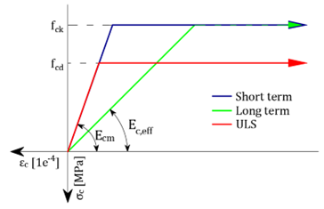
From the previous step, the most utilized concrete fibre in compression is identified. For this fibre, the strain at the ultimate strength of concrete (fck/Ecm for short-term, fck/Eceff for long-term and fcd/Ecm for the ULS diagram) is set. Based on the defined normal force and the direction of bending moment, the iteration process to find the plane of strain is run to find an equilibrium between the response of the cross-section and the defined normal force. A bilinear stress-strain diagram with a horizontal plastic branch for both reinforcement and concrete is used for the calculation.
Ms - the bending moment when the yield strength in the most utilized reinforcement bar is reached
Another characteristic point of the N-M-κ diagram is the stress-state of the cross-section when the yield strength in the most utilized reinforcement bar is reached (rebar strain is equal to fyk/Es for the short- and long-term diagrams, fyd/Es for the ULS diagram). The iteration process finds an equilibrium of normal forces in the cross-section by rotating the plane of strain around the point specified by the position of the most utilized reinforcement bar. A bilinear stress-strain diagram with a horizontal plastic branch for both reinforcement and concrete is used for the calculation.
Mu - the bending moment at the ultimate limit state
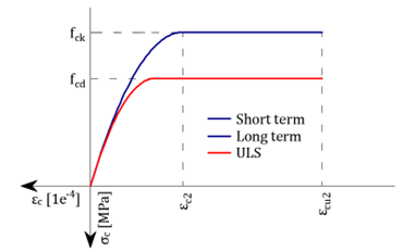
This is the ultimate load bearing capacity of a cross-section in bending, when the cross-section is subjected to defined design normal force Ned. For the calculation of the cross-sectional capacity it is assumed that the compressive strength in the most utilized fibre of concrete and the tensile strength in most utilized reinforcement bar are reached (maximum strain for concrete εcu = 0,1 and for reinforcement εs,max = 0,5. A bilinear stress-strain diagram with a horizontal plastic branch for the reinforcement and a parabola-rectangular diagram for the concrete are used for the calculation.
The resulting stiffness and curvature due to the user-defined combination of normal force and bending moment ( Md) are then calculated using linear interpolation of the individual characteristic points of the N-M-κ diagram.
Calculation of stiffnesses and curvatures
The stiffnesses and curvatures for each cross-sectional stress state (Mr, Mc, Ms or Mu)are calculated directly from the rotation of the plane of strain.
\[E{{A}_{x}}=\frac{N}{{{\varepsilon }_{x}}}\]
EAx . . axial stiffness of the element
N . . . . the specified normal force
εx . . . axial strain at the centre of gravity of the concrete cross-section
\[E{{I}_{y}}=\frac{M}{\kappa }\]
EIy . . . bending stiffness of the element
M . . . the calculated bending moment Mr, Mc, Ms or Mu
κ . . . . the curvature of the element, calculated as the tangent of the angle between the plane of the strain and the longitudinal element axis
Practical example
A concrete cross-section (concrete grade C30/37) is reinforced with ϕ32 reinforcement (grade B500B). The defined quasi-permanent combination is N = -730 kN and My = 557 kNm.
The plane of strain for the characteristic point Ms is determined by IDEA RCS as follows:
\[E{{A}_{x}}=\frac{N}{{{\varepsilon }_{x}}}=\frac{730}{6,9471\cdot {{10}^{-4}}}=1050,798MN\]
\[\kappa =\frac{28,4386\cdot {{10}^{-4}}}{0,463}=61,422\cdot {{10}^{-4}}{{m}^{-1}}\]
\[E{{I}_{y}}=\frac{{{M}_{s}}}{\kappa }=\frac{2277,4}{61,422\cdot {{10}^{-4}}}=370,776MN{{m}^{2}}\]
Stress-strain diagrams used for the calculation
Reinforcement - Mr, Mc, Ms and Mu
Concrete - Mr, Mc, Ms
Concrete - Mu


