Release notes IDEA StatiCa Steel 20
Introduction
The new version of IDEA StatiCa is here! It is the biggest implementation of customer feedback and wishes we have had in years. And that means something – IDEA StatiCa is used by over 3500 customers who share more than 4000 unique IDEA StatiCa projects every month.
How did we get from number 10 to 20? The sheer volume of new functionalities seems to justify the “+10,” but the reason is more straightforward – align the numbering with year count. In 2020, we release IDEA StatiCa 20.
This version brings an exceptional volume of new features and improvements. All that with our focus to enable engineers to work faster, evaluate the requirements of the national code thoroughly, and use the optimal amount of material. Highlights are:
- New online licensing system – no more hassle with installation
- IDEA StatiCa can now generate “sketches” to speed up the detailing process
- 110 new connection templates added to the starting wizard
- Steel-to-timber connections can now be designed and checked
- Cross-section databases are now automatically filtered based on your regional settings
- Hong Kong and Indian codes are now supported
We hope you will enjoy all our new features and improvements and would love to hear your feedback anytime.
BTW, expect a little break from new features in Steel for the rest of the year. The 2020 autumn release will be focused on Concrete and BIM.
Calculate yesterday’s estimates!
New licensing system
The new online licensing system of IDEA StatiCa was implemented. It is account-based, which means that all you need to start IDEA StatiCa 20 is to insert your username (by default, an email) and password.
Why?
- Our customers struggled with logistics related to license codes, license files, and dongles.
- IDEA StatiCa license could be fixed without the cooperation of the end-user (reactivation, etc.).
- Our customers had to deploy the network license on their servers.
- Company license could not be easily shared with employees on the road or on home-office
The new online licensing system of IDEA StatiCa solves all these issues and much more. Everything is provided in a robust and secure IDEA StatiCa cloud for which users need only one thing to access – their username (by default, an email) and password.
How does the online license work?
- IDEA StatiCa installation regularly checks with IDEA StatiCa license server to update the license and verify product configuration.
- IDEA StatiCa users do not have to be online all the time. The license will work for 72 hours without an internet connection. After that, connecting to the licensing server is necessary.
- Admins, as well as end-users, can view/edit the license via IDEA StatiCa Customer portal, an online backend with their licensing data
How to setup IDEA StatiCa version 20
- Every customer of IDEA StatiCa has a primary email address in our system (confirmed in a past order)
- With the release of version 20, IDEA StatiCa will send Admin credentials to this email. The license will have entitlements based on purchased products and seats.
- Admins can then add and remove other users in the organization
- Every user in the organization can consume only selected type of IDEA StatiCa products
IDEA StatiCa license manager
Migration disclaimer
- IDEA StatiCa 20 has only one way to license and launch – the new online licensing system.
- The old licensing systems (Eleckey, HASP) of versions up to 10.1 remains unchanged and functional. Lifetime entitlements (now called "Perpetual") will work indefinitely, but their technical support will be terminated on 30. 6. 2021. After this date, license resets, reactivations, and other licensing support will not be provided anymore. Kindly make sure that your organization migrates to version 20 as soon as possible.
IDEA StatiCa Connection
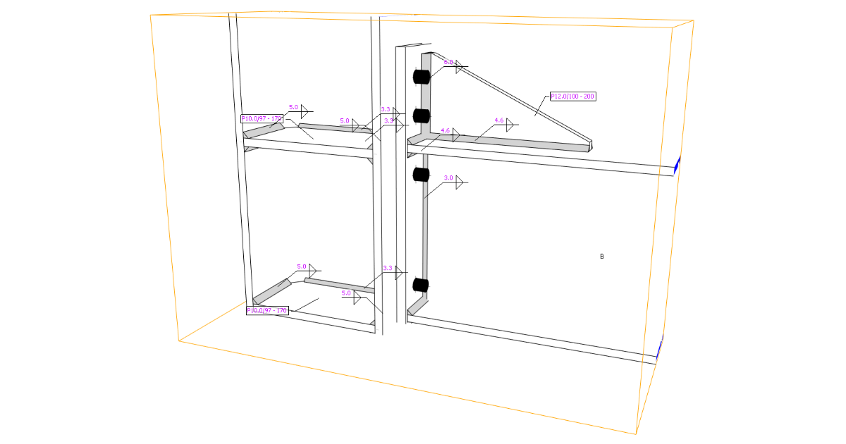
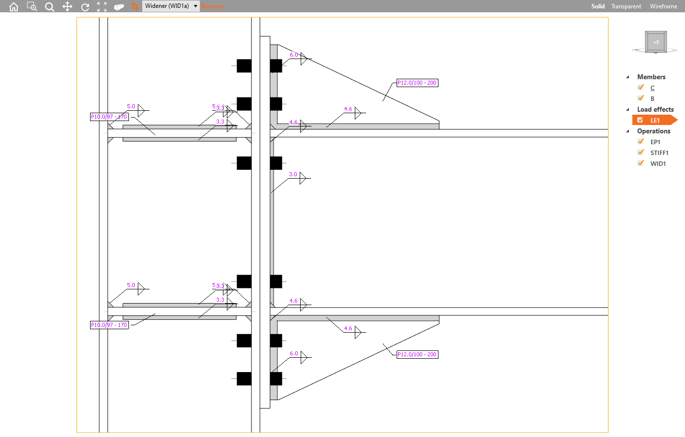
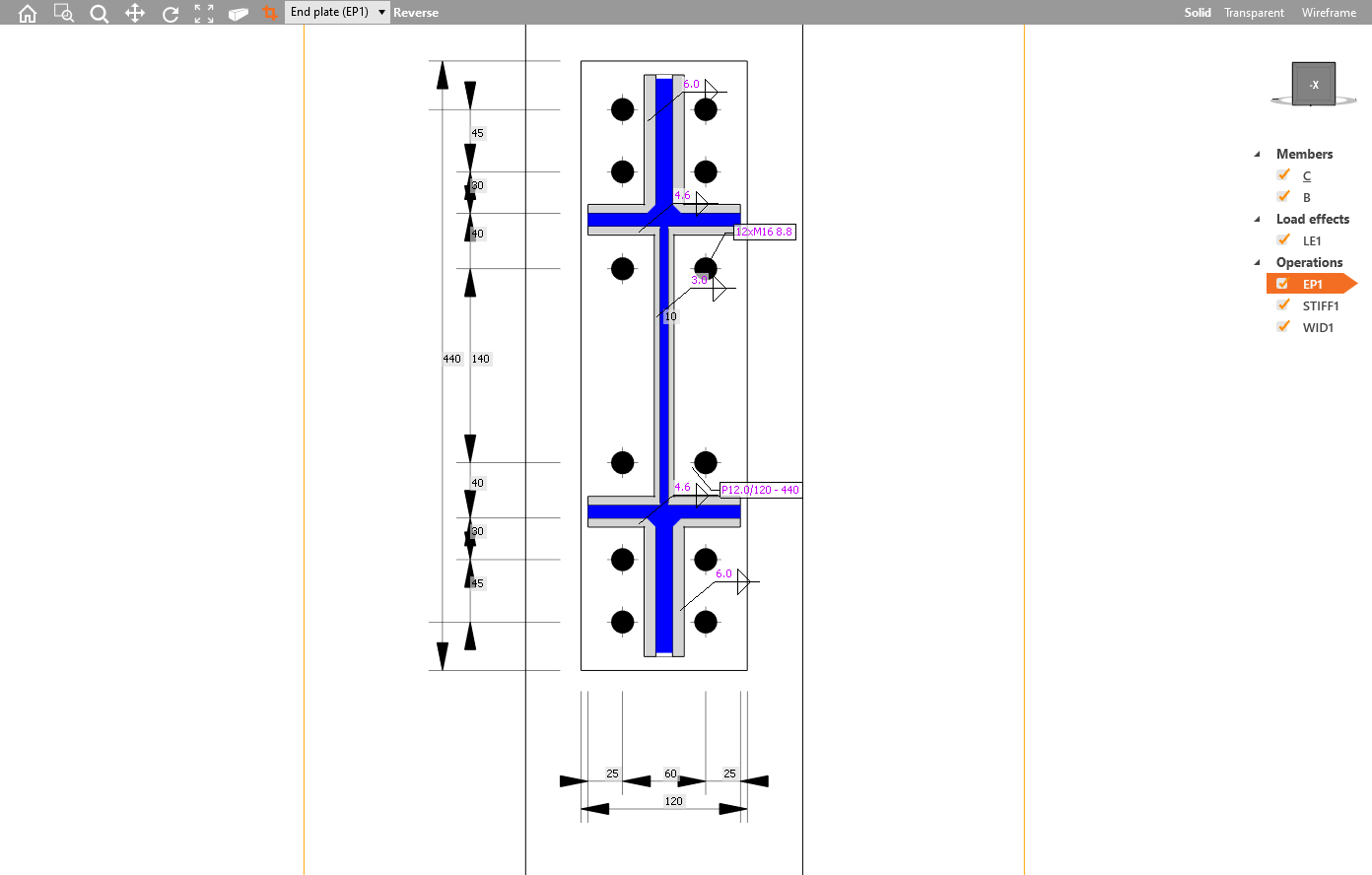
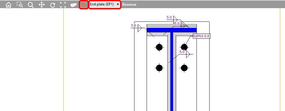
Section model view – drawings (“sketches”)
All structural engineers, designers, and detailers require clear visual outputs of their designs. That is why the possibility of drawings adjustments was a highly desired feature. Engineers want to generate “sketches”, detailers like to receive them, so they do not start the detailing from scratch. From now on, you can define and modify section models in the main 3D scene window.
Several section views can be defined, each of them must be attached to the plate, and the boundaries of the section or the section orientation can be modified.
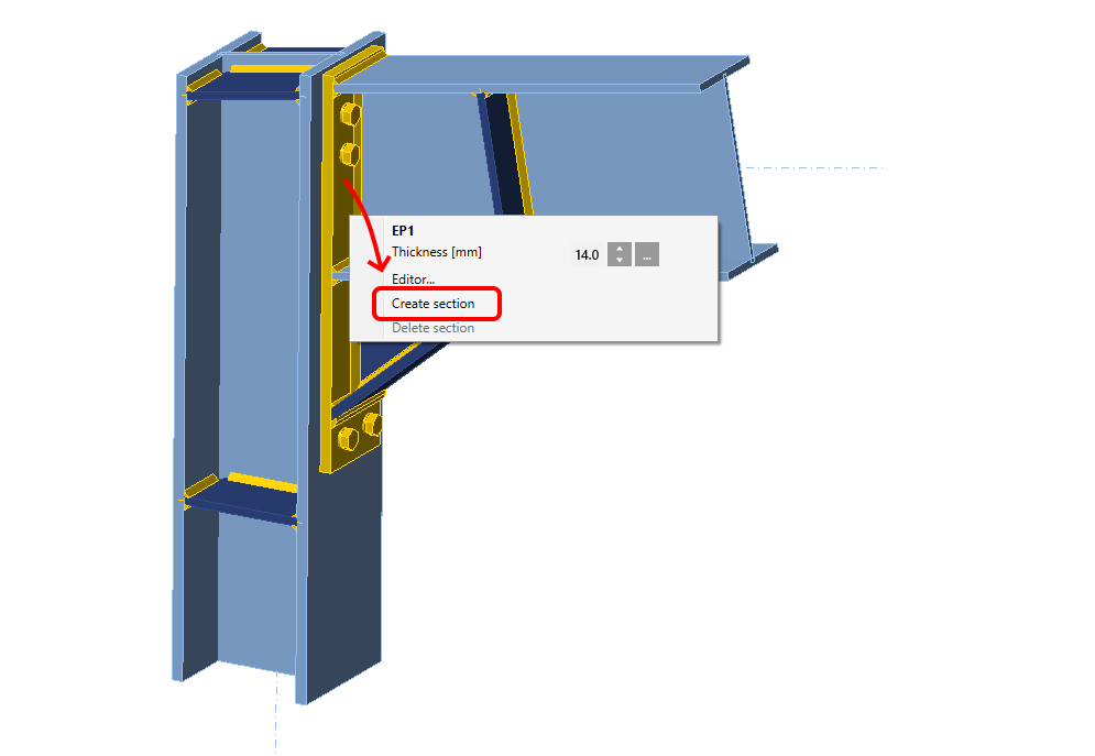
To add a new section to produce a drawing or sketch, select a plate in the connection model, and in the right-click menu select Create section. To delete it, select the plate and choose Delete section.
To exit the section view, click the icon Named section. You can access the section views afterward again using this icon and browse and modify all added sections in the menu.
Section model view can be printed to report or saved to a gallery for further usage.
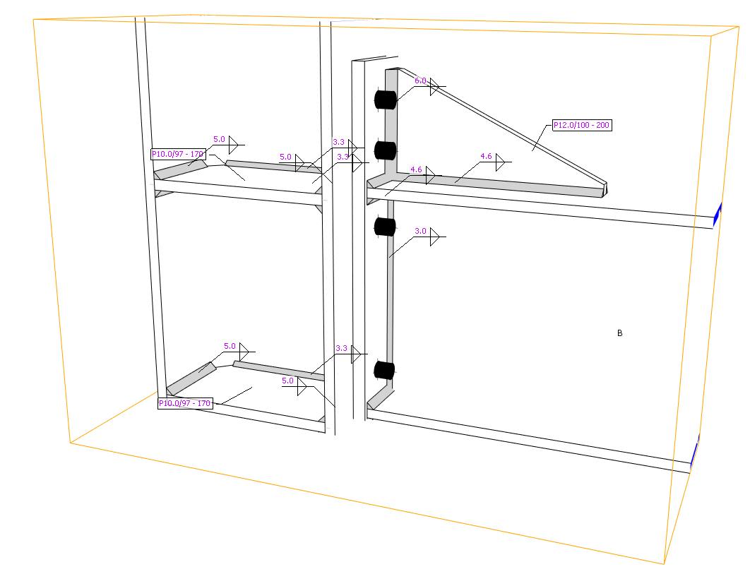
There is set an automatic generation of labels for welds and plates which describe the type and thickness of the weld and thickness/dimensions of the plate, respectively.
Weld labels and plate property label
This feature is available only in Enhanced version of IDEA StatiCa Steel
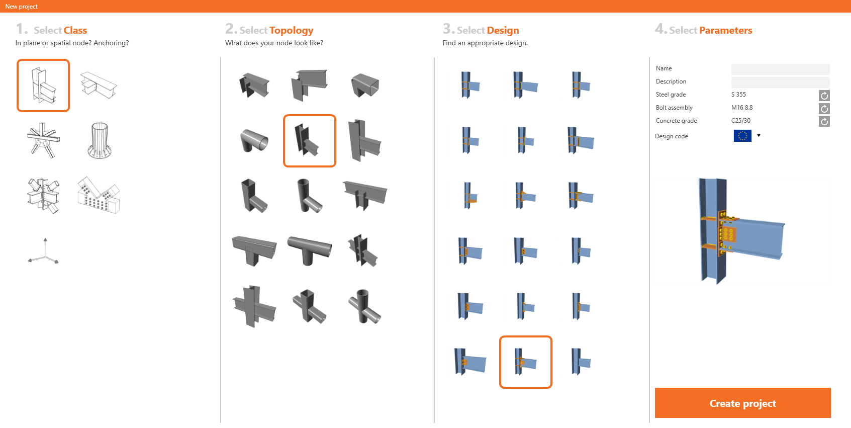
110 new connection templates in the starting wizard
IDEA StatiCa support team continuously gathers user requests for new templates. Result? 110 brand new connection templates that are available in the starting wizard of IDEA StatiCa Connection. Any template can then be further edited to achieve desired design parameters. This will help engineers all around the world to design hundreds of repetitive connections in seconds and spend their precious time figuring out the complex ones.
New templates in the starting wizard.
This feature is available for the Expert and Enhanced version of IDEA StatiCa Steel.
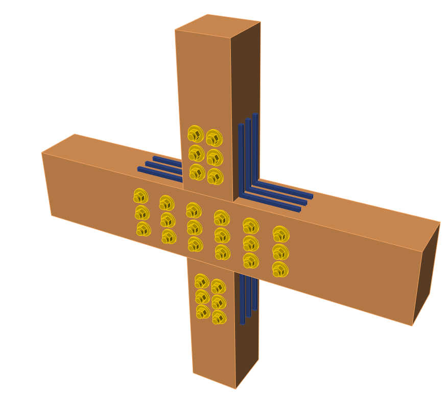
Timber connections (steel-to-timber)
Steel-to-timber connection design is another step of enabling users to design and code-check various types of connections and members from multiple materials.
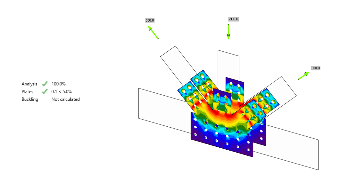
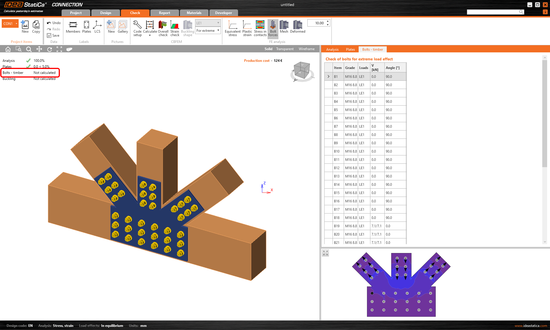
Example of steel-to-timber connections
Results on the connecting steel plates can be obtained. Code checks for the steel plates are available according to the chosen code. Code checks of timber members, bolts, and dowels are not delivered and must be performed by a third-party application. On the other hand, IDEA StatiCa Connection application delivers acting shear and tension forces on each bolt or dowel for the precise manual code-check.
See also the Theoretical Background article about Steel-to-timber joints.
Templates and manufacturing operations
Two new manufacturing operations were implemented for timber members – Gusset plate and Connecting plate. Users can make the selection in the Manufacturing operations menu.
Gusset plate and Connecting plate for timber members manufacturing operations
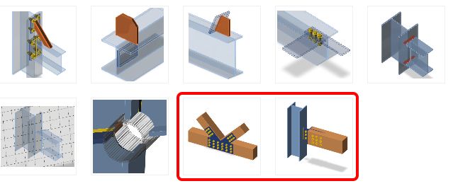
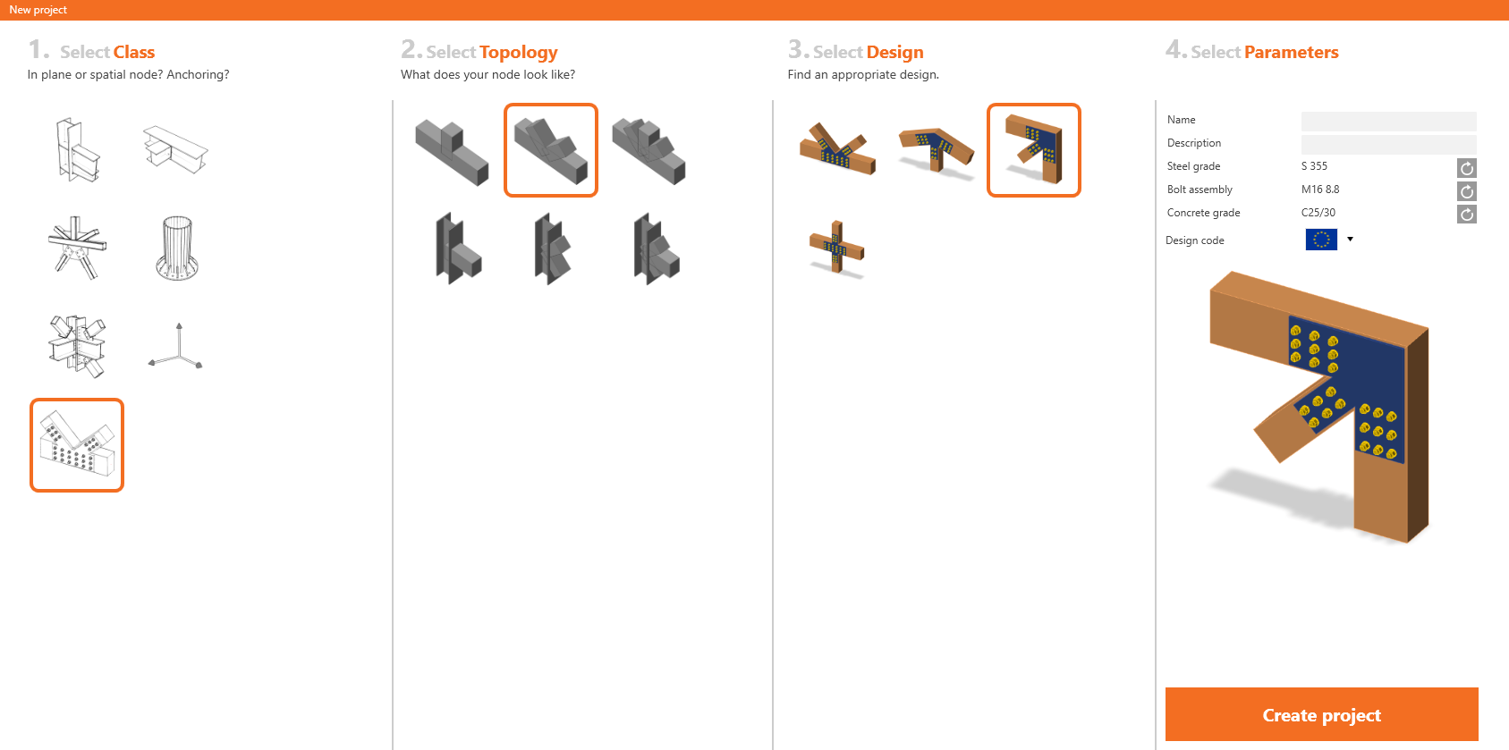
To help you with designing of steel-to-timber connections, new templates were added to the application wizard.
Steel-to-timber connection templates
Updates of the feature
Timber connections check was implemented in IDEA StatiCa version 20.0.
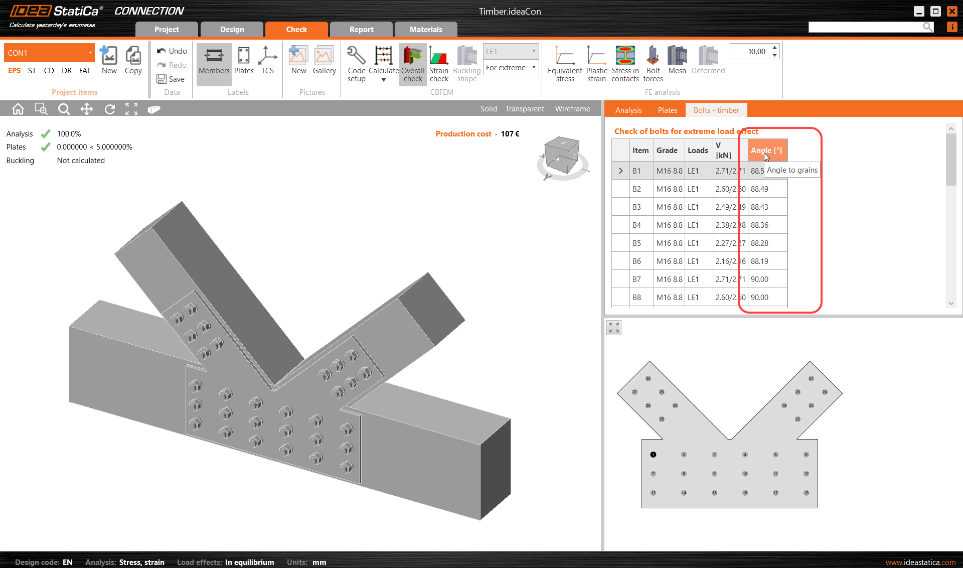
Since 22.0.1 patch, it has been possible to see the resultant grain angle for the bolt check. See the dedicated Release Notes 22.1 article.
Since 23.0.1 patch, the warning has been displayed to emphasize that the bolts going through the timber member are not checked (in the 3D scene and in Report).
This feature is available for the Enhanced version of IDEA StatiCa Steel.
Webinars and other resources
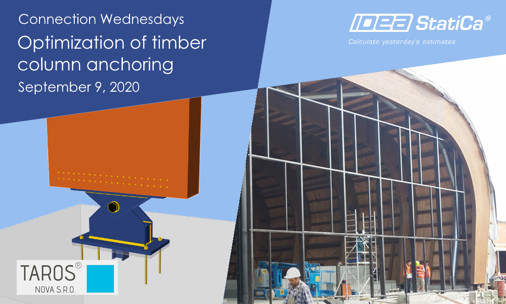
Check out the possibilities of the timber connections check in practice in the recording of the Connection Wednesdays - Optimization of timber column anchoring webinar.
In our blog, you can read an article about Designing steel-to-timber connections from July 2020.
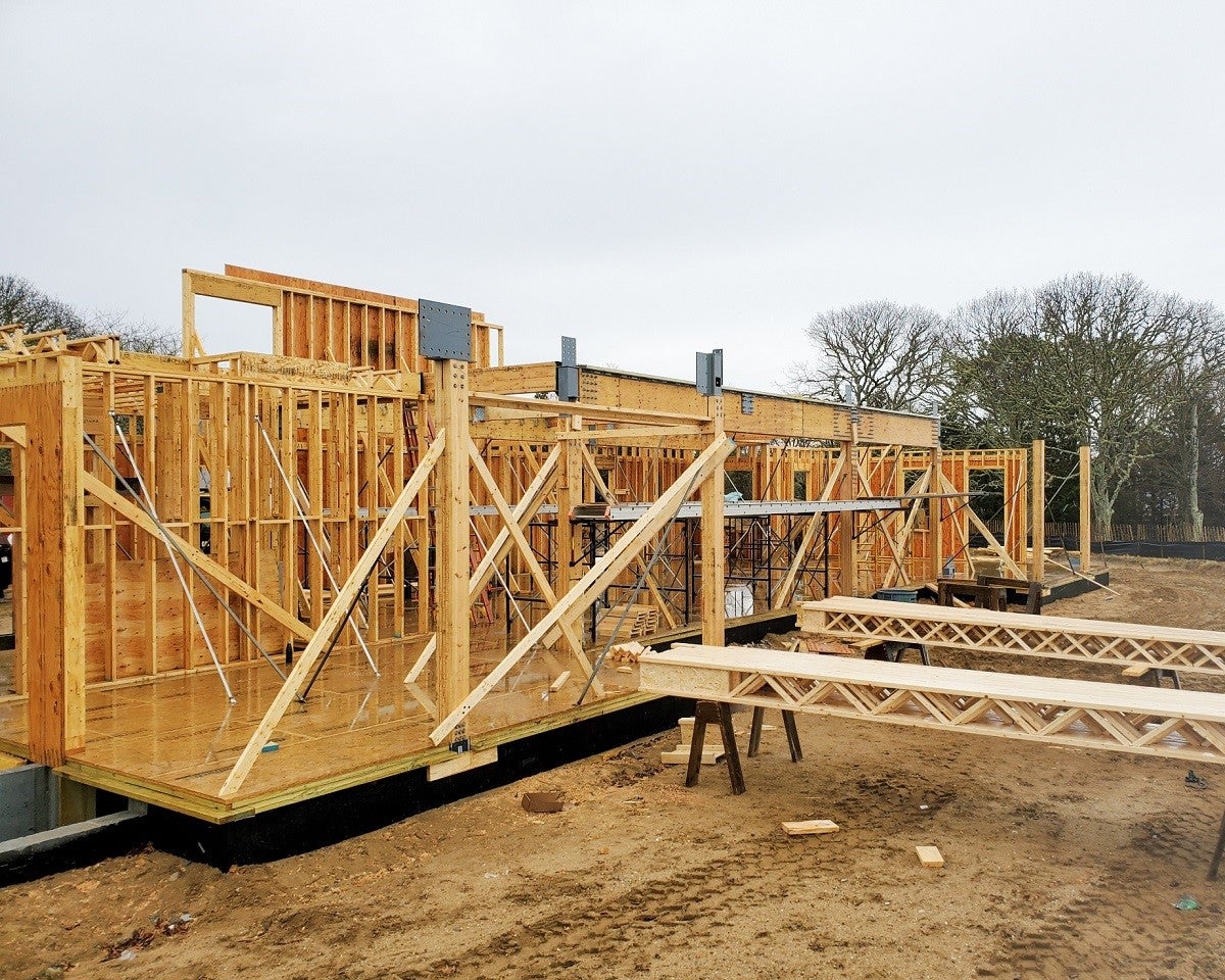
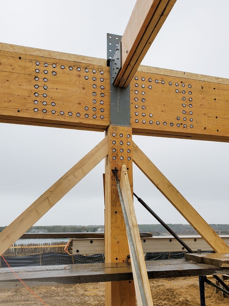
Take a look at the case study of a Family home in Massachusetts done by our customer - the CRAFT Engineers.
Related articles
Connection Wednesdays - Optimization of timber column anchoring
Cleat manufacturing operation improvements
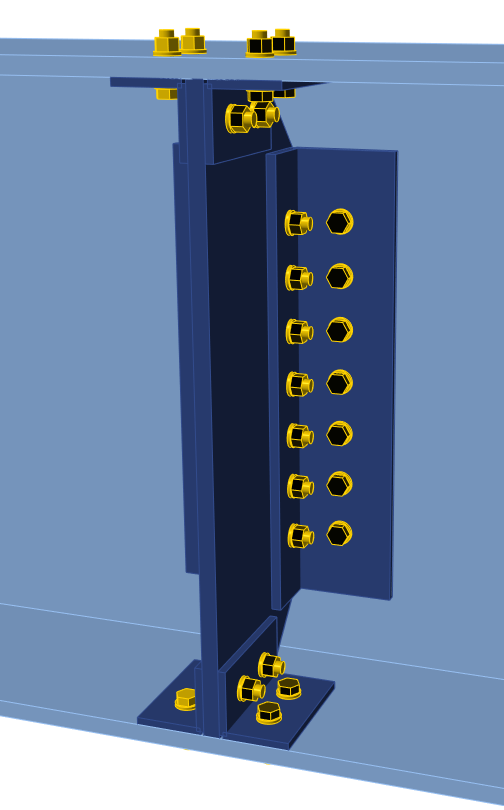
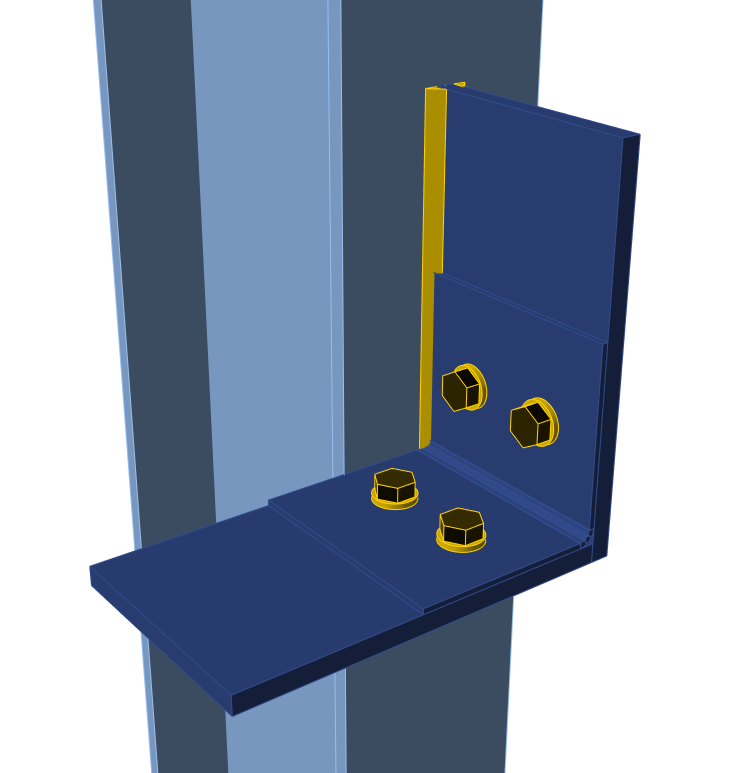
Cleat connections are popular among designers and engineers for their versatility. The improvements in Cleat manufacturing operations lead to new possibilities in the design of connections and joints. Any two perpendicular general plates cut each other can be connected by cleat and as well as any general plate and member plate.
Cleat examples: General plate connected by cleats to member.
Cleat examples: Two perpendicular plates connected by cleat.
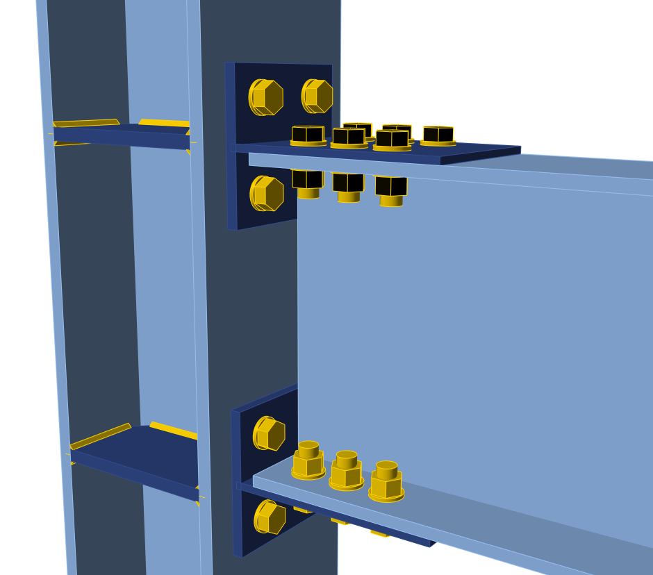
T-stub cross-section can be used to replace L-shapes in the Cleat manufacturing operation or to connect flanges and webs. Thanks to this, bolted connection types (used mainly in the US) can now be designed faster.
T-stub defined to flanges of the member.
This feature is available for the Expert and Enhanced version of IDEA StatiCa Steel.
Notch on a member
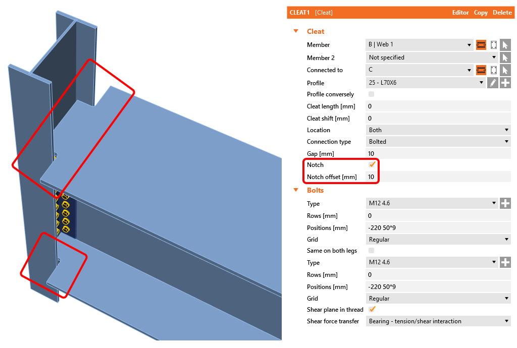
In the case of the members' clash, the opening-notches had to be defined manually by the Opening manufacturing operation on the member flanges. This situation was causing an increased quantity of manufacturing operations. From now on, the feature Notch can be used whenever it is needed to avoid clashes between column-beam or beam-beam. This feature is implemented to Manufacturing operations End plate, Fin plate, Cleat.
A notch at the flanges defined by the new feature.
This feature is available for the Expert and Enhanced version of IDEA StatiCa Steel.
Code check improvements
EN anchoring code-check improvement
In the previous version of IDEA StatiCa Connection, anchoring checks were performed according to the ETAG code. From version 20, the anchoring checks are compliant with the currently valid EN 1992-4. That leads to a more efficient design compared to the old ETAG.
Detailed results of anchor code-check according to EN 1992-4.
All formulas and values are provided in the detailed results tables.
IDEA StatiCa Connection 20 anchoring check summary:
| National code | Anchoring check |
| EN | 1992-4 |
| AISC | ACI 318-14 |
| CISC | CSA A23.3-14 |
| AS | AS 5216:2018 |
| SP, GB, IS, HKG | Not performed |
This feature is available for the Expert and Enhanced version of IDEA StatiCa Steel product.
Contact stress between two plates
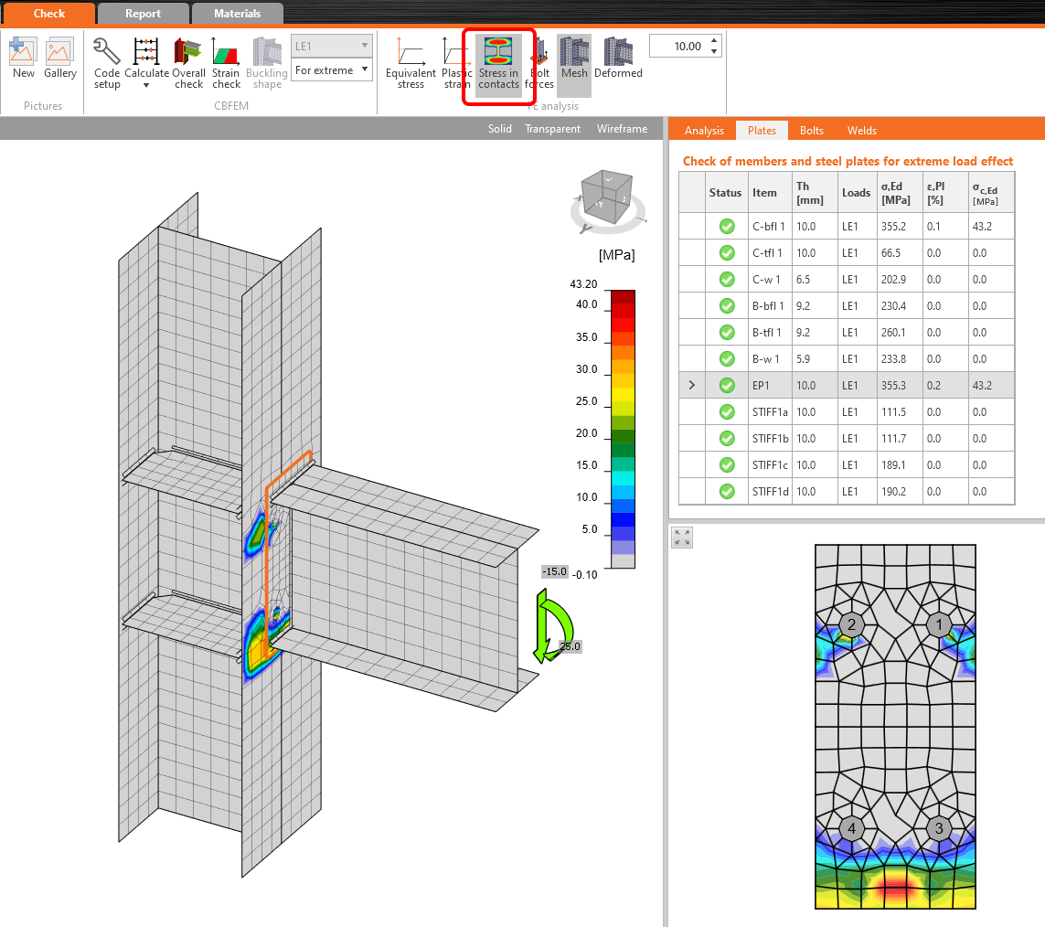
Contacts are defined automatically in case of a bolt group definition or manually by a manufacturing operation. From now on, the contact stress between the two plates can be displayed. This helps to better understand the connection behavior and better model validity control (prying actions, deformation, etc.).
Contact stress results between the end plate and the column flange.
The values are shown in the check table of plates. However, the contact stresses are only informative and are not used in any check. Also, the through-thickness stress of shell elements is not considered.
This feature is available for the Expert and Enhanced version of IDEA StatiCa Steel.
Partially supported base plate
Anchoring of the steel joints is now even more versatile, with the possibility to partially support the base plate or member.
General anchoring of the member with defined partial supporting concrete foundation block.
This feature is available for the Expert and Enhanced version of IDEA StatiCa Steel product.
Cross-section library favorites
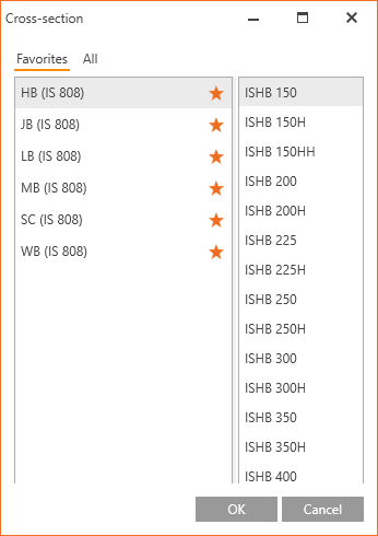
Cross-section library databases contain typical cross-sections for eight national design codes with a total count of more than thousand of items. That means a lot of possibilities for the design. But it can also make the process of listing and finding the desired cross-section awkward, especially for repetitive connection design. From version 20, the user can easily mark the desired cross-section family as a favorite one and let it get listed separately from the rest of the database. This speeds up the design process significantly.
User-defined favorite cross-sections.
This feature is available for the Expert and Enhanced version of IDEA StatiCa Steel product.
Regional-based item order in the cross-section library
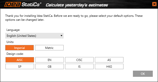
IDEA StatiCa automatically reorganizes the order of cross-section items based on the design code selected when launching IDEA StatiCa Connection. Thanks to this feature, e.g., engineers from the USA using AISC code will have the AISC relevant cross-sections in the first rows of the library. These settings can be set by all users individually across the organization to speed up the work of every engineer.
User preferences options which are available during the first start of IDEA StatiCa Connection.
This feature is available for the Expert and Enhanced version of IDEA StatiCa Steel.
Typical Taiwanese cross-sections
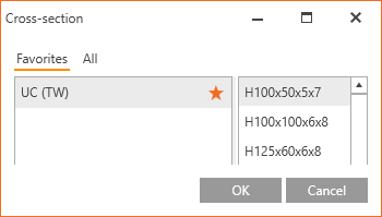
Typical Taiwan cross-sections were implemented in the cross-section library. The UC, L-angle, CHS, and RHS cross-sections with the marker (TW) are now available in the cross-section library.+
UC Taiwan cross-section in the library.
This feature is available for the Expert and Enhanced version of IDEA StatiCa Steel product.
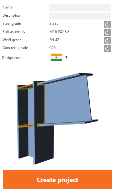
Indian design code (IS)
The Indian steel design code (IS) for steel-to-steel joints is now available alongside seven other design standards. Components bolts, preloaded bolts, welds, and concrete in compression are checked according to IS 800:2007 and IS 456:2000, including detailing.
Steel grades, bolt grades, and typical steel cross-sections are listed in the library.
Indian code and typical cross-sections
This feature is available for the Expert and Enhanced version of IDEA StatiCa Steel.
IDEA StatiCa Code-check manager
Unified GUI for CAD and FEA
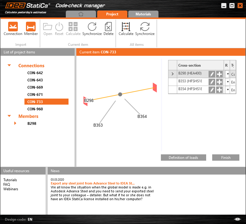
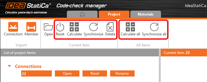
The user interface of the IDEA StatiCa application is the key to smooth everyday workflow. From now on, the user interface of the Code-check manager is unified for CAD and FEA applications, and it can be used to export, manage, recalculate, or synchronize all connection items or member items.
Code-check manager application.
Tekla Structures, Advance Steel and Revit
All CAD links are powered with the same technology now, and that allows us to improve the functionality in one push for all CAD applications. To IDEA StatiCa 20 was implemented a brand-new way of unsymmetrical cross-section beams import such as L-shapes, U-shapes, etc. Now the positioning of the cross-section is imported exactly how it is defined in the CAD application without further changes.
Multiple selection and export from FEA software
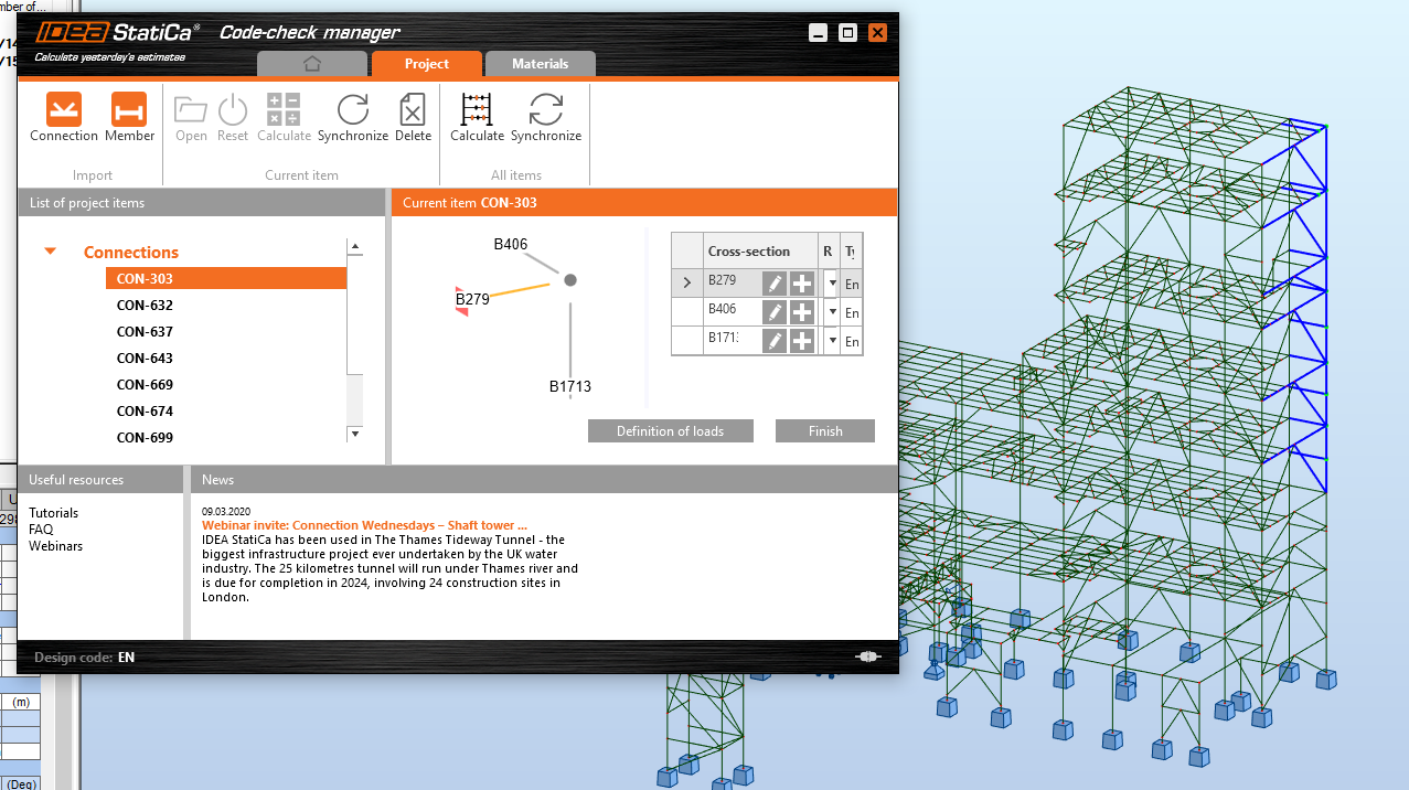
Import from FEA applications is now easier than ever, the user can select multiple nodes, and Code-check manager will import all of them as unique connections. IDEA StatiCa integrates automatically to your software during the installation, adding a new command to the ribbon.
By running this command, open the Code-check manager. Drag the mouse to bulk select the chosen nodes and click the Connection button to import all data at once. After opening and designing the imported joints one by one, you can run the bulk analysis to code-check all the connections at once.
Take advantage of the synchronization function - if you change anything (e.g. load combination, cross-section of a beam) in the structural model, at one click you upload the new data to all the joints on the list while you keep the design. Then click calculate all to check code-checks of the refreshed connection models.
This feature is available in any IDEA StatiCa Steel package. Mass Calculation and Synchronization of all listed items is available only in the Enhanced package IDEA StatiCa Steel.
Please note that for SCIA Engineer, the Code-check manager has not yet been implemented and the BIM link imports single nodes one by one only.
IDEA StatiCa Member BETA
The BETA version of IDEA StatiCa was a hit! It instantly becomes one of the most launched IDEA StatiCa applications. Based on the user feedback, we have improved various GUI and checking features.
Together with the university teams, we have finished the majority of verification and validation work. IDEA StatiCa Member MNA and LBA analyses are correctly tested in multiple experiments and examples. GMNIA analysis verification and validation for hot-rolled section members was tested as well. However, we must admit that the verification process is enormously laborious, and the job for welded section members is still in operation.
IDEA StatiCa 20 brings an improved version of IDEA StatiCa Member so that structural engineers can properly handle buckling and stability issues in varying complexity of steel projects.
To support smooth workflows, we implemented BIM links with several FEA applications – SAP 2000, ETABS, Autodesk Robot Structural Analysis, RFEM/RSTAB, and AxisVM.
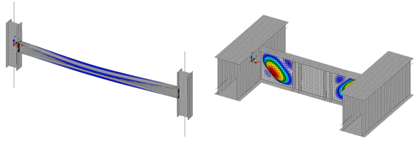
Global and local buckling simulated in IDEA StatiCa Member BETA
IDEA StatiCa Member is automatically available to all users with IDEA StatiCa Steel license, edition Enhanced. More information, tutorials, sample projects, and a lot more can be found on our Steel pages.
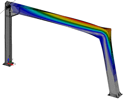
Buckling of a frame in IDEA StatiCa Member BETA
Manufacturing operations in the previous version of the Member application were limited. From now on, the full designing potential is provided with five new manufacturing operations such as the cut of a member, cut of a plate, stiffening member, general weld, and transversal stiffener.
IDEA StatiCa Member manufacturing operations.


