Highlights
Since the first release of IDEA StatiCa Connection in May 2014, we have collected a tremendous amount of feedback on how to simplify the application. Based on this, we developed a brand new graphical user interface (GUI) with a lot of new features that will help you speed up the design and code-check of the steel connections, especially the simple ones. The second biggest topic of customer feedback has been the BIM links so we developed a powerful tool for the management of the exported connections from CAD and FEA applications – we can now synchronize connection models in IDEA StatiCa and other applications. On top of it, there are several new features such as direct report export, new models for anchoring or stub manufacturing operation.
Calculate yesterday’s estimates with IDEA StatiCa!
GUI redesign
We developed a new GUI to simplify, clarify and update the “face” of IDEA StatiCa Connection. We took a deep look at every command, button, ribbon, etc. We discussed their usability and the context of the workflow. This enabled us to make room for a lot of new features to enhance productivity and accuracy.
Wizard for the New connection
The new connection wizard will help you to design and code-check new connections. Choice of Class, Topology, and Design from pre-prepared templates allows you to define hundreds of connection types in seconds. All items are available in EC, AISC and CISC codes.
Navigator replaced with the ribbon tabs
Five ribbon tabs replaced the left navigator window.
- Project – file menu for managing the project and the application in one menu.
- Design tab – modify or create members, their geometry, load effects, and manufacturing operations.
- Check tab – analysis can be performed and the results explored.
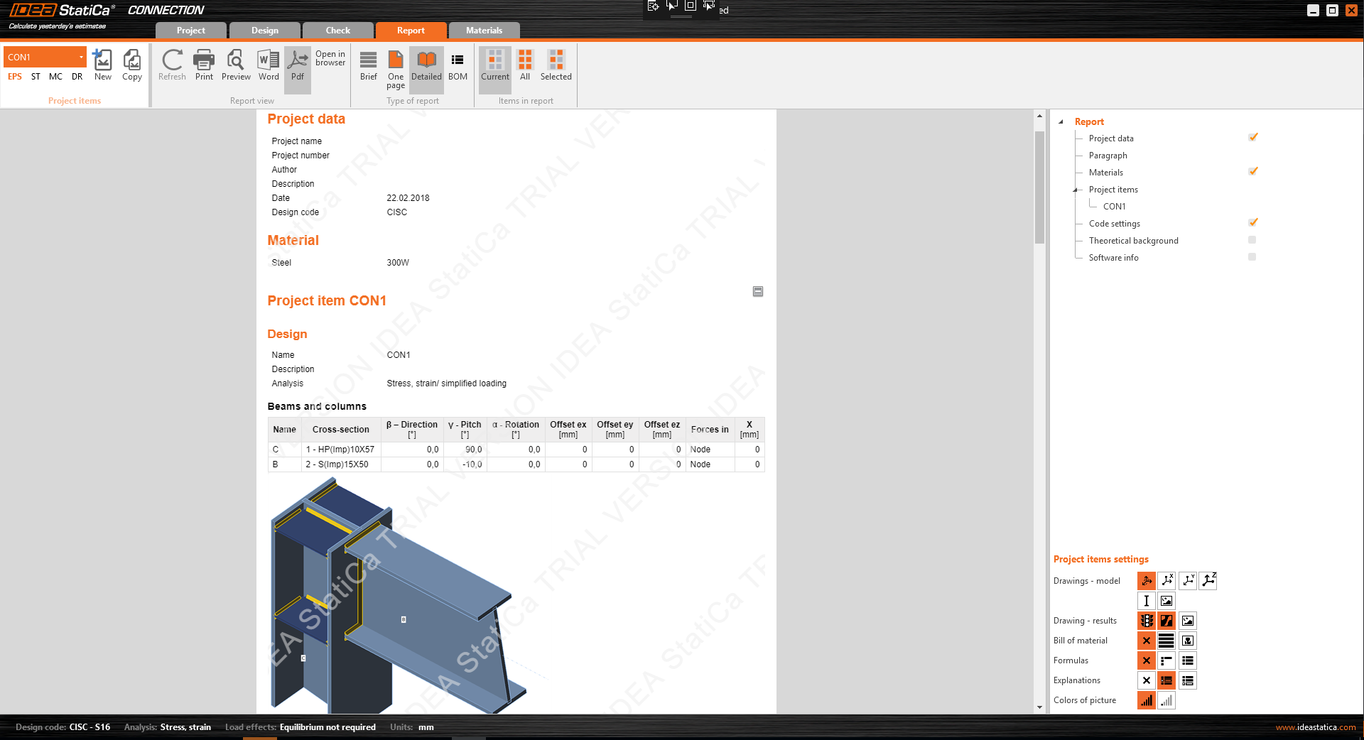
- Report tab – provides the protocol and bill of material.
- Material tab – information about the materials, cross-sections, bolt grades and assemblies are combined.
3D scene
- Updated technology for the visualization of the 3D scene
We updated the 3D scene rendering technology to the newest version. This leads to better, faster and smoother visualization (to tune up the visualization, enable the hardware acceleration and antialiasing).
- Tools for the 3D scene visualization style
The default home view, magnification tool, perspective, and several other tools are placed in the grey stripe above the 3D scene now. Easily available right above the main workspace.
- Tree of all entities in the 3D scene
One of the new controls in the 3D scene is the Tree of all model entities. In the tree, all members, load effects and manufacturing operations are available. This control can be used to effective orientation in the model, turning items on and off and edit of their properties. Don’t forget to use the right mouse button which can open the menu of other commands.
- Properties picking from the 3D scene
Properties defining the manufacturing operations can be picked from the 3D scene from now by the tool under the grey arrow symbol. Choose the command and then pick up the desired member in the 3D scene.
- Load effects visualization
Better load visualization together with input by a tree of entities gives an effective design workflow.
- Shear force position moved from Load effect to the member design
- Summary of results in the 3D scene
Analysis can be performed at the Design tab which leads to an effective way how to fine-tune the model. Results summary is provided in the 3D scene and traffic light feature too.
- Right mouse button commands
- Entities modification
Right mouse button commands can be useful in the 3D scene as well. You can modify the member cross-section, weld, bolt, and plate thickness.
Member entity:- Cross-section modification
- Set the member as a bearing one
- Set of command for defining one-member connection. For example, Clean command will delete all manufacturing operations related to the chosen member. Modify command will offer you a set of possible modifications such as openings.
- Entities modification
Plate entity:
- Thickness of the plate
Weld entity:
- Throat thickness
- Material of the weld
- Weld type
Bolt entity:
- Diameter and grade modification
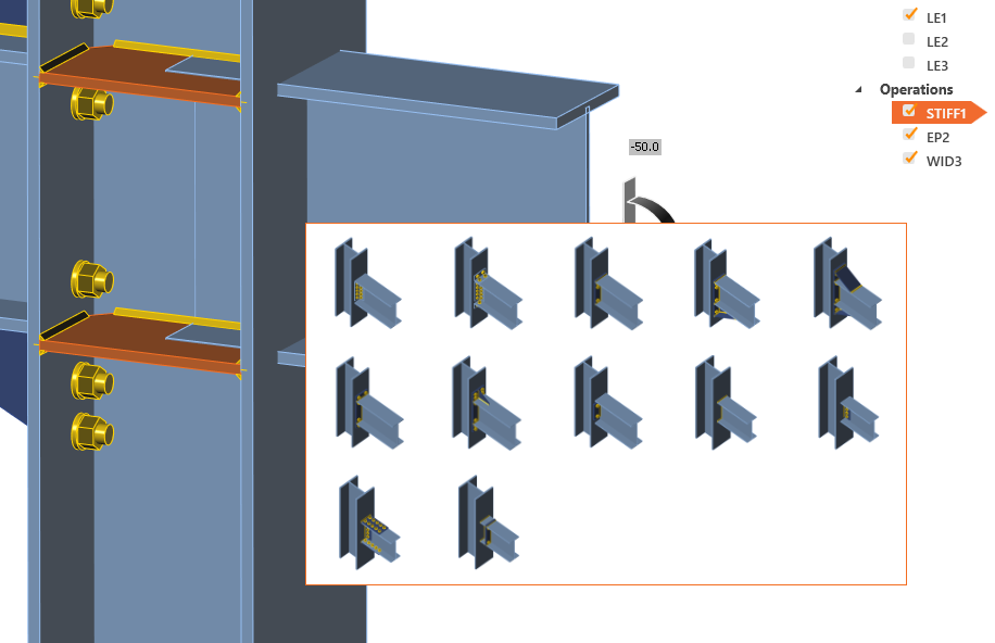
One-member templates
Connect command is available for the right mouse button click at member and it will create a one-member connection. In the first step, the face for the connection has to be selected and then the set of one-member templates is offered.
Bill of Material in the Report tab
Together with the new tabs, the Bill of Material (BOM) was united to one command in the ribbon. It can be found in the Type of report family.
Material and cross-section libraries joined to the Material tab
Similarly, to the new tabs, cross-sections, bolt grades, bolt assemblies and material properties were united.
File menu
The File menu was developed to help you manage the project and application in one menu. Item Information replaces the Project items in the past versions.
Auto model control, warnings
- Singularity warning
The singularity check of the model was implemented. New status in the results summary is printed and there is a model with exploded items provided in the 3D scene. In the example below, you can see the nonwelded member.
- Member length
The default length of the members is calculated automatically. There is no need to change the length of the member manually anymore. The algorithm will increase the length of the member after definition of manufacturing operation.
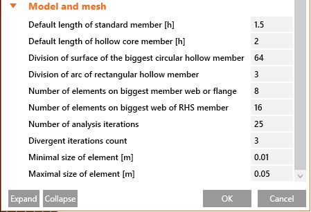
- Surface division of the hollow structural members
Due to the better results for the hollow cross-section members, a dedicated setup value for the mesh and division properties are created.
Opening older models in version 9
One of the reasons behind the new GUI is that a lot of engineers were telling us: „IDEA StatiCa Connection needs to be more error-proof”. These “errors” are usually related to:
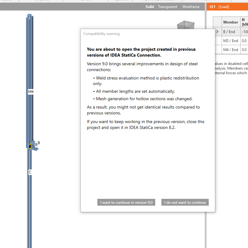
- Setting the correct length of members – in cases of extremely short or long members, this can hugely influence the results. In version 9, IDEA StatiCa Connection automatically sets an appropriate length of all members.
- Welds – stress plastic redistribution is by far the most accurate design method for welds and was introduced in version 7.1. During version 8 – and as a transition period - it was the default method, coexisting with the other evaluation methods. In version 9, this method is the only option available and the other evaluation methods have been removed, to avoid confusion among the users, as we have seen through our helpdesk. This ensures that all welds in the project are safely designed and complying with the code.
We have implemented several control mechanisms for IDEA StatiCa Connection version 9 – automatic control if the connection is modeled in a recommend way (singularity check, member lengths, their offsets, …). If the connection is not modeled properly, the calculation is interrupted or an error message is displayed. Please be aware that because of all of these improvements, opening projects from previous versions can lead to a different model geometry that may need some further editing.
We have also improved meshing of hollow sections members – IDEA StatiCa Connection version 9 generates a finer mesh on hollow section members which might lead to slightly different results compared to older versions.
We display the compatibility warning on each opening of a project from an older version:
IDEA StatiCa Connection 9 is a tool that can design and check connections of any topology and loading. And on top of it, it gives clear recommendations/limits on “how” to do it and what to avoid in connection design. This ensures safety and consistency across all stakeholders involved in the design process.
BIM
Until version 8.2 we have developed 15 BIM links with various FEA/CAD applications. And those links are one-way, i.e. simple export of the data from FEA/CAD applications into IDEA StatiCa.
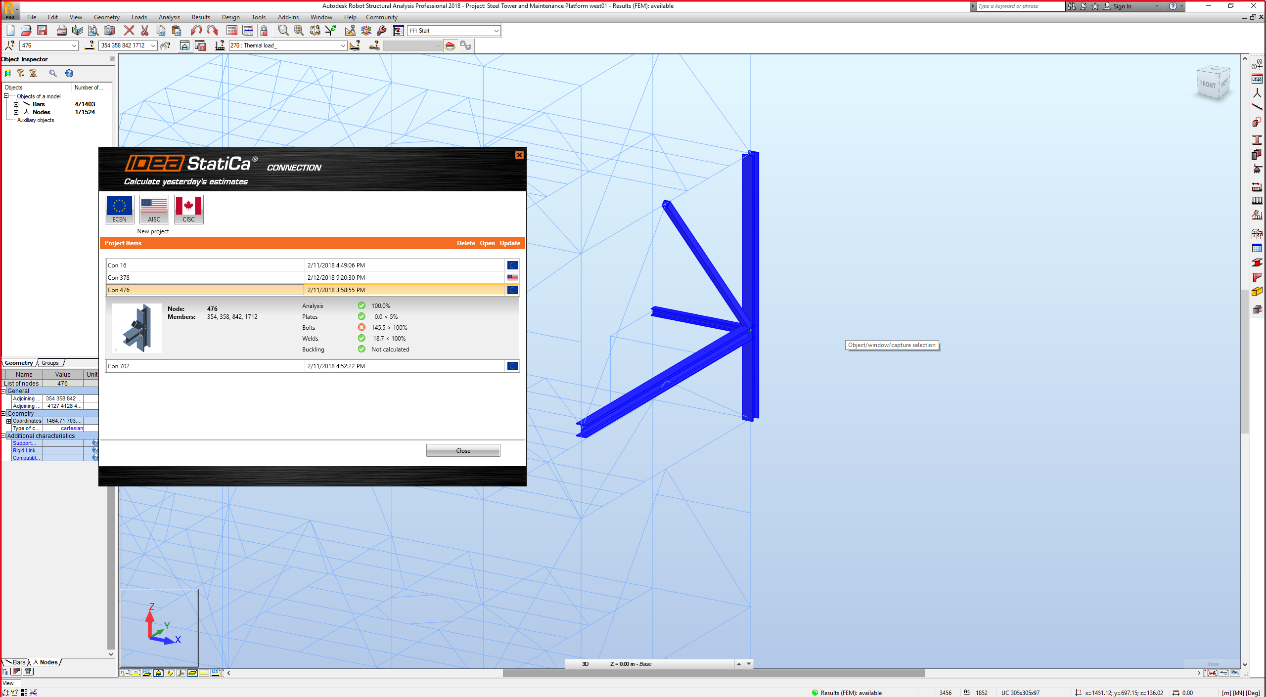
Version 9.0 brings a big improvement of this workflow – we are now able to automatically update the IDEA StatiCa model according to changes in the original FEA/CAD model. We have also implemented a clear way to manage all IDEA connections/beams exported from a particular FEA/CAD model – they are displayed in a window of a Connection manager with result overview (small picture, result summary, code, etc.).
To visualize your design, we have also implemented an automatic highlighting of selected connection in FEA/CAD application – you immediately see the basic overview of that particular connection in SAP 2000, for example.
CAD links (Tekla Structures and Advance Steel)
Until now, we had to export the connection from TS/AS to a new project every time. This meant inputting the load effects again.
Version 9.0 changes this dramatically:
- We create a steel connection in TS/AS
- We export it to IDEA StatiCa, input loads and perform a code-check
- Let’s say we want to optimize/change the connection design – we go back to TS/AS and do the necessary changes (bolt positions, weld thickness, add a stiffener, etc.)
- Then we click the “Update” button in IDEA plugin embedded in TS/AS and all the changes are automatically applied in our IDEA StatiCa project – no need to input the load effects again manually
- We can repeat this several times to optimize the design while making sure that all the data is correctly inputted in both TS/AS and IDEA StatiCa
FEA links (SAP 2000, Robot, STAAD.Pro, etc.)
Until now, we had to export the connection/beam from FEA applications to a new project every time. This meant to design the connection again.
Version 9.0 changes this dramatically:
- We select a node in FEA application
- We export it to IDEA StatiCa (geometry, cross-sections, load effects), design the connection and perform a code-check
- Let’s say we want to optimize/change the connection design – we go back to FEA application and do the necessary changes (loads, cross-sections, etc.)
- Then we click the “Update” button in IDEA plugin embedded in FEA applications and all the changes are automatically applied in our IDEA StatiCa project – no need to design the connection again manually
- We can repeat this several times to optimize the design while making sure that all the data is correctly inputted in both the FEA application and IDEA StatiCa
Miscellaneous
Plastic redistribution in the welds as a default method for the weld stress evaluation
If an elastic material model for welds was assumed, the finite element model would provide peaks at some locations of irregularities (ends, where 2 welds meet...). The weld capacity would be reached very fast at these small locations of peak stresses. That would mean the weld has very small load resistance compared to traditional hand calculation. Therefore, some kind of averaging is necessary. We used to provide the average for weld length (suitable for the flange in the example of the bended wide flange beam), linear interpolation (suitable for the web) or maximum (very safe). The user could make his choice, nevertheless, it required an understanding of traditional weld design and finite element design. Furthermore, the use of average value could lead to unsafe design in some cases.
Therefore, we decided the software needs to do the averaging correctly and automatically and after a lot of trials and testing, we developed plastic redistribution in welds. A solid element is inserted between the interpolation links. The plastic redistribution is there to correctly determine the resistance of the weld component by redistributing stress peaks into further weld elements. The most dangerous areas were recognized as welding to unstiffened flange (EN 1993-1-8 - Cl. 4.10). AISC and CISC use a different approach for weld design and require a reduction for multi-oriented welds. We focused on this issue as well and developed a special weld material model for AISC and CISC. Plastic redistribution does not mean allowing extreme deformations of the weld.
Plastic redistribution in the welds is the default and the only available method for the weld stress evaluation since version 9.0.
Export of the report directly to .doc and .pdf
We implemented the direct export to Microsoft Word (doc) and Adobe Reader (pdf) file types. From now, the export can be done only by one command.
AISC and CISC code requirement updates
- Improved material diagram for plastic redistribution of stresses in welds.
- Improved properties of a nonlinear spring element for the interaction of shear and tensile forces in bolt in bearing – tensile/shear interaction.
- Updated anchorage design.
- Anchors creating a common concrete cone are now assessed as a group which allows an increased resistance.
- Anchors at one base plate are checked as a group for a concrete breakout in shear. Only the anchors near the edge in the direction of shear force are assumed to transfer full shear force acting on the base plate.
- If a concrete breakout check is not required by the user, it is assumed that the tensile and shear force is transferred via concrete reinforcement. The user is provided with an aggregated force including prying forces that need to be transferred via reinforcement.
AISC formulas in results
Major improvement of the provided code-check formulas has been made. All formulas are explained now and the values are provided also.
Anchoring
- A new model for the shear lug
The shear lug mesh is now created in the same way as the mesh of members. 2D finite elements – plates are connected to the base plate with weld elements. The shear lug itself can be positioned and rotated in the baseplate plane without any limitations.
- Assessment of the welds and concrete in bearing
Checks of the concrete in bearing and the checks of the welds in the same way as checks of the welds anywhere in the connection was implemented to the result tables.
- A new model for the anchors with stand-off
Heavily loaded anchors with stand-off are equipped with two plastic hinges to allow more realistic force distribution.
Stub manufacturing operation
Major improvement of the Stub manufacturing operation was implemented. Now, the stub itself can be modified properly. The cross-section of the stub can be set independently on the main member and can be positioned with off-sets to the main member.
Default mesh settings for hollow section (CHS and RHS)
The default mesh setting for the hollow section members was improved. The mesh size of the member with the largest diameter is using default settings from Code setup and the mesh of smaller members is modified in dependence on the member diameter. The aim is to create the same mesh size on each of the members which increase the accuracy of the results.
Social share button
The right-click into the 3D scene opens the Share on LinkedIn or Facebook command. The actual picture from the 3D scene will be posted on your social media account (login is required).
Framework for trial and academic version
- Trial version
A new approach for the trial version was implemented. 14-day trial codes will be sent out automatically to each prospect after filling out a form. Hardware signature will be implemented so that prospects can activate only one trial at one particular PC or laptop. During the activation, we will read the hardware info (this is how AutoCAD and another SW do it). The background of the report and various scenes of the software will be watermarked. A new expiration countdown is placed on the top of the main window.
- Educational version
A new approach for the educational version was implemented. 365-day trial codes will be sent out to each prospect after filling out a web form. The background of the report and various scenes of the software will be watermarked. Only a PDF printout with a watermark is possible.
Projects from the Educational version cannot be opened/used in the commercial version (they will be permanently “marked” and limited).


