Steel joints of hollow section cross-section members
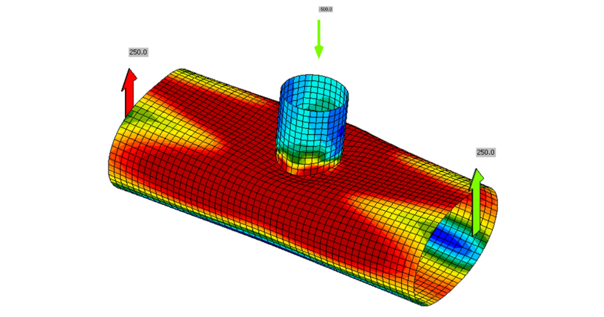
Joints of hollow section members may undergo serious deformations while able to carry still higher loads. On the other hand, the plates may buckle in inelastic range, for which purpose, geometrically and materially nonlinear analysis is implemented.
Out-of-plane deformation
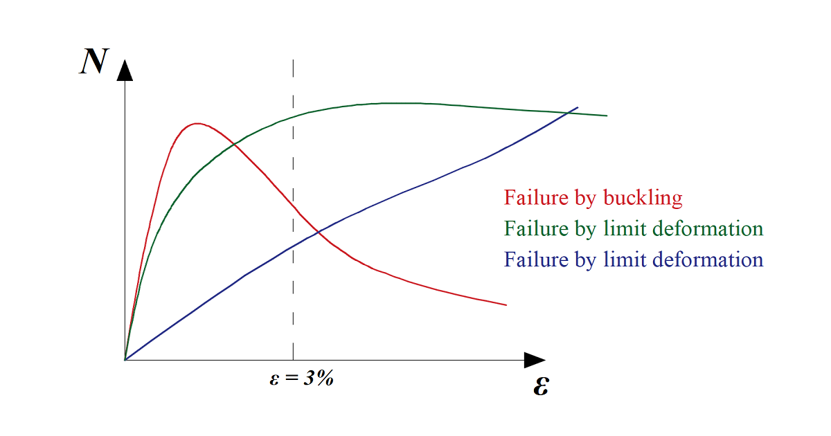
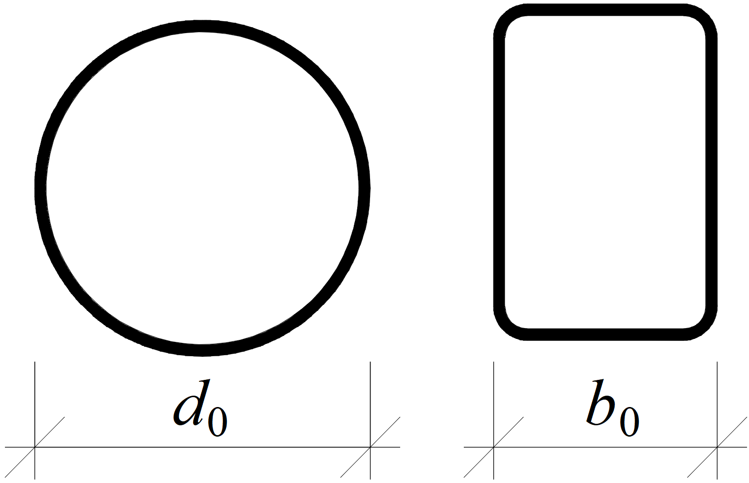
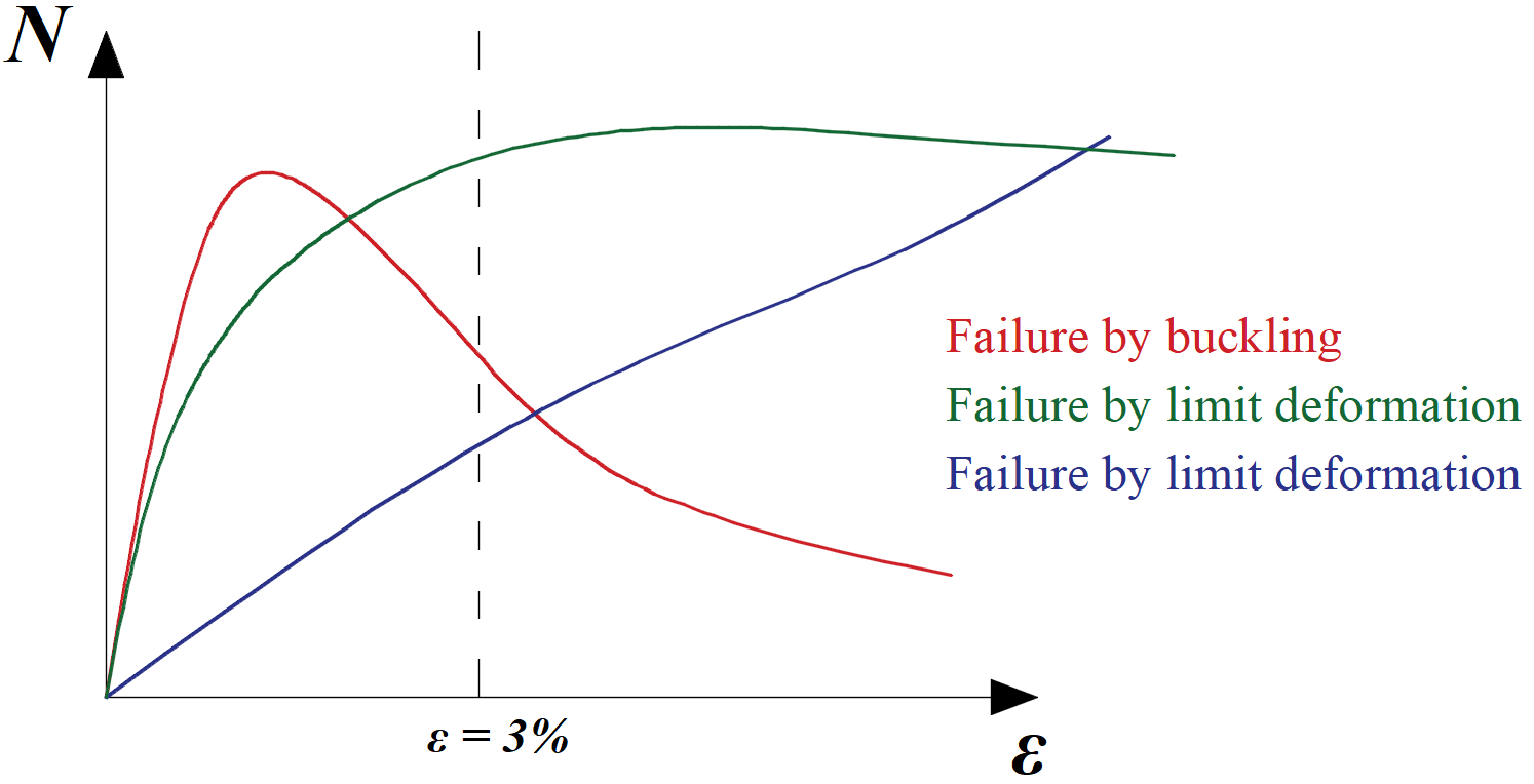
One of the criteria for the ultimate limit state of hollow section joints is the out-of-plane deformation of the hollow section cross-section. The check is available in the software (in Code Setup as Local deformation check, for hollow bearing members turned on by default). It is recognized by CIDECT design guides. The limits are 3 % of the smaller size of the cross-section (0.03 d0 for CHS and 0.03 b0 for RHS) for the ultimate limit state and 1 % for the serviceability limit state.
Definition of cross-section sizes for circular hollow section (CHS) and rectangular hollow section (RHS)
Typical load-deformation diagrams for hollow section joints; the red curve is for thin-walled member loaded in compression, the green curve for regular members loaded in compression, the blue curve is e.g. for X-joint loaded by tension
Geometrically and materially non-linear analysis (GMNA)
In the case of some joints of hollow sections, especially with high diameter to thickness ratio, the geometrically linear analysis may not capture the behavior of the joint with sufficient precision, and its load resistance may be underestimated or overestimated. It is recommended to use more advanced geometrically and materially nonlinear analysis for joints of hollow sections even though the computational time is slightly higher. If GMNA analysis for hollow sections is selected in Code setup, GMNA is used instead of geometrically linear and materially nonlinear analysis (MNA, used as a standard in IDEA Statica Connection) for models with hollow section member as a bearing member.
Note: If the bearing member is not a hollow section, the GMNA solver is disabled for the analysis of the whole connection model regardless of the settings in the code setup (GMNA on or off).
Cross-section deforms at the end of the shell model
The cross-section may deform at the ends of the model consisting of shell elements. Joints of hollow sections require relatively long members – up to 10 times cross-section diameter. Condensed superelement is placed behind the part of the model consisting of shell elements. This allows faster calculation with the same precision as the full model consisting of shell elements. The condensed superelement has only elastic material properties, and that means the plastic strains due to the investigated failure mode should not reach the end of shell element model. For this reason, the shell model spans by default 1.25 times the cross-section height (editable in Code setup) behind the last manufacturing operation.
Shell bending resistance reduced for hollow sections (imperfections)
Load resistances of hollow section joints in the codes are determined by the Failure Mode Method that uses curve-fitting models determined from experiments and advanced numerical models. The real structure contains initial imperfections and residual stresses, which are not captured by shell models in IDEA StatiCa Connection. To achieve closer compliance with the results of codes, the influence of residual stress and initial imperfections is simulated by reducing the bending resistance of shells of hollow sections with a high D/(2t) ratio.


