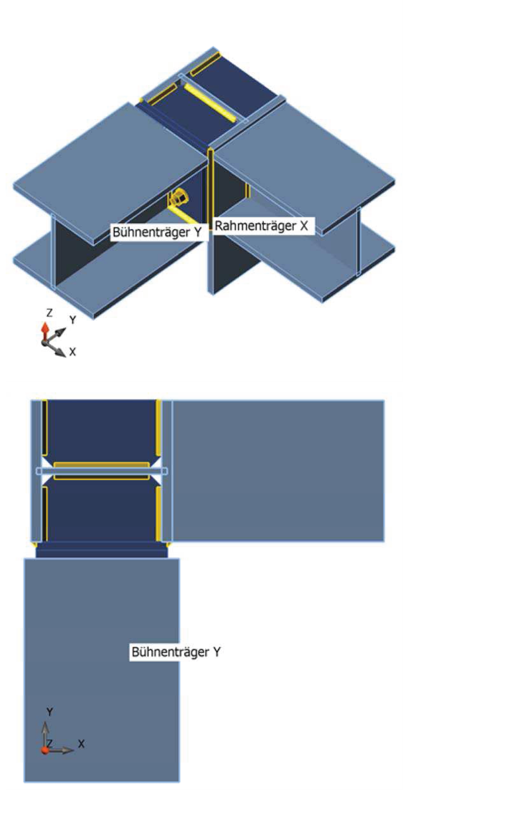
Supporting structure of a conveyor belt, Germany
Monath is a medium-sized engineering company active in all areas of structural engineering. In steel projects, most of their work is in industrial and warehouse structures. However, smaller steel construction projects with complex structural systems are also a challenge.
Motivation
Often, we have to work with non-standard connections (topology, cross-sections) and provide a thorough code-check. In the past, we were limited to basic connection design programs or calculations by hand. This limited our capability to evaluate the design properly.
The biggest problems arise with connections that are exposed to multiaxial loads where simulation in 3D is necessary. Here is where basic connection design software comes to its limits as only two-dimensional modeling is possible. Another problematic area is joints with very complex topologies. Our previous software for connection design was limited to predetermined types of connections (beam topology, profiles, cross-sections, stiffening plates).
Since these problems occur in our everyday engineering practice we decided to work with IDEA StatiCa Connection.
Advantages
IDEA StatiCa Connection has a very simple and clear working interface. In a short time, you find the way around in the program and get your work done quickly.
The CEA software used at Monath is SCIA Engineer. IDEA StatiCa Connection has a BIM interface which can import selected nodes (connections) from SCIA Engineer (including cross-section parameters and internal forces). This interface works very well. All important values (geometry and loads) are transmitted quickly and reliably, saving the additional input, time and effort. Of course, a separate input of the geometry and the loads is possible, so that individual checks can be performed independently of other programs.
Another advantage is the variety of design options. It is possible to adapt the joint according to project specifics and thus visualize a very realistic model. There are numerous manufacturing operations available, such as connections with end plates, connection plates, angle plates and much more. The biggest advantage is that a node with several different connection types can be modeled and immediately displayed in 3D. This allows almost any connection to be designed and verified no matter how unique it is.
In many structures, multi-axial forces are applied on the connections. In most programs, however, only a 2D calculation is possible. So, the connection must be labor-intensively evaluated only by hand - and multi-axial influences are simply neglected. IDEA StatiCa Connection enables the input of forces at the connection part as well as at the connected component. That means a realistic mapping is possible and the results are more accurate than with conventional calculation programs. This allows an unprecedented optimization of all connection properties (thickness of the plates or welds, etc.).
We use connection checks in accordance with Eurocode 3 which are displayed immediately. In addition, we also get internal stresses and forces, local buckling results and stiffness analysis (all based on an automatically created FE model).
Disadvantages
Besides the many advantages of IDEA StatiCa Connections, we also noticed some disadvantages.
Due to the dividing into several load cases, the calculation can take some time (for complex connections even several minutes). This is especially noticeable if the designed connections are pinned because in this case a lot of iteration steps have to be performed. The design of pinned connections, in general, requires a bit more experienced user in our opinion. We also see room for improvement in the output. For example, the position of plates, welds or screws is harder to recognize due to some missing dimensions.
Examples
In order to demonstrate our areas of application for IDEA StatiCa Connection, two examples from our projects are presented and explained below.
Example 1: Billboard structure
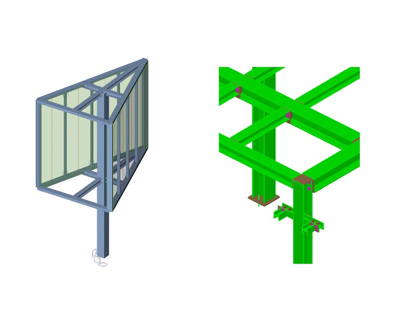
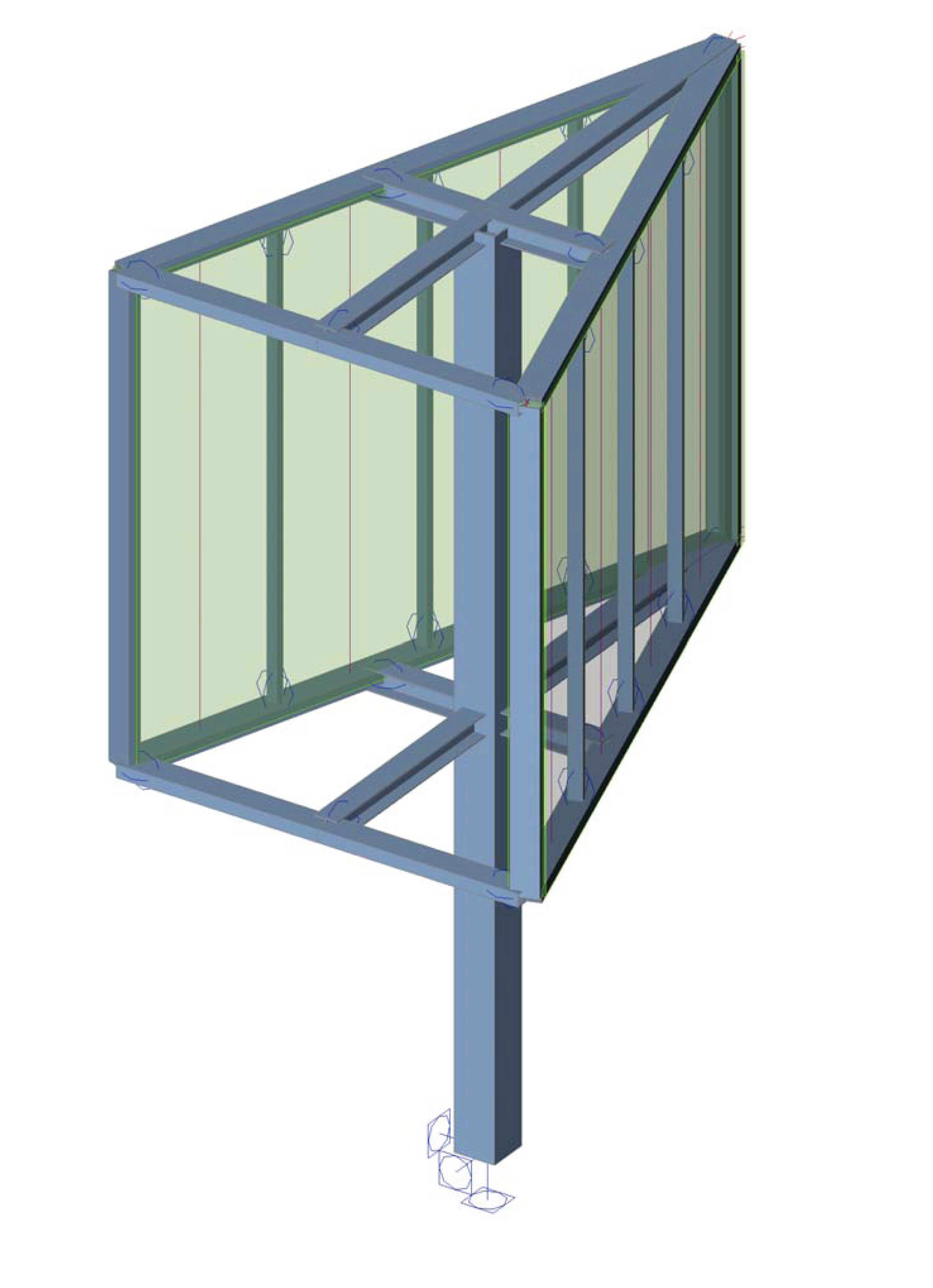
The first presented project is a billboard structure. The task here, in addition to various connections of hollow profiles, was to code-check the anchoring of the foundation.
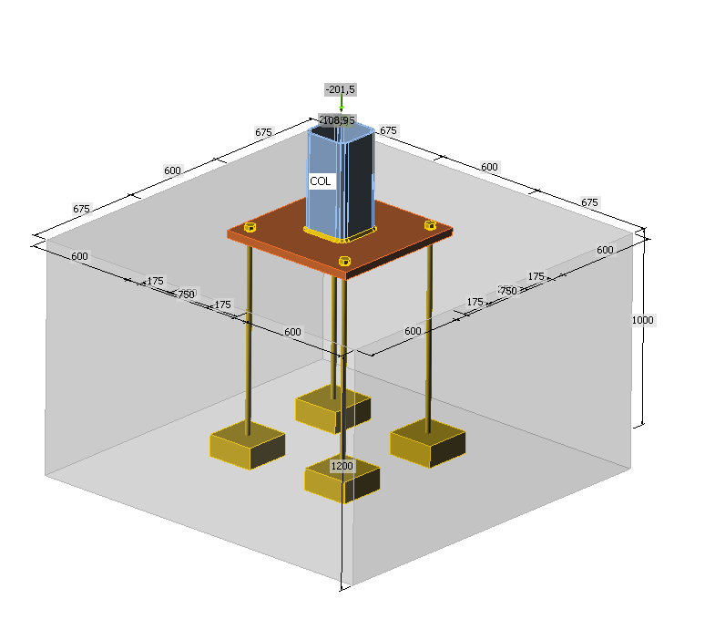
Wind loads moments and shear forces influenced the structure in two directions. The footing was, therefore, a complex connection, given the fact that other programs do not take moments around the X or Y axis into account. Using the BIM link from the CAE software SCIA Engineer, the cross-section parameters, as well as the internal forces on the node, were transferred to IDEA StatiCa Connection. Subsequently, the anchoring including welds could be modeled and checked, as shown below.
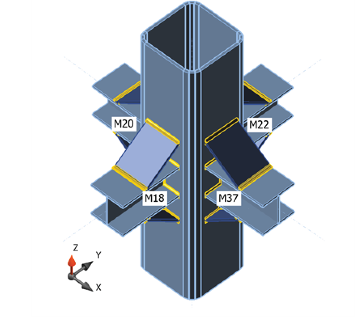
Another problem in this project was the connection of the main girders to the column. Using conventional calculation programs, such a structural system had to be simplified to a two-dimensional problem.
After the joint was designed with all four main girders with IDEA StatiCa Connection, it turned out that the plate of the support is exposed to high stresses. Therefore, the system was stiffened by ribs above and below the HEA profiles as shown below and the connection could be made more accurately.
Example 2: Supporting structure of a conveyor belt
In this project, a supporting construction was designed and checked. This resulted in several nodes, on which pinned and rigid joints of different profiles were used by screwed and welded joints. In the connection shown below, two beams were connected to each other and in addition to the column on which they rest.
The issue with this joint was the connection of the three profiles, the forces arising in all the members, as well as the additions of stiffeners and ribs. Therefore, the check of the joint is relatively complicated and not entirely replicable without FEM.
With IDEA StatiCa Connection, the joint could be modeled and checked as planned. Below, see pictures of the connection as produced by the fabricator.
Conclusion
With IDEA StatiCa Connection, it is possible to check both simple and complex steel connections by means of finite element methods. The connection checks are almost unlimited due to high flexibility. The input of the connection geometry and loads is easy compared to most general finite element programs and all inputs are clearly displayed in a 3D view of the connection. After calculation of the connection, checks according to DIN EN 1993 can be carried out in addition to stresses, strains, and utilization.
Since our company uses SCIA Engineer as CAE program, IDEA StatiCa Connection is a very good supplementary module for steel construction. It excellently complements the SCIA global model, as the BIM functions provide a fast transfer of the nodes to IDEA StatiCa Connection. Due to the simple and clear user interface of the software, getting familiar with IDEA StatiCa Connection can be achieved with a reasonable effort and fast results are obtained.


