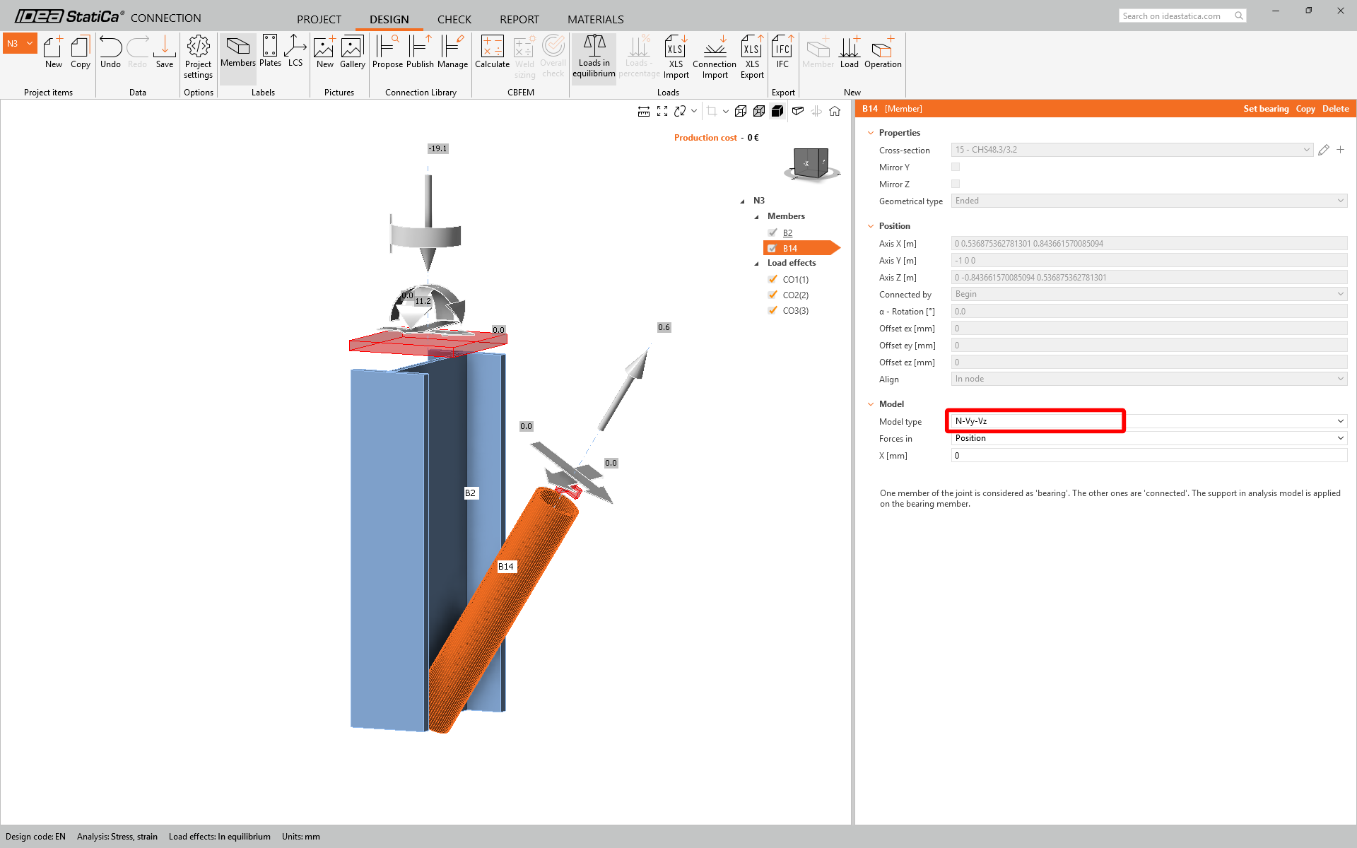
We are going to be using a single bolt connection for the diagonal brace. For this type of connection, we must also change the Model type of the brace member to N-Vy-Vz. Select the brace in the list of Members and modify the Model type in the drop-down list.
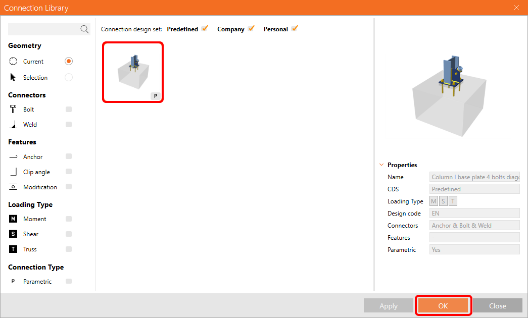
We are going to use the Connection Library to generate a connection. Select Propose and IDEA StatiCa will put forward possible solutions for the current geometry.

Connection Library shows you the possible solutions for the current geometry. Choose the template Column I base plate 4 bolts diagonal bolted weak and press OK.
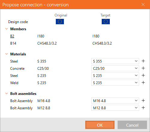
Accept the proposed values in the conversion tab and press OK.
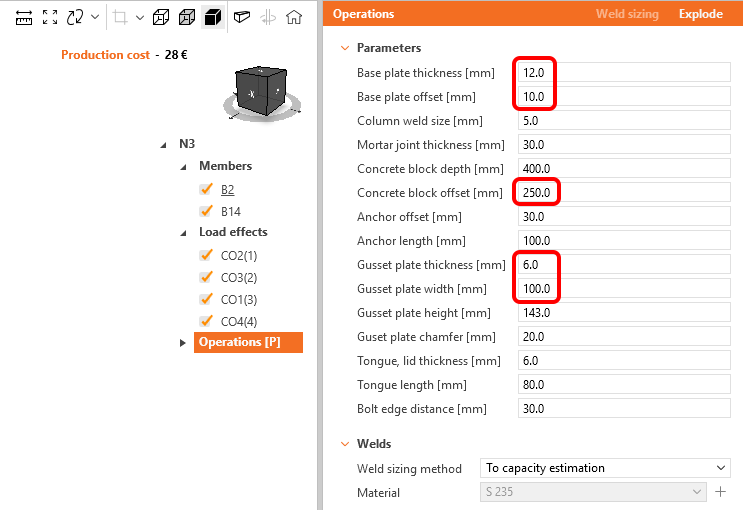
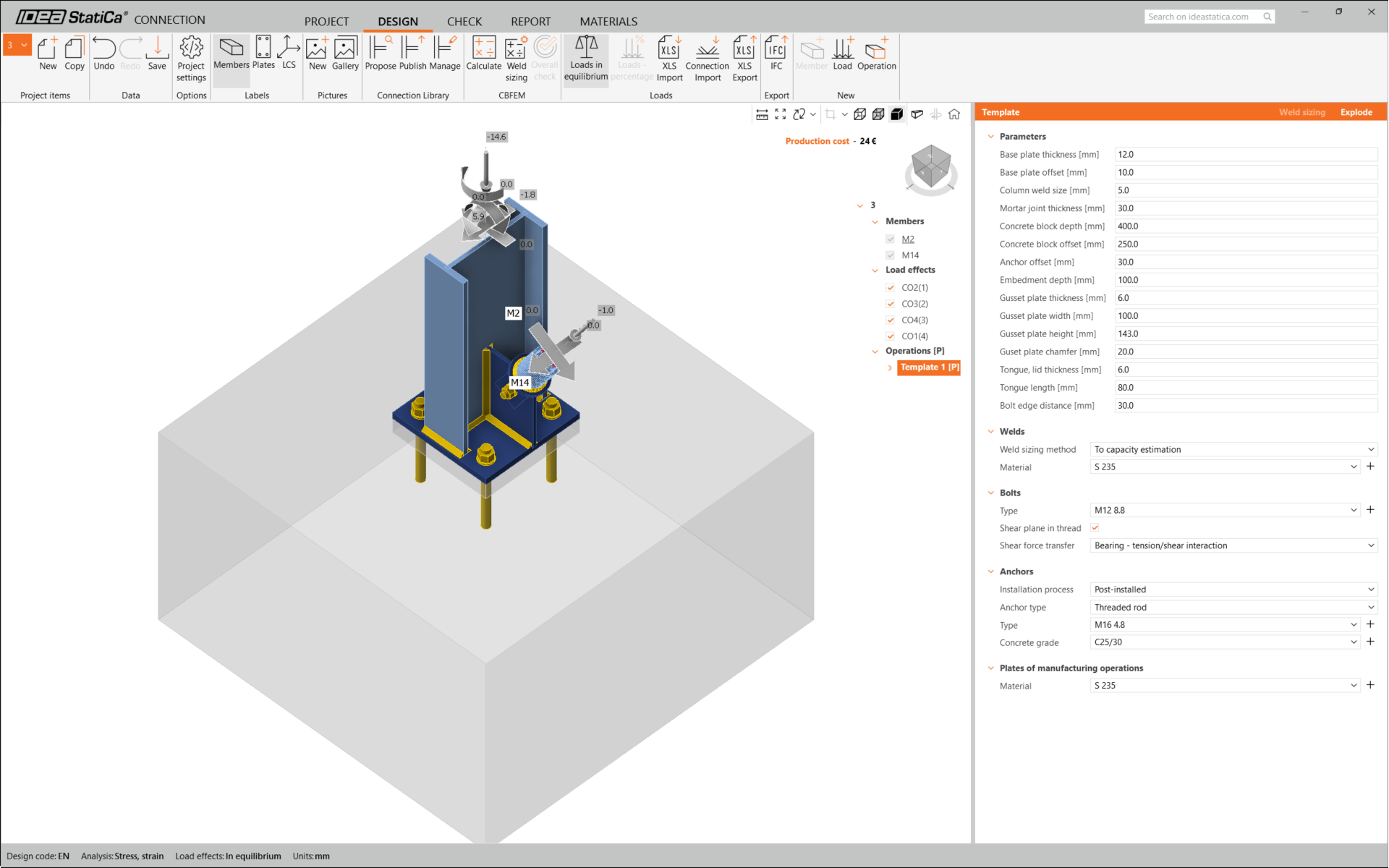
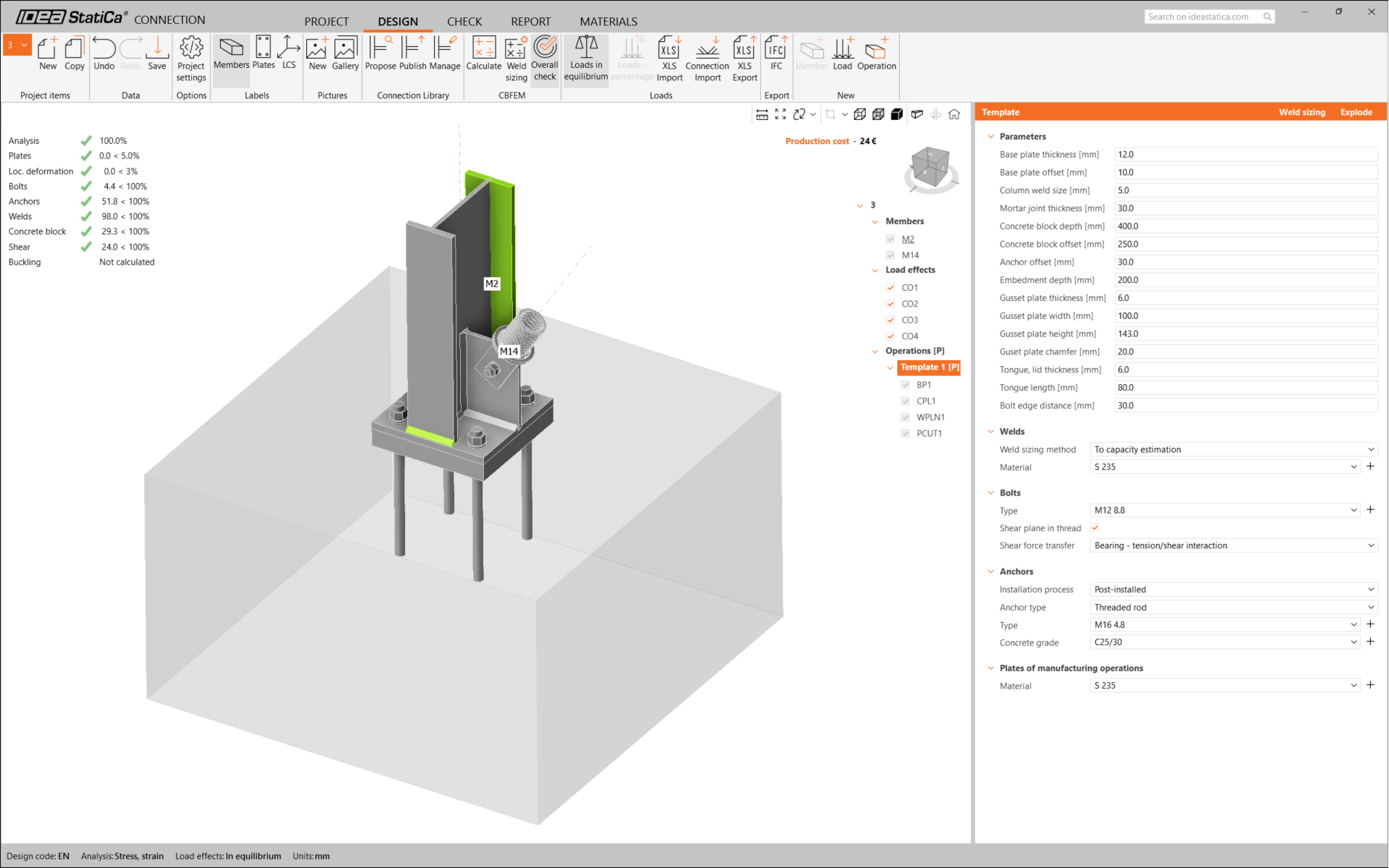
Edit the parameters of this template to fit the desired design – Base plate thickness to 12 mm, Base plate offset to 10 mm, Concrete block offset to 250 mm, Gusset plate thickness to 6 mm, and Gusset plate width to 100 mm.
This is what the initial connection looks like.
That completes the design of the connection for the column base plate with a diagonal brace.
Code-check and Report
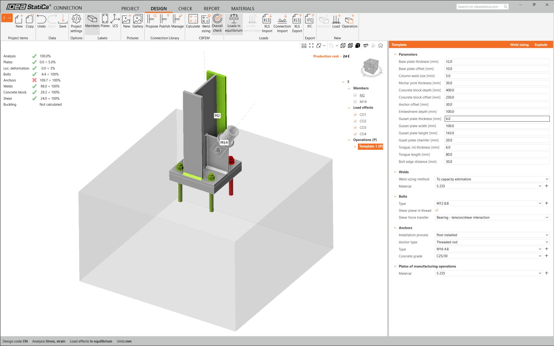
Now run a code-check using the Calculate icon in the CBFEM panel from the top ribbon.
Within IDEA StatiCa Connection, you can carry out many different types of analysis and code-checks. For more information, please see here.

The results might not be acceptable. In this case, the anchors fail because of their low design capacity.
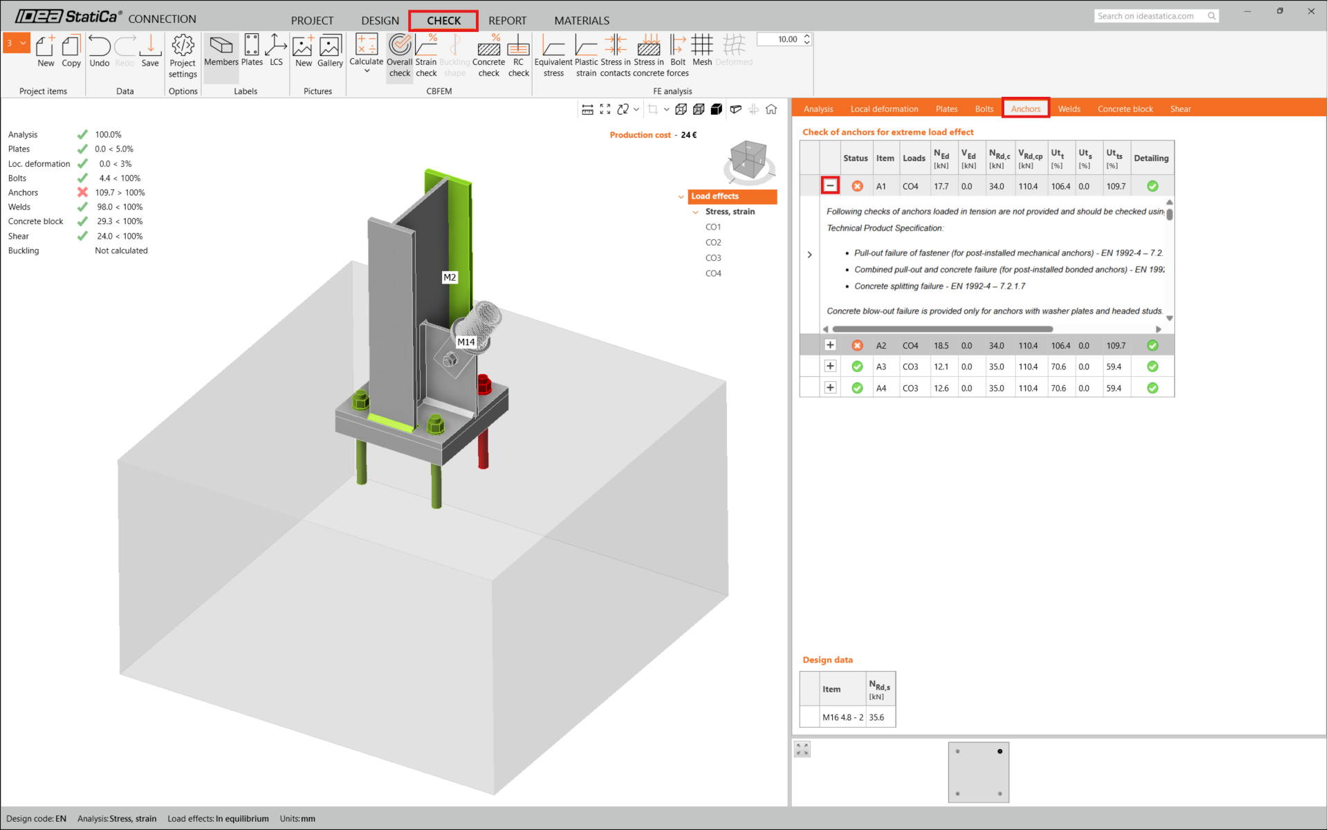
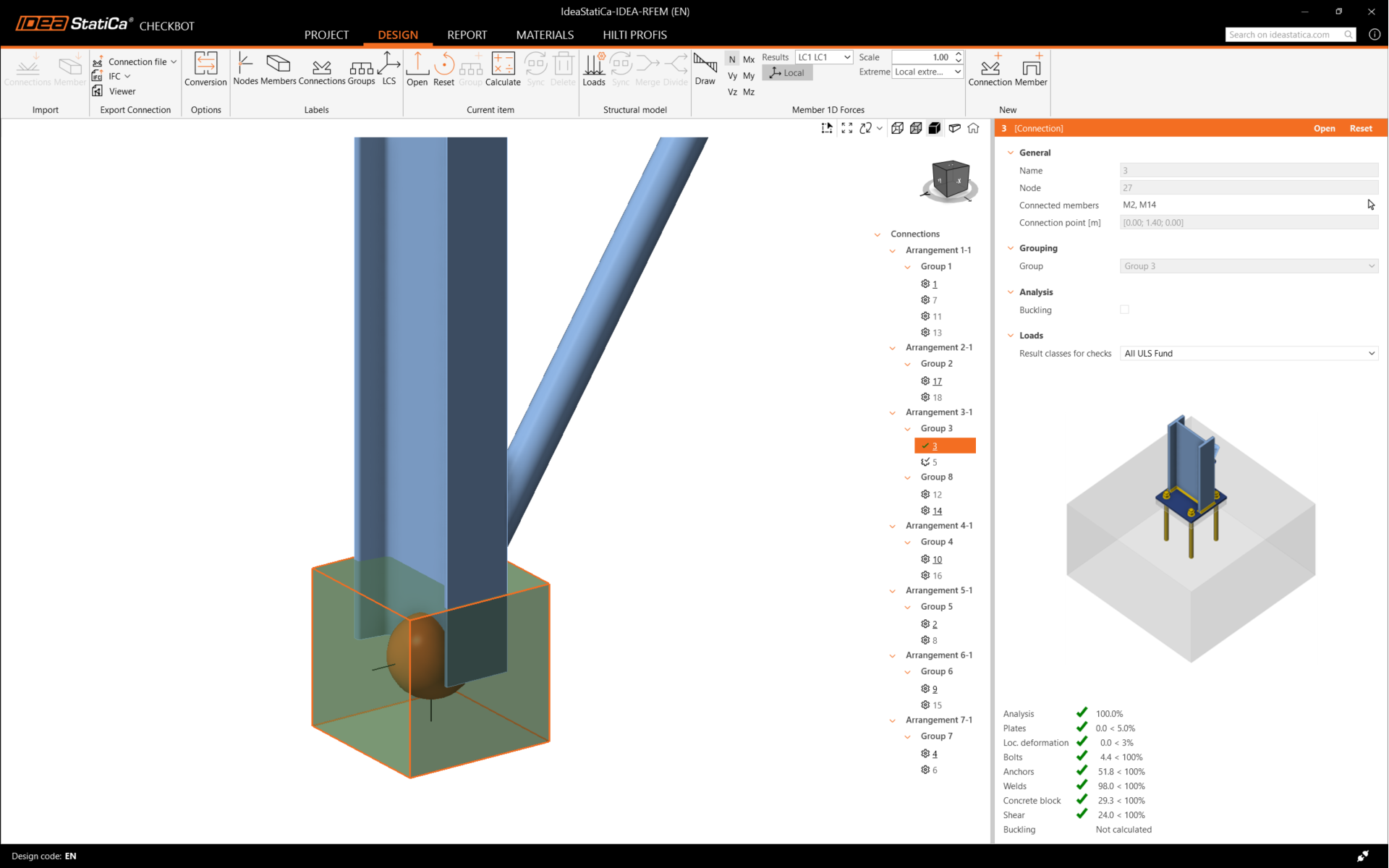
You can go to the Check tab to review the results and take a closer look at the anchors by expanding the calculation using the '+' symbol. You can see that the anchors are failing in tension in the concrete block.
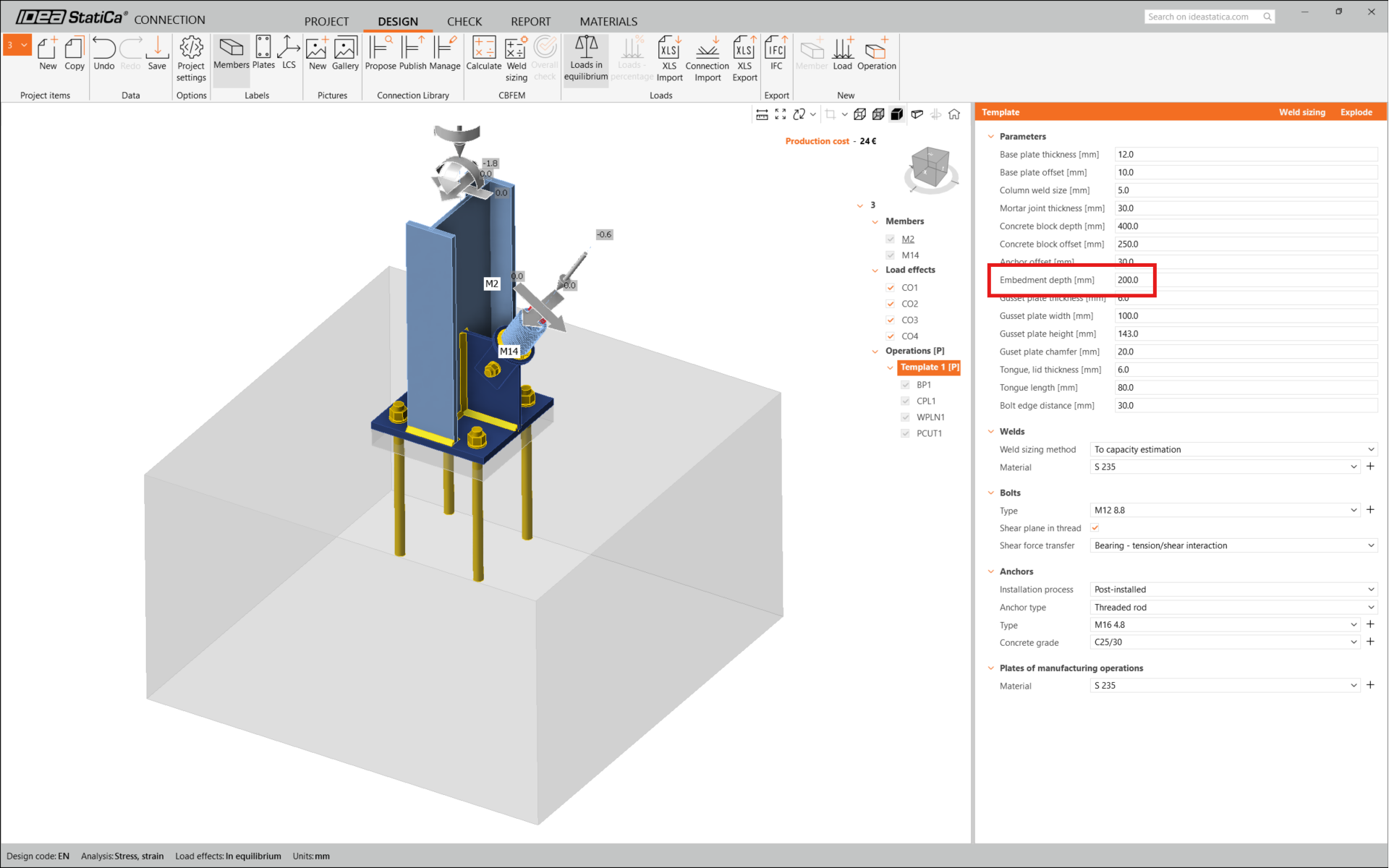
We must optimize the design to find the passing solution. Go back to the Design tab, click on the operation, and change the Anchoring length to 200 mm. Then run the analysis and code-check again.
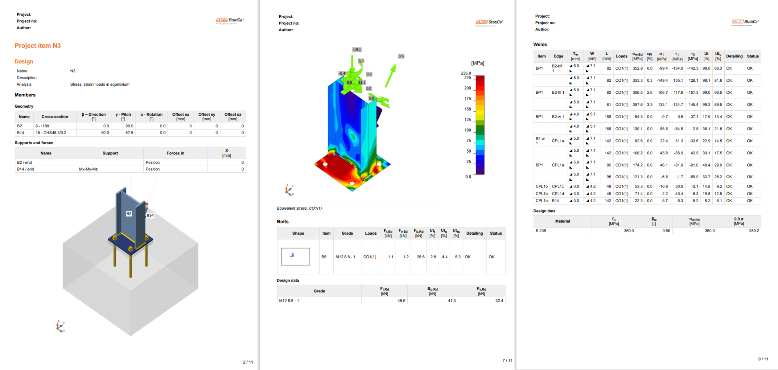
Once the code-check is finished in the Report tab, you can create the report containing results and diagrams for your connection model.
The report can be printed or saved in several formats. For more information, please see here.
Save this connection and switch back to the Checkbot window (you can keep the Connection window open).
In Checkbot, you will see a green tick next to the connection and the node box filled with green color. This means that the connection has passed all code-checks. In the Connection panel, you can also see a representation of the connection and a summary of the code-check results.
In the example below, you can see that only one connection has passed the respective code-check while the remaining connections have yet to be designed.
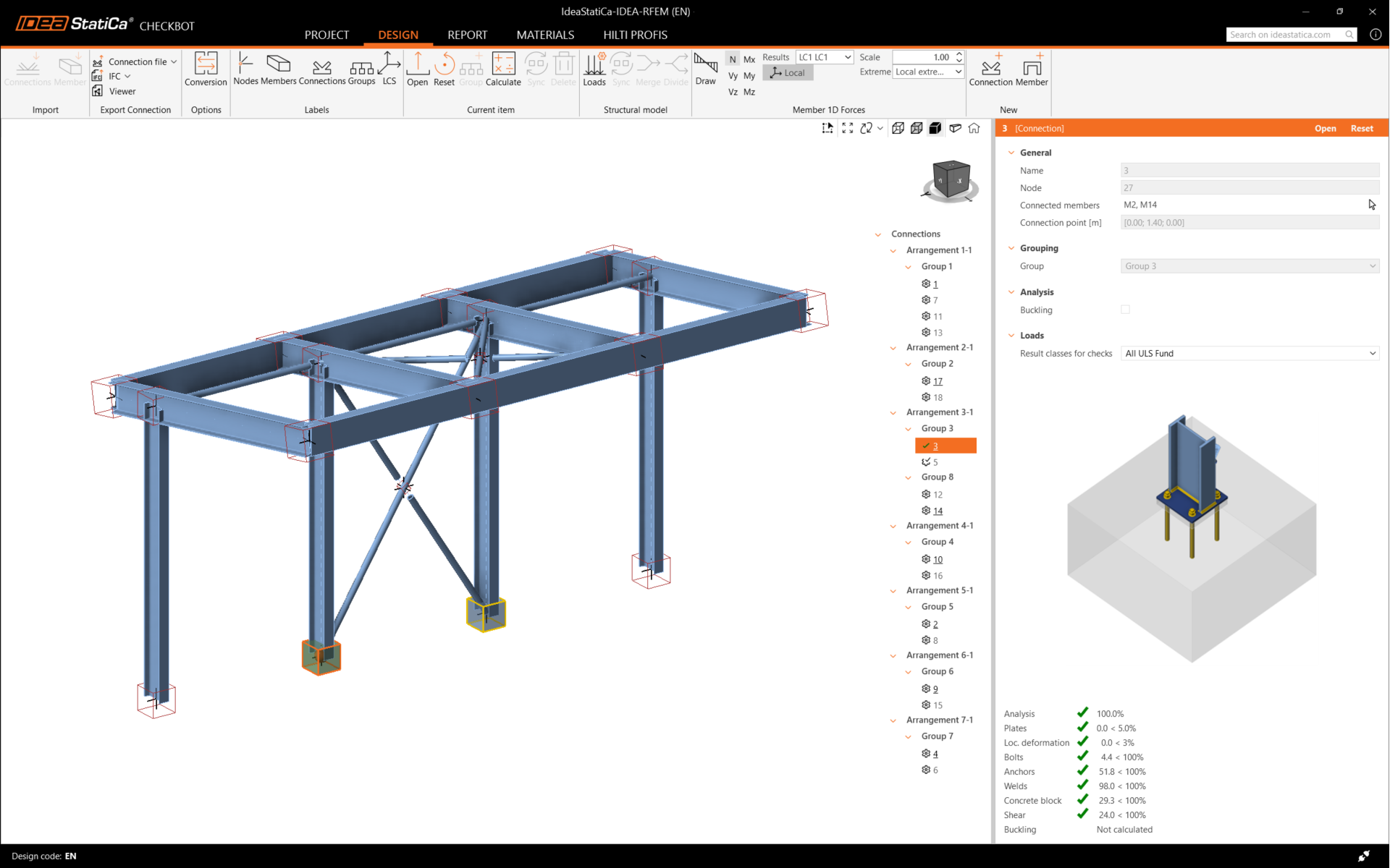
You can continue with the design of other connections, either one by one or using the bulk workflows.