
Key insights into constraints, member length and GMNA vs MNA analysis
MNA considers material nonlinearity, focusing on how materials behave under stress without accounting for changes in structure geometry. In contrast, GMNA incorporates both material nonlinearity and geometric imperfections, providing a more comprehensive analysis by considering deformations that alter the structure's geometry.
Selecting the appropriate analysis type depends on the specific constraints and member lengths. Properly setting these conditions ensures that the analysis aligns with the real-world performance of the structure. The constraints do not affect the bearing capacity and behavior of the connection for GMNA and MNA at all for symmetrical and axial-loaded connections but in the case of asymmetrical connection, the behavior is different. Asymmetrical connections generate discrepancies for axially loaded connections due to eccentricity, leading to considerable insecurity during the modelling process. The constraints are key and produce high divergence between the results for stress. The type of analysis and constraints significantly affect the behavior of the member/connection. For GMNA second-order effects are dependent on the length and connections on both sides of the member. The investigation of different behavior can be found in Chapter 03. MNA vs GMNA - Joint Design Resistance.
It is also important to keep the member length based on the default settings, which are based on decades of research and investigation. If the member is longer, failure can occur in different areas than in the vicinity of the connection due to the internal forces being far away from the node, leading to potentially different trends of forces. The proximity of the connection and the default length help minimize errors in the internal forces.
The article also focuses on asymmetrically assembled connections like gusset plates and their impact on secondary forces which should be verified with IDEA StatiCa Member. The constraints of the connected member to the joint in IDEA StatiCa Connection must correspond to the behavior of joints in IDEA StatiCa Member. The workflow of finding correct constraints is described in Chapter 07. Example: Asymmetrical gusset plate in IDEA StatiCa Member & Connection. Remember the IDEA StatiCa Connection addresses only local buckling instabilities. Global buckling is the governing factor and should be checked using global FEA or preferably in IDEA StatiCa Member, considering connection stiffness. The global imperfection should first be associated and analyzed in the global FEA, projected as the load or additional imperfection to the member model. Disregarding this imperfection can lead to underestimating the structural design.
01. MNA vs GMNA in general
Materially Nonlinear Analysis (MNA):
- Focus: Only consider the material nonlinearity of the structure.
- Material Nonlinearity: This refers to the nonlinear behavior of materials when they are subjected to loads beyond their elastic limit. In materials like steel or concrete, once the stress exceeds a certain threshold (yield strength), the relationship between stress and strain is no longer linear. This is called plasticity, and the structure may experience permanent deformation.
- Key Assumptions:
- The structure's geometry remains unchanged during the loading process (linear geometric behavior), and the deformations are calculated based on the original shape.
- The structure is analyzed for the changes in its material properties, but not for changes in shape or configuration.
Geometrically and Materially Nonlinear Analysis (GMNA):
- Focus: Considers both material nonlinearity and geometric nonlinearity.
- Material Nonlinearity: As in MNA, GMNA considers the material’s nonlinear stress-strain relationship beyond the elastic limit (plasticity, cracking, etc.).
- Geometric Nonlinearity: This refers to the changes in the geometry of the structure as it deforms. When a structure undergoes large deformations, its original geometry changes significantly, which affects the internal forces and stress distribution. The deformation itself influences how the structure behaves under load.
- Key Assumptions:
- Both the material properties and the geometry of the structure change as the load is applied.
- This is more accurate for structures with large deformations where the structure’s new shape under load must be accounted for, such as in slender columns or beams under buckling, or membranes like tensile fabric structures.
- In the absence of eccentricity, geometry remains undisturbed, necessitating the presence of initial imperfections.
Summary:
- MNA: Only material nonlinearities are considered (geometric effects are ignored).
- GMNA: Both material and geometric nonlinearities are considered (geometric changes due to large deformations are accounted for).
Thus, GMNA provides a more comprehensive analysis, especially for structures that undergo significant deformation or eccentrically assembled connections.
02. Model behind IDEA StatiCa Connection
Understanding the mechanical behavior of the model requires understanding how forces are transferred and how the model types for single members affect the connection behavior.
02.1. Numerical model
The construction of the numerical model ensures that it behaves as expected based on the internal forces in the nodes of each member. The ends of the members are secured by condensed elements that allow distortion and do not artificially stiffen the ends of each member. The coupling equations are incorporated into the ends of condensed elements and redistribute the loads from the individual members.
The length of the condensed element is taken as the 4 x maximum from CSS width and height.

\[\textsf{\textit{\footnotesize{01) Numerical model behind IDEA StatiCa Connection}}}\]
Model type N-Vy-Vz-Mx-My-Mz
The N-Vy-Vz-Mx-My-Mz model type is set up as the default for all models. The node with appropriate constraints is not bounded, and all six degrees of freedom are unrestricted, meaning that all forces can be applied. The various stiffness leads to distinct deformations of the member and the entire connection. The main takeaway should be:
- Six degrees of freedom are released in the node.
- All six internal forces can be applied.
- The stiffness of each part of the connected member defines the behavior of the connection.
- Keep member length as instructed by default settings.
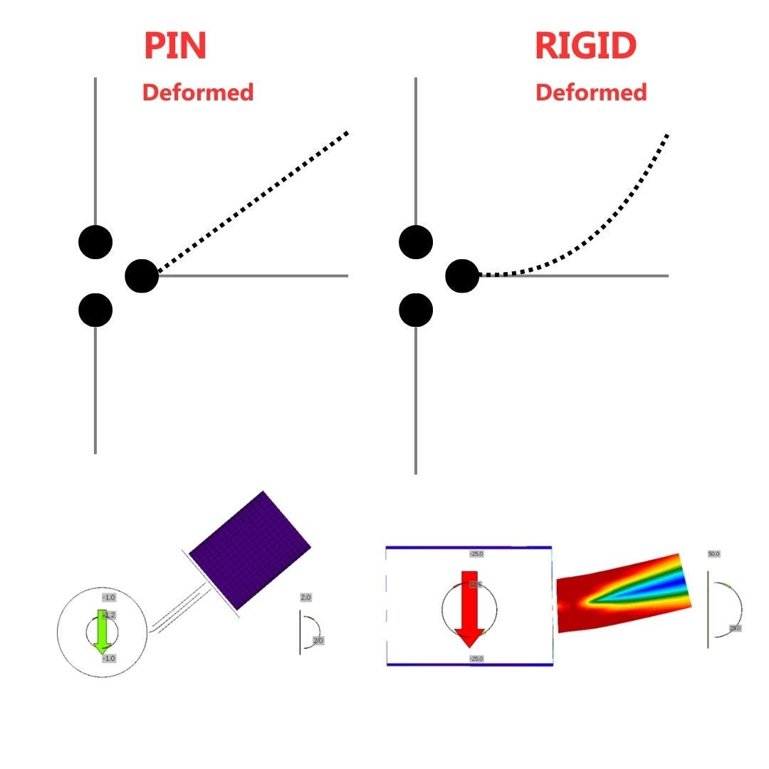
\[\textsf{\textit{\footnotesize{02) Analytical model behind IDEA StatiCa Connection for constraint in horizontal member N-Vy-Vy-Mx-My-Mz}}}\]
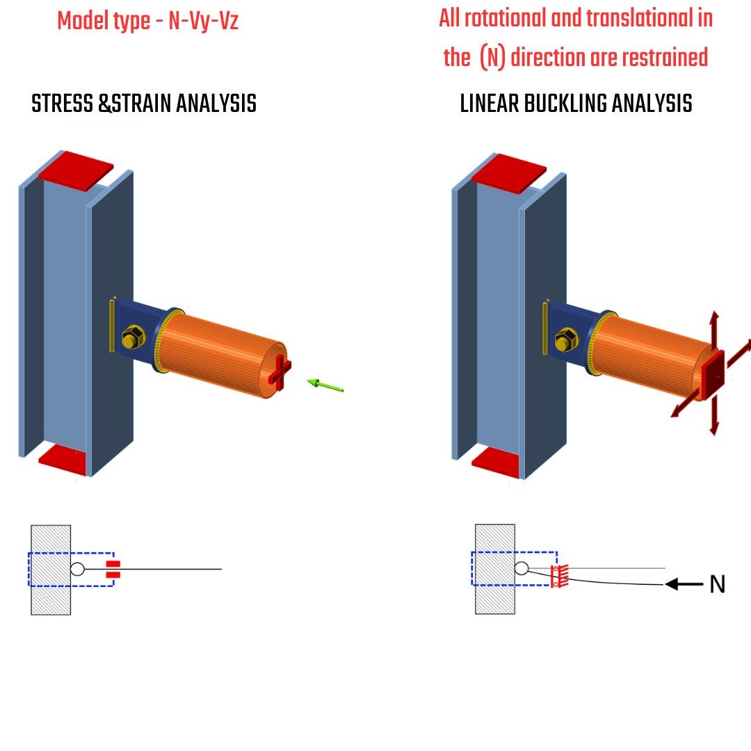
Model type N-Vy-Vz
The constraint N-Vy-Vz restrains the degrees of freedom in the node member where it is applied. All rotational degrees of freedom Rx-Ry-Rz are restricted, which influences the definition of internal forces as only N-Vy-Vz can be added to internal forces. These constraints alter the static scheme, leading to different deformations, additional reactions, stresses and nonconformities in the form of secondary reactions. The key points to remember are:
- Model type N-Vy-Vz should be utilized for stress-strain analysis in case one bolt connection to prevent kinematic rotational motion.
- Constraints produce moments in restrained degrees of freedom = additional stresses, secondary reactions .
- Do not use for eccentrically assembled connections = use IDEA StatiCa Member.
- The position of the shear load is irrelevant, because any bending moments are transferred via end supports.
- Keep in mind that the constraint is at the end of an invisible condensed element with the default length of 4 times the cross-section width or depth, whichever is larger.
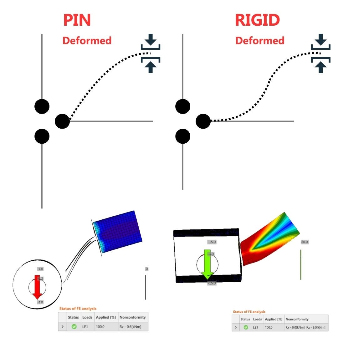
\[\textsf{\textit{\footnotesize{03) Analytical model behind IDEA StatiCa Connection for constraint in horizontal member N-Vy-Vz}}}\]
GMNA in IDEA StatiCa Connection
In the case hollow sections, especially with high diameter to thickness ratio, the geometrically linear analysis may not capture the behavior of the joint with sufficient precision, and its load resistance may be underestimated or overestimated. It is recommended to use more advanced geometrically and materially nonlinear analysis for joints of hollow sections. Therefore the GMNA analysis is activated whether the bearing member is a hollow section. Otherwise, the geometrical nonlinearity is disabled for the analysis of the whole connection model regardless of the settings in the code setup (GMNA on or off).
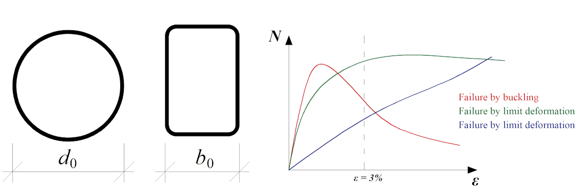
\[\textsf{\textit{\footnotesize{04) Sections supporting the GMNA}}}\]
Typical load-deformation diagrams for hollow section joints; the red curve is for thin-walled member loaded in compression, the green curve for regular members loaded in compression, the blue curve is e.g. for X-joint loaded by tension
03. MNA vs GMNA - Joint Design Resistance
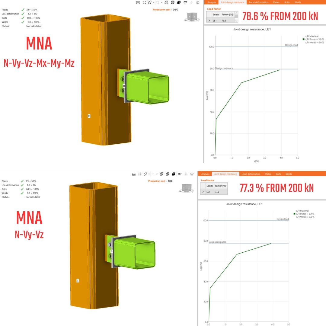
03.1. Symmetrical connection - N-Vy-Vz-My-Mx-Mz
Let's assume that most of the connections on the structures are assembled symmetrically. This implies that gusset plates are positioned on both sides, and bolts are evenly distributed, so the normal force does not cause any additional bending of the member. In this scenario, the distinctions between GMNA vs. MNA in IDEA Connection design will not generate big differences. The structural engineers do not permit large deformations on connections in most cases. It is attributed to the fact that geometrical nonlinearity does not induce additional stresses due to the deformation of the connection/structure element itself. This is also the goal of the 5% plastic strain limit for plate design, which is very close to elastic and small deformations assumptions.

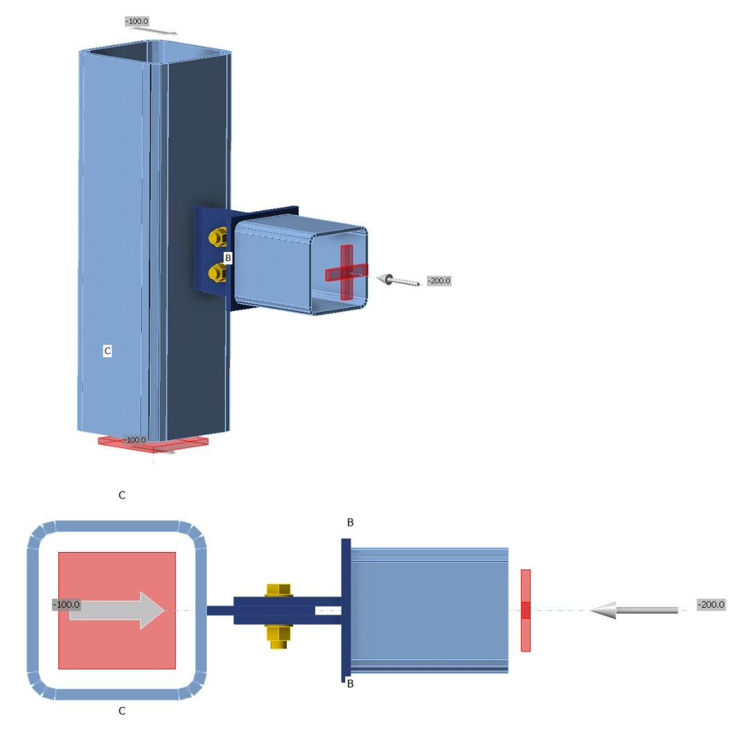
\[\textsf{\textit{\footnotesize{05) Symmetrical gusset plate and RHS section - only axial forces, model type N-Vy-Vz-Mx-My-Mz, equilibrium on }}}\]
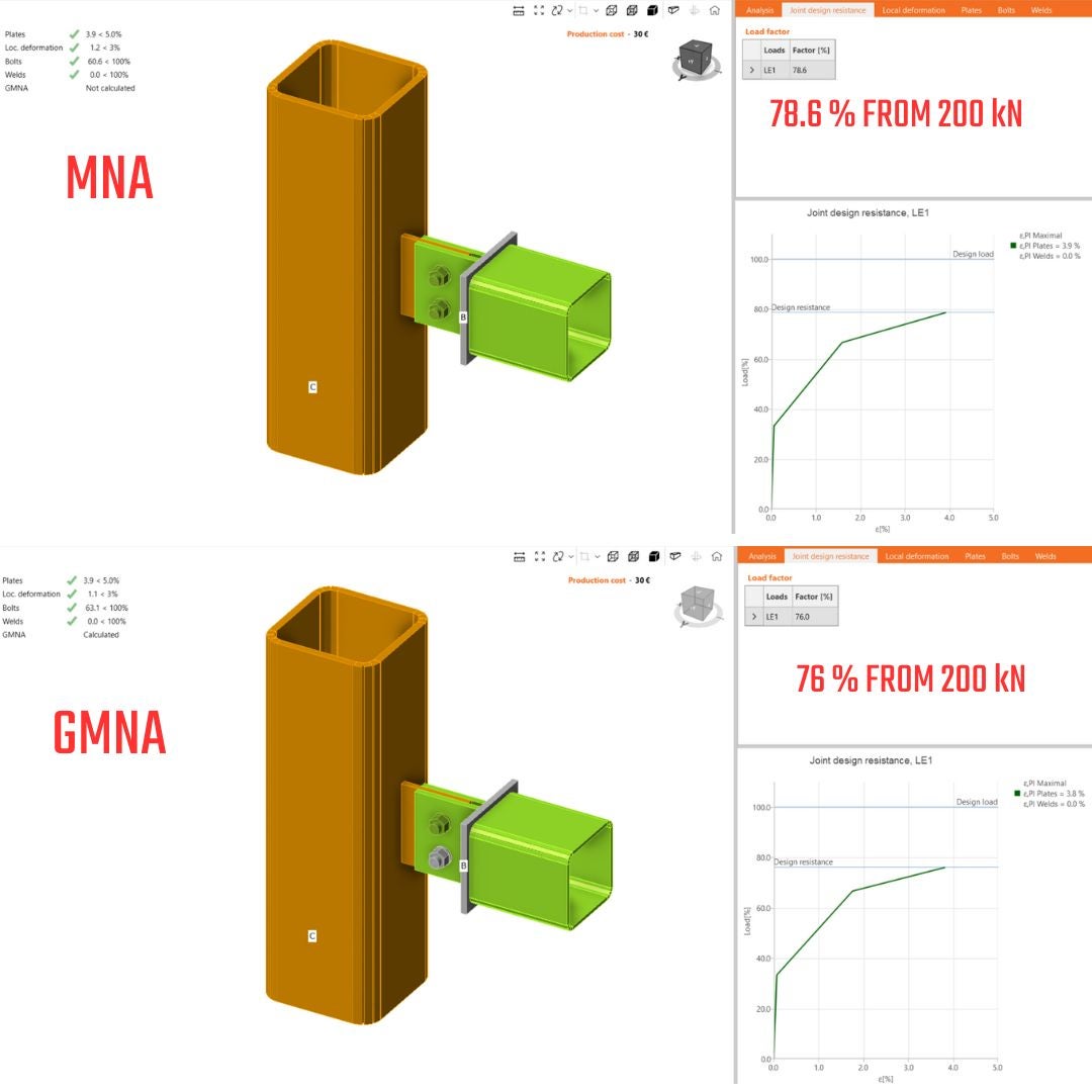
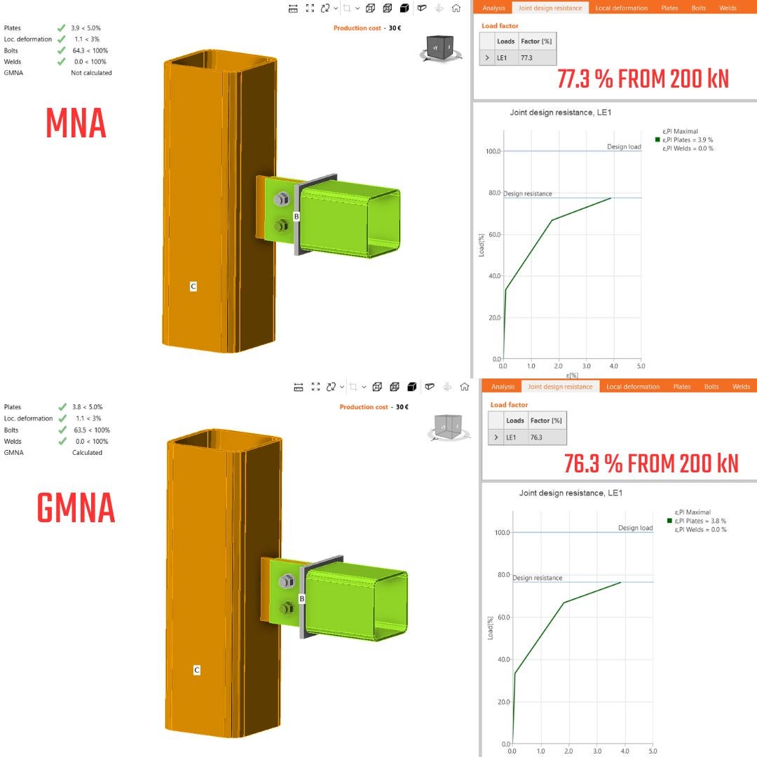
\[\textsf{\textit{\footnotesize{06) JDR analysis, differences between GMNA vs MNA}}}\]
The membrane stiffening effect induced by GMNA has been taken into consideration. This has resulted in a slightly lower capacity due to additional membrane stress, which has increased the stress state. The Von-Mises equivalent stress reached 5% plastic strain earlier. The difference is 2.6% in maximal force, which is not a significant discrepancy.
03.2. Symmetrical connection - N-Vy-Vz
The constraint N-Vy-Vz restricts the rotation (only allowing translations) in the node for the horizontal beam. Because of symmetry, very small moments close to zero will be induced in the support. I would conduct that for symmetrical constraints and axial force only; no changes in the results are expected.
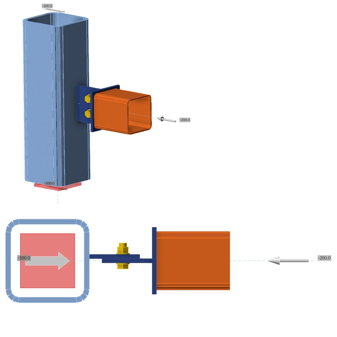
\[\textsf{\textit{\footnotesize{07) Model of symmetrically assembled gusset plate and RHS section - only axial forces included and, model type N-Vy-Vz, equilibrium on}}}\]
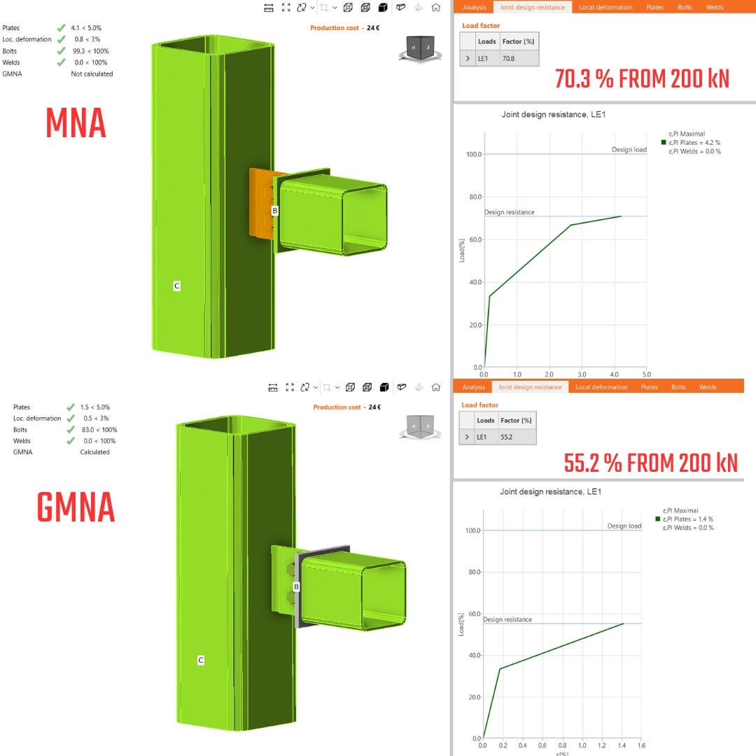
\[\textsf{\textit{\footnotesize{8) JDR analysis, differences between GMNA vs MNA}}}\]
03.3. Asymmetrical connection - N-Vy-Vz-My-Mx-Mz
Due to eccentricity, asymmetrically designed connections are prone to additional bending moments and second-order effects. Those types of connections are generally tricky to design. In the following example, differences in the results are demonstrated:

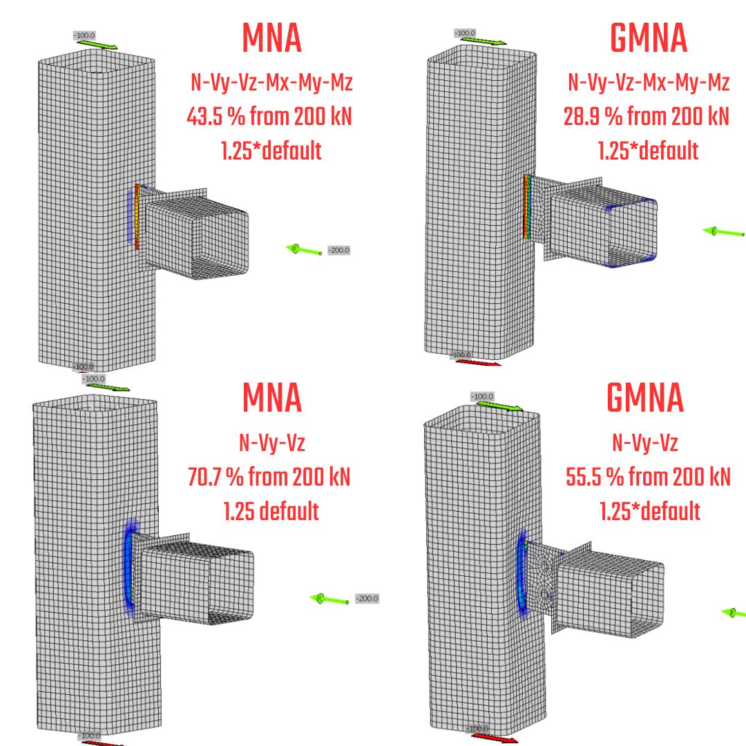
\[\textsf{\textit{\footnotesize{09) Asymmetrical gusset plate and RHS section - only axial forces, model type N-Vy-Vz-Mx-My-Mz, equilibrium on}}}\]

\[\textsf{\textit{\footnotesize{10) JDR analysis, differences between GMNA vs MNA}}}\]
The disparities in bearing capacity are significant. This is because in GMNA, a new deformed connection geometry is created with each increment of loading, leading to additional bending stress. For the MNA, the load increments are built up on the undeformed model, preventing these additional stresses. This means that eccentric connections are susceptible to second-order effects driven by the connection's stiffness. The contrasts in capacity for the presented models are 33%, but this value could be even higher for different gusset plate setups.
03.4. Asymmetrical connection - N-Vy-Vz
The rotational constraint in the node of a horizontal beam prevents deformation and leads to increased moments in the support (secondary reactions). Due to these constraints, there are significant differences in the bearing capacity of the connection itself. When comparing the bearing capacity under constraints N-Vy-Vz-Mx-My-Mz and constraints N-Vy-Vz, there is a 26.8% discrepancy. The model with N-Vy-Vz constraints exhibits higher bearing resistance. Similar discrepancies are also observed for GMNA.
\[\textsf{\textit{\footnotesize{11) Asymmetrical gusset plate and RHS section - only axial forces, model type N-Vy-Vz, equilibrium on }}}\]
\[\textsf{\textit{\footnotesize{12) JDR analysis, differences between GMNA vs MNA}}}\]
03.5. The conclusion from GMNA vs MNA - Joint Design Resistance
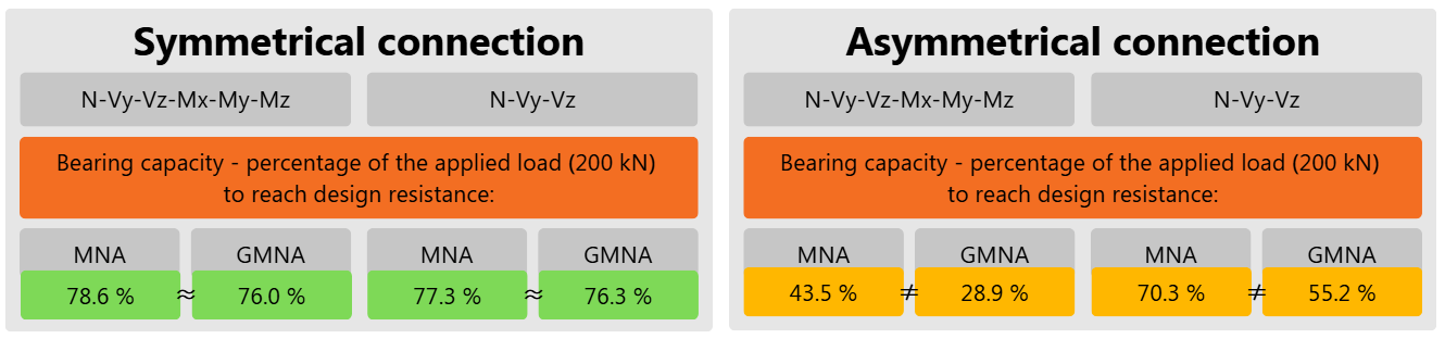
\[\textsf{\textit{\footnotesize{13) Summary of results from stress-strain analysis for default length of the members}}}\]
Based only on the bearing capacity with default settings in IDEA StatiCa app can be summarized:
- The constraints do not affect the bearing capacity and behavior of the connection for GMNA and MNA at all for symmetrical and axial-loaded connections.
- If shear forces are applied to symmetrical connections, the constraints matter, leading to differences in results between GMNA and MNA due to secondary forces.
- Asymmetrical connections generate discrepancies for axially loaded connections due to eccentricity, leading to considerable insecurity during the modelling process. The constraints are key and produce high divergence between the results for stress.
- The first recommendation for eccentrically assembled connections -> run an MNA analysis and use the instructions in this article.
- For GMNA, second-order effects are dependent on the length and connections on both sides of the member. This configuration cannot be utilized in connection design as it leads to significant insecurities. The second recommendation we push is to use IDEA StatiCa Member to know the appropriate behavior of connections and members.
- Use GMNA only for punching or local effect on the RHS, SHS, or tube section to detect the membrane stiffening effect.
04. Impact of Member Length on Results
The member length comes from decades of research and investigation. The connections are local regions on the structure, and at IDEA StatiCa Connection, we endeavor to understand the behavior in the vicinity of the connection instead of the entire length of the beams where the global FEA tools play the leading role.
04.1. Symmetrical gusset plate connection - axial load only
The axial load and MNA analysis are used to determine the response of structures. As mentioned above, GMNA will not alter the response for symmetrically assembled connections. The comparison between a default length of 1.25 times the length of the related members and 10 times the length of the related members with various constraints is recapitulated below.
\[\textsf{\textit{\footnotesize{14) JDR analysis, MNA, default length of the member and axial load only}}}\]
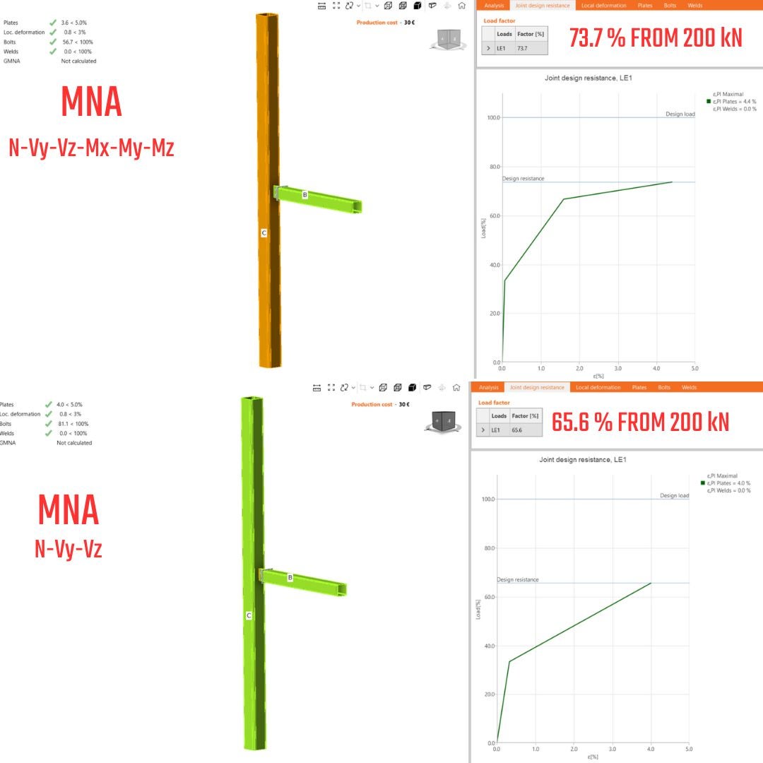
\[\textsf{\textit{\footnotesize{15) JDR analysis, MNA, 10*height of the member and axial load only}}}\]
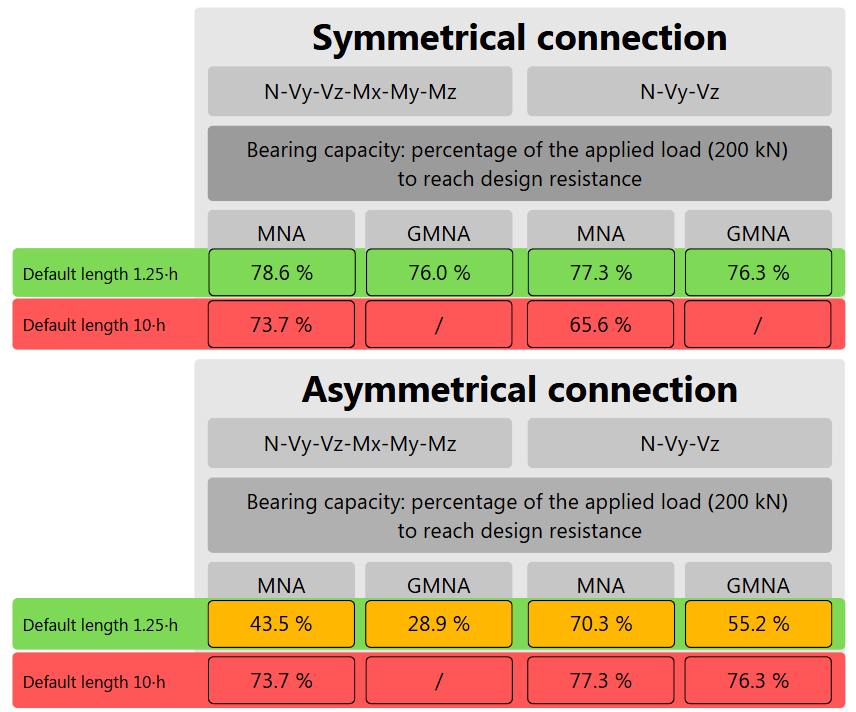
04.2. The conclusion from GMNA vs MNA - Joint Design Resistance - nonstandard length
Based only on the bearing capacity with a nonstandard length of related members in the IDEA StatiCa app can be summarized:
\[\textsf{\textit{\footnotesize{16) Summary of results from stress-strain analysis for a nonstandard length of the members}}}\]
- For symmetrically designed connections subjected to axial loading, the type of analysis, length, and constraints have minimal impact on the bearing capacity.
- Differences are up to 10 %. A higher portion of the discrepancy is caused by N-Vy-Vz constraints (only for the axial load and this connection). The discrepancy is caused by a different failure location.
- If the member is longer, failure can occur in different areas than in the vicinity of the connection due to the internal forces being far away from the node, leading to potentially different trends of forces. The proximity of the connection and the default length help minimize errors in the internal forces.
- Keep the member length based on the default settings.
04.3. How to handle asymmetrical gusset plate connection with axial load only?
The advice mentioned above is crucial for simulating and designing asymmetrically assembled connections. The type of analysis and constraints significantly affect the behavior of the member/connection. The question then arises: which analysis and constraints should be used? Surprisingly, none of those solutions are available in IDEA StatiCa Connection. Instead, using IDEA StatiCa Member to simulate the appropriate behavior of the member and connections is the way. The constraints and analysis type in IDEA StatiCa Connection cannot predict a precise solution because information about the second connection and member length is missing. This leads to an unclear statement for connection design. As seen in the case with GMNA and constraint N-Vy-Vz-Mx-My-Mz (Fig.17), the bearing capacity is lowest due to second-order effects. If you increase the member length, the stiffness drops rapidly, as clearly shown in Figure 18. For GMNA and 10 times the default length, the bearing capacity reached only 5.9%.
\[\textsf{\textit{\footnotesize{17) JDR analysis, 1.25*default length of member, N-Vy-Vz-Mx-My-Mz}}}\]
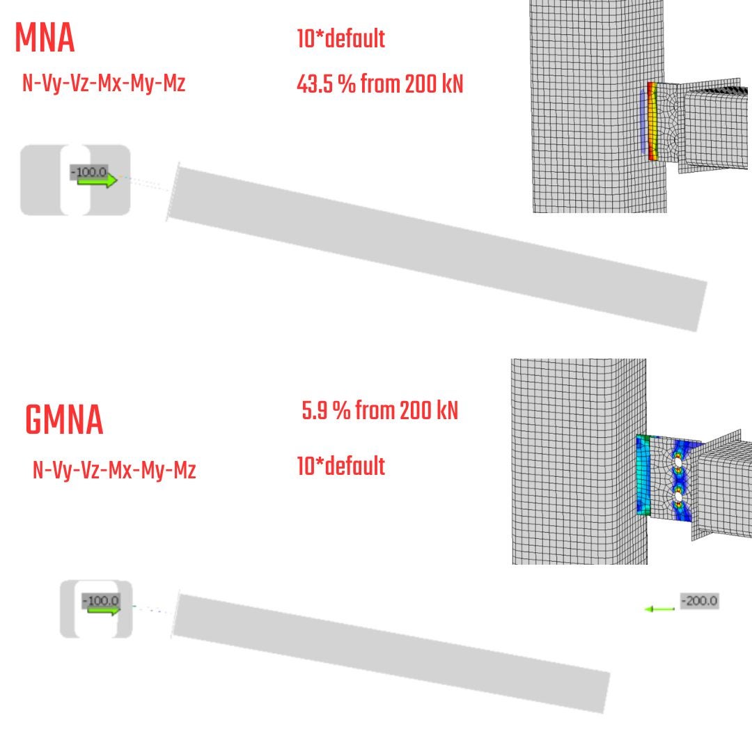
\[\textsf{\textit{\footnotesize{18) JDR analysis, 10*default length of member, N-Vy-Vz-Mx-My-Mz}}}\]
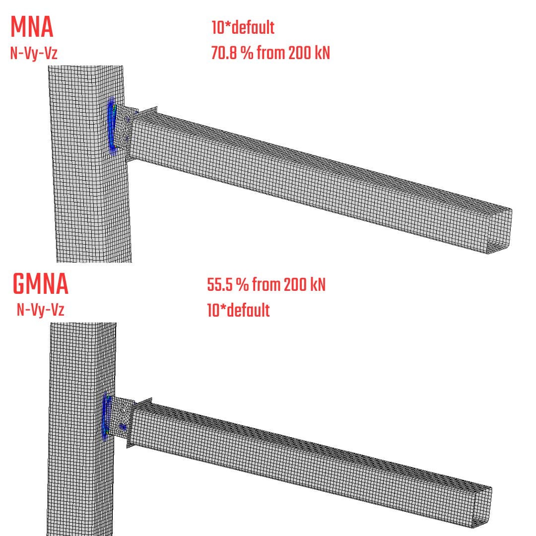
\[\textsf{\textit{\footnotesize{19) JDR analysis, 10*default length of member, N-Vy-Vz}}}\]
- Retain the member length as default - settings coming from research and decades of investigation
- More extended members = increasing error on the side of internal forces redistribution
- More extended members = different failure area than in the vicinity of connections, you solve a local problem, not a global one
- Due to two unknowns (real member length, and connection on the other side), the second-order effect is hanging on the length = Increasing length leads to lower bearing capacity. The connection on the other side of the analyzed member drives the bearing capacity due to stiffness that is unknown for the IDEA StatiCa Connection.
- For asymmetrically assembled connections use IDEA StatiCa Member
05. Nonconformity - secondary forces
The nonconformities identified after analysis provide additional general information about the model. Secondary forces results from rotational restrains at the node.
\[\textsf{\textit{\footnotesize{20) Nonconformity, secondary forces, one bolt connections}}}\]
- The N-Vy-Vz model type restrains the rotations - secondary forces will appear.
- The secondary forces vary the stress state of related member.
- The impact of secondary forces should be verified with IDEA StatiCa Member to be confident that you are in a reasonable stress state range.
06. Conclusion and advice for connection design
06.1. Symmetrically assembled connections
- Connections are not prone to significant oscillations in the bearing capacity and lead to safe and economical design.
- The length of the member does not affect the bearing capacity of the connection itself. However, when the member length is altered, it can lead to unrealistic forces and earlier failure, but in a different location than the proximity of the connection. Therefore, it is recommended to keep the member length at its default setting.
06.2. Asymmetrically assembled connections
- Default settings of member length
- GMNA affects the results and in comparison with MNA (for this case setup and default length) brings up to 33 % lower bearing capacity due to geometrical nonlinearity.
- The constraints impact the results enormously. Higher bearing capacity appears for N-Vy-Vz restraints due to rotational restriction and lower effect of deformation. The constraints matter.
- Nonstandard member length - 10*h
- The MNA analysis indicates the same bearing capacity as the default settings for member length.
- GMNA, compared with MNA, indicates 15 % differences for N-Vy-Vz constraints but 38 % for N-Vy-Vz-Mx-My-Mz. The differences are caused by the member's different bending stiffness because of length and disinformation about the second connection at the end of the member that will drive the deformation.
06.3. Recommendations for Connection Design
- Preserve the member length as the default.
- Symmetrically assembled connections are independent of the analysis type, member length, and constraints for axially subjected gusset plates.
- For asymmetrically designed gusset plates utilize:
- IDEA StatiCa Member.
- The IDEA StatiCa has limitations and eccentrically subjected gusset plates are one of those that need supplementary information like the length of the member and connection at the end of the member to reach the correct design procedure.
07. Example: Asymmetrical gusset plate in IDEA StatiCa Member & Connection
The associated section's objective regarding the leverage provided by the member application is to identify discrepancies and critical areas when utilizing the structures' submodel. This section contains essential information, such as the length of the member and the configuration of the secondary connection located on the opposing side of the critical member.
07.1. Model in IDEA StatiCa Member
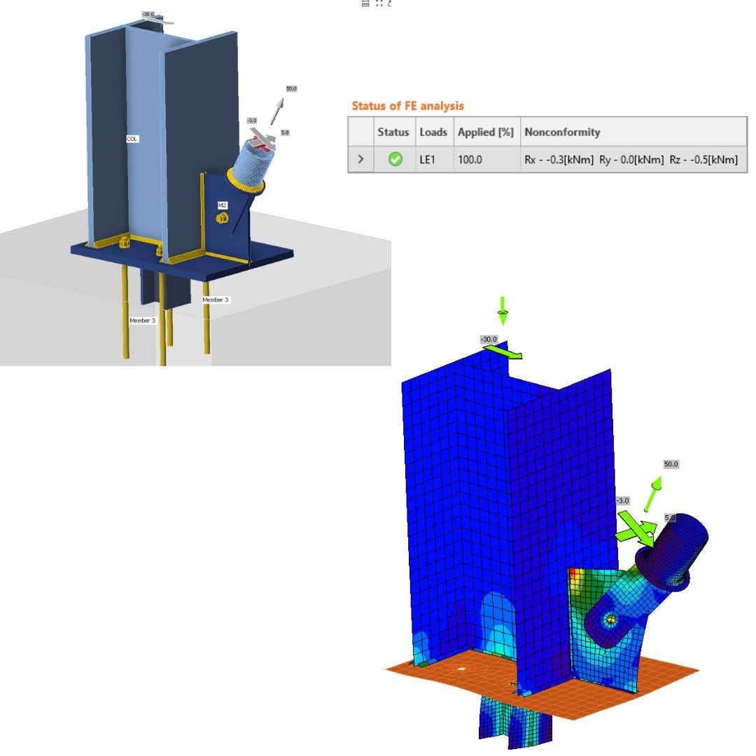
The horizontal distance between the columns is designed to be 6 meters. This design features asymmetrically assembled gusset plates at both ends of the horizontal member. The columns have fixed boundary conditions at both the top and bottom parts of the associated members. While all degrees of freedom are restricted, horizontal translation is permitted on the column where the force is applied.

\[\textsf{\textit{\footnotesize{21) Member model, constraints, loads}}}\]
A maximum force of 110 kN can be transferred through the system comprising horizontal and vertical members. If this force is exceeded, the system will become unstable, necessitating a post-critical behavior analysis. This is not the intended focus of the structural engineers. The bearing capacity for MNA (Material Nonlinear Analysis) and GMNA (Geometric Material Nonlinear Analysis) is adequate, reaching a maximum value of 1.1% equivalent plastic strain. This indicates a lower bound horizon of 5%, which aligns with the code limit strain for the ultimate limit state. As you can observe, the critical buckling factor achieved a value of 5.67 for global buckling, and the shape emulates the sinusoidal shape due to the small stiffness of the plates in the transversal direction (out of plane). The second mode shape is orthogonal to the first one and also evokes a global buckling instability shape. The third shape represents local plate buckling, which should be reachable in the IDEA StatiCa Connection.
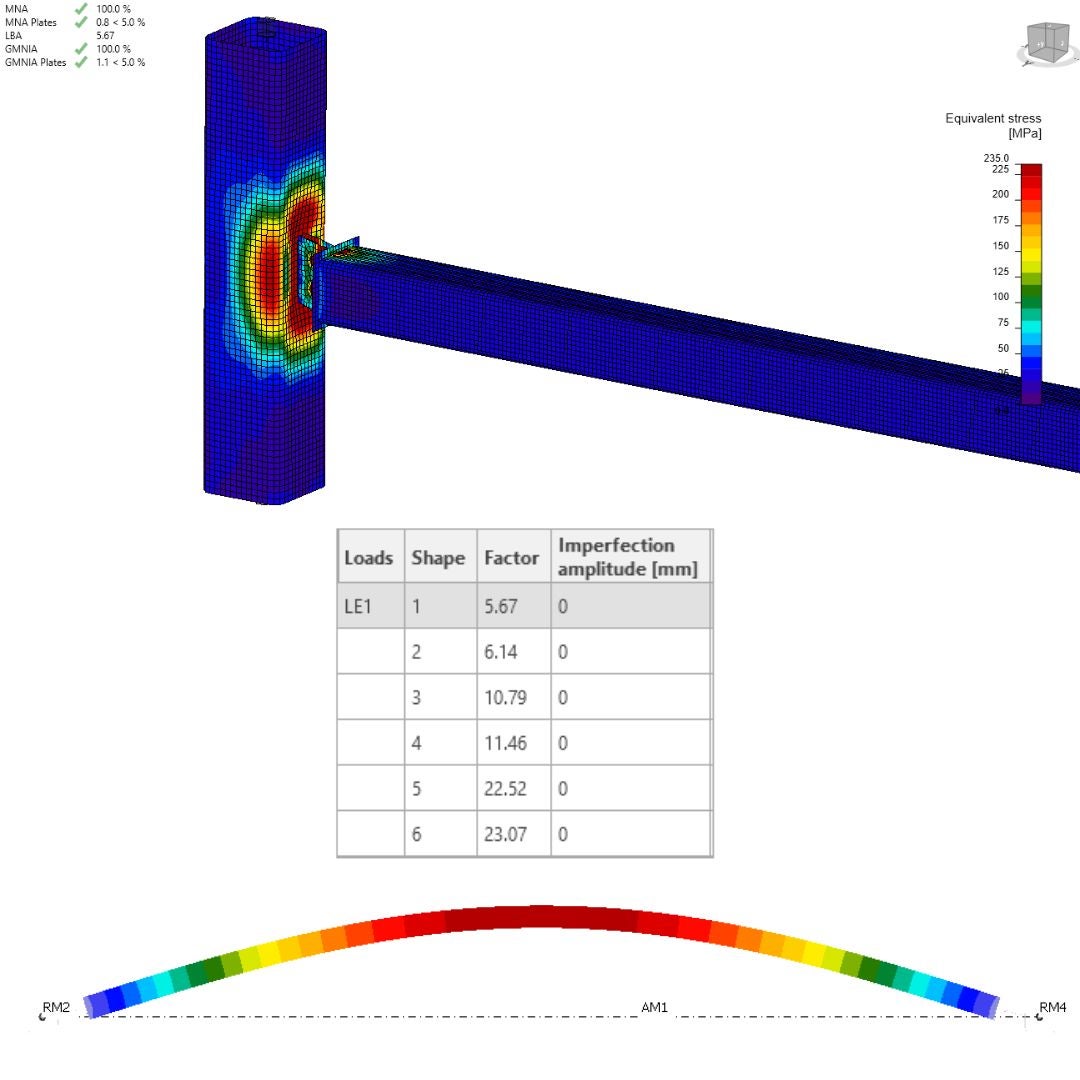
\[\textsf{\textit{\footnotesize{22) Results, Equivalent Stress, Linear Buckling - first mode shape (global buckling)}}}\]
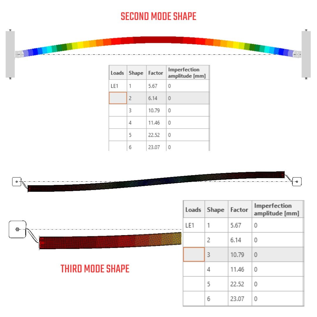
\[\textsf{\textit{\footnotesize{23)Linear Buckling - second mode shape (global buckling), third mode shape (local plate buckling)}}}\]
See How IDEA StatiCa Member works.
07.2. Asymmetrical Gusset plate: MNA vs. GMNA - N-Vy-Vz-Mx-My-Mz
Stress&Strain in IDEA StatiCa Connection - MNA
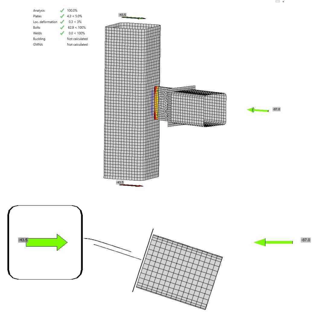
The comparison between MNA in IDEA StatiCa Connection and IDEA StatiCa Member reveals essential differences. The model type N-Vy-Vz-Mx-My-Mz can transmit all six internal forces. The maximum normal force that can be applied to the horizontal member in IDEA StatiCa Connection, and the corresponding bearing capacity, is 87 kN under compression. This results in a 4.3% plastic strain, leading to a failure mode in the welded plate of the column due to a combination of bending and axial stresses. The observed deformed shape indicates that the horizontal member functions as a cantilever with a free end. This deformation does not conform to the shape produced by the IDEA StatiCa Member. The model type N-Vy-Vz-Mx-My-Mz does not adequately represent the action of the eccentric connection in the structure because only the free end is modeled, and the support of the element at its other end is missing. This action can be simulated using the model type N-Vy-Vz. The residual forces are generated due to the shift and spin of the connection center, which can cause a bias in the forces.
\[\textsf{\textit{\footnotesize{24) Plastic strain, failure mode, deformation}}}\]
Stress&Strain in IDEA StatiCa Connection - GMNA
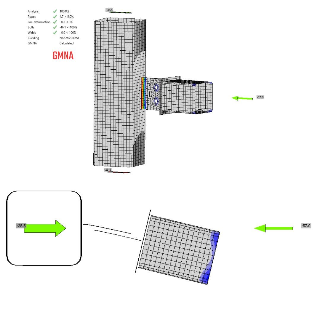
The GMNA is suitable for SHS and RHS sections because of the local punching and membrane stiffening effects on these profiles. By applying this advanced analysis, you also obtain the second-order moment, which increases the stress state on the critical plate. This results in a significantly lower load level that can be applied before failure occurs. The solution provides the same relative deformation as the MNA. The model can only support an axial load of 57 kN on the horizontal member before reaching failure mode, which represents a reduction of about 35% in bearing capacity as opposed to MNA. Additionally, the model type N-Vy-Vz-Mx-My-Mz is inappropriate for this analysis, as it deepens the errors caused by the misuse of the model type.
\[\textsf{\textit{\footnotesize{25) Plastic strain, failure mode, deformation}}}\]
Stress&Strain in IDEA StatiCa Member
The model in IDEA StatiCa Member has successfully transferred an axial load of 110 kN, prior stability issue, in the horizontal member. The capacity of the member to sustain this higher load can be attributed to the characteristics of the submodel, which possesses an understanding of the connection configuration on the opposing side as well as the length of the member. This awareness facilitates variations in deformation and redistribution of stresses. In this context, the member operates as a hinged member within IDEA StatiCa Member, whereas it functions as a cantilevered member in IDEA StatiCa Connection. It conducts to the conclusion that model type N-Vy-Vz-Mx-My-Mz is not appropriate for eccentric gusset plate.
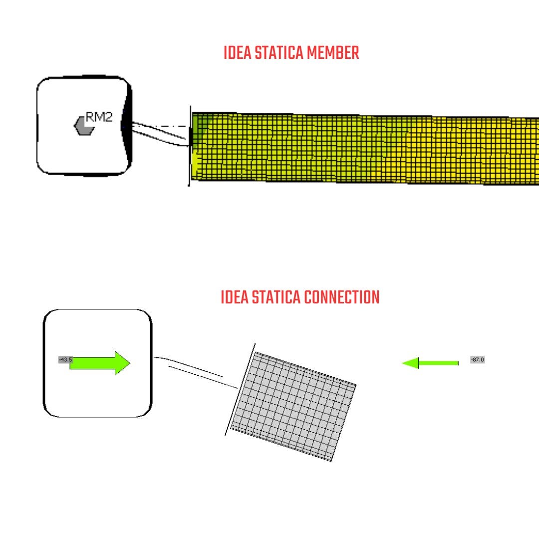
\[\textsf{\textit{\footnotesize{26) Deformed shape comparison between the Member and Connection model}}}\]
07.3. Asymmetrical Gusset plate: MNA vs. GMNA - N-Vy-Vz
Stress&Strain in IDEA StatiCa Connection - MNA
The model type has altered the bearing capacity of the connection, allowing it to transfer 140 kN before losing structural integrity and reaching a 5% plastic strain. There is a significant difference when comparing the results of the MNA model with the N-Vy-Vz model type vs. those of the N-Vy-Vz-Mx-My-Mz. The force increase for the N-Vy-Vz model type is approximately 39% compared to the N-Vy-Vz-Mx-My-Mz model type. Additionally, it is worth mentioning that secondary forces from the N-Vy-Vz model type have been identified, which introduce extra stresses into the model due to restrained rotations.
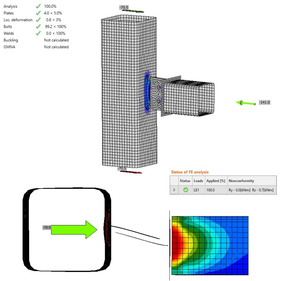
\[\textsf{\textit{\footnotesize{27) Plastic strain, failure mode, deformation -MNA}}}\]
Stress&Strain in IDEA StatiCa Connection - GMNA
The GMNA resulted in a reduction of bearing capacity compared to MNA, with a significant drop when comparing the GMNA for the N-Vy-Vz-Mx-My-Mz model type. This difference is due to varying constraints, as the N-Vy-Vz constraints provide approximately 49% higher bearing capacity than N-Vy-Vz-Mx-My-Mz. Additionally, the rotation has introduced a bending moment in the 'Y' direction, which means that extra rotation will occur within the model and lead to additional artificial stress compared to the IDEA StatiCa Member model. This is because of the condensed element length and the model type assigned to a position that restricts free rotation.
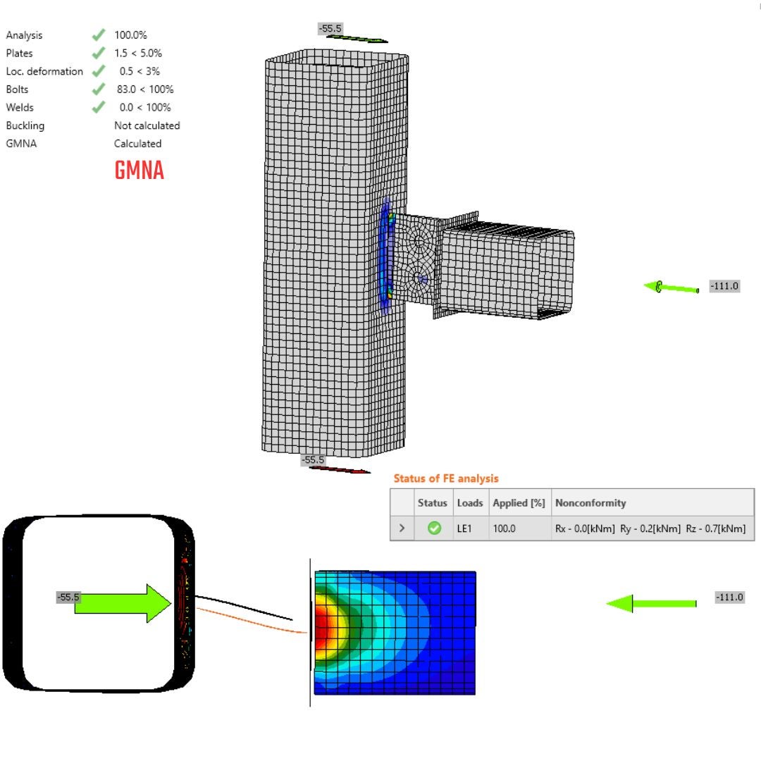
\[\textsf{\textit{\footnotesize{28) Plastic strain, failure mode, deformation -GMNA}}}\]
Stress&Strain in IDEA StatiCa Member
When you compare the deformed shape in the Connection, it aligns more closely with the behavior observed in the Member submodel. The capacity to transfer forces varies: 140 kN for MNA and 111 kN for GMNA. Because of the global stability issue that happened at first, IDEA StatiCa Connection is not able to capture failure mode. The failure mode for stress and strain is and always will be the bearing capacity for MNA; if we use GMNA, the local stability issue can be detected with sufficient bearing capacity, but impossibilities to find the equilibrium.
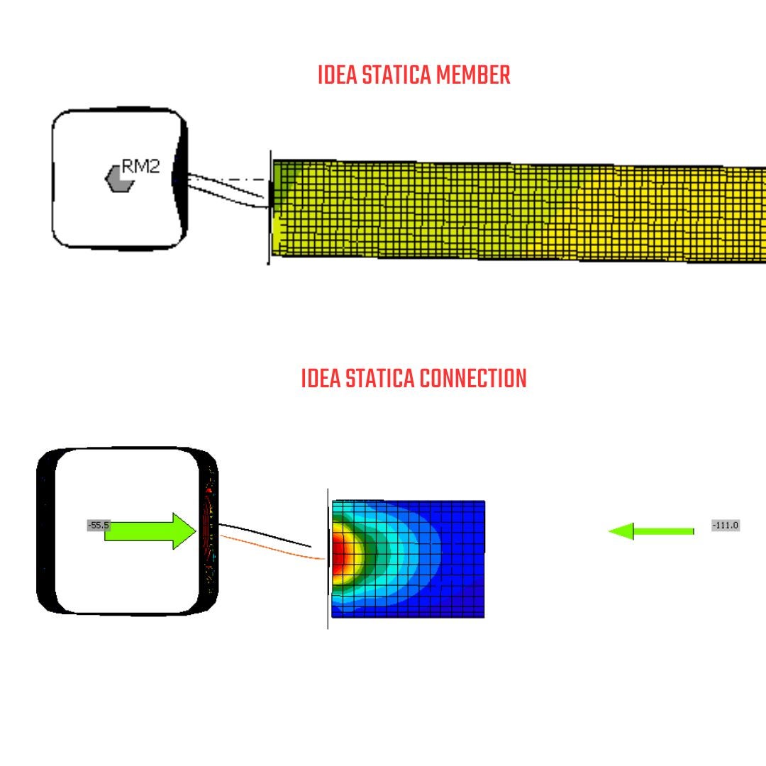
\[\textsf{\textit{\footnotesize{29) Deformation in Member and Connection comparison}}}\]
08. Linear Buckling Analysis
08.1. How it works in general
It predicts the critical load at which a structure becomes unstable due to buckling, assuming perfect geometry and elastic material behavior. It uses eigenvalue calculations to identify buckling modes and critical loads, serving as a first estimate for stability. While quick and idealized, it doesn't account for imperfections, non-linearities, or post-buckling behavior, requiring further analysis for real-world applications.
I would like to emphasize the astonishing explanation and visuals in the ANSYS tutorial. Feel free to check it out here.
Eigenbuckling analysis:
- linear method
- predict theoretical buckling strength
- computationally efficient
- multiple buckling modes
08.2. How it works in general in IDEA StatiCa Connection
The process of buckling calculation consists of two steps. In the first step, a stress and strain analysis is conducted to determine the initial stress state and the relevant stiffness. In the second step, the model types (boundary conditions) are altered, and buckling is calculated for the model with different restraints. The differences in how the constraints change are illustrated in Figures 31 and 32 below.

\[\textsf{\textit{\footnotesize{30) Model type N-Vy-Vz-Mx-My-Mz and buckling (just illustrational figures)}}}\]
\[\textsf{\textit{\footnotesize{31) Model type N-Vy-Vz and buckling (just illustrational figures)}}}\]
08.3. Linear Buckling Analysis in IDEA StatiCa Connection - MNA vs. GMNA - N-Vy-Vz-Mx-My-Mz
If you compare and evaluate the differences between MNA and GMNA as the base states for linear buckling analysis with consideration of model type N-Vy-Vz-Mx-My-Mz, you can observe:
- Mode shape for MNA and GMNA match
- The critical buckling factor is 52 for MNA and 79 for GMNA. The differences in these values arise from the varying load levels in the base state. By multiplying the critical factor by the current loads for each analysis level, you will obtain the similar critical load
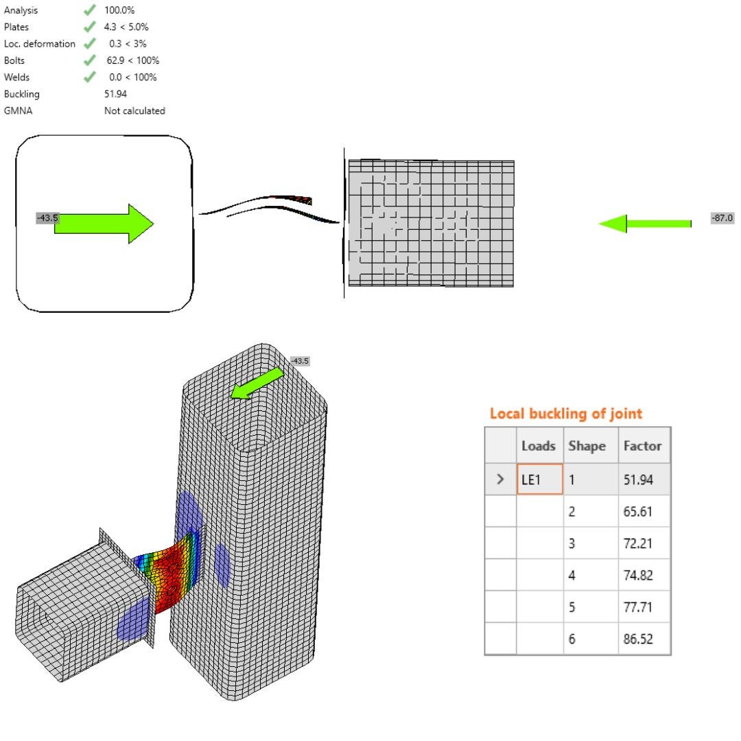
\[\textsf{\textit{\footnotesize{32) Linear Buckling Analysis - first step MNA }}}\]
\[\textsf{\textit{\footnotesize{33) Linear Buckling Analysis - first step GMNA }}}\]
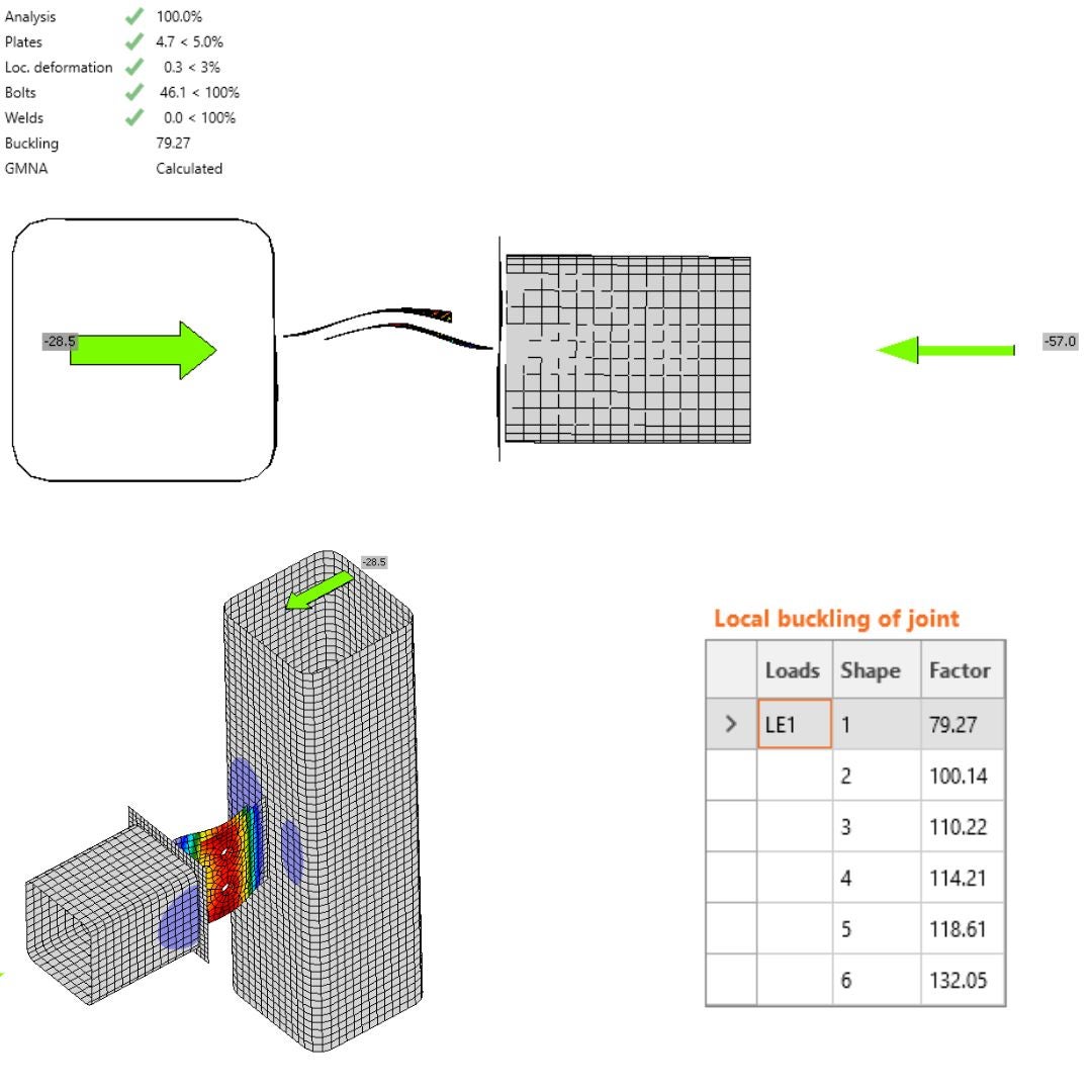
08.4. Linear Buckling Analysis in IDEA StatiCa Connection - MNA vs. GMNA - N-Vy-Vz
If you compare and evaluate the differences between MNA and GMNA as the base states for linear buckling analysis with consideration of model type N-Vy-Vz, you can observe:
- The first mode shape closely resembles the third buckling shape from IDEA StatiCa Member(figure 23), due to the free translational degrees of freedom for horizontal and vertical motion
- The buckling factor has dropped down and is lower for MNA than GMNA due to different load levels in stress and strain analysis.
- Another observable effect is the second mode shape that passes with the model type N-Vy-Vz-Mx-My-Mz figure 32,33.
- The buckling factors corelate with IDEA StatiCa Member for local buckling of plate, it means third buckling shape in IDEA StatiCa Member is equal first buckling shape in IDEA StatiCa Connection.
\[\textsf{\textit{\footnotesize{34) Linear Buckling Analysis - first step MNA }}}\]
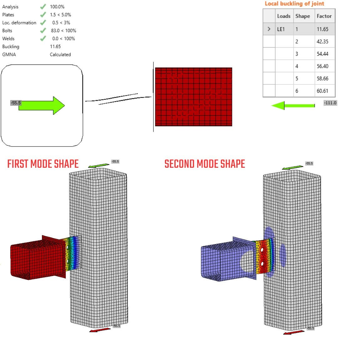
\[\textsf{\textit{\footnotesize{35) Linear Buckling Analysis - first step GMNA }}}\]
08.5. Linear Buckling Analysis in IDEA StatiCa Member
The buckling shape in IDEA StatiCa Member accounts for the stiffness of connections and considers the actual length of the member. This leads to the most accurate solution since all inputs are known, resulting in precise responses. A key attribute is also a critical factor that indicates how close you are to instability. This information is fundamental according to code requirements, as it helps determine whether you need to conduct a higher level of analysis, such as Geometrically and Materially Nonlinear Analysis with Imperfection (GMNIA), or whether you can rely on the Material Nonlinear Analysis (MNA) and remain perfectly safe. The first two buckling shapes undertake the global buckling that cannot be captured in IDEA StatiCa Connection. The third buckling shape pass with the first in IDEA StatiCa Connection.
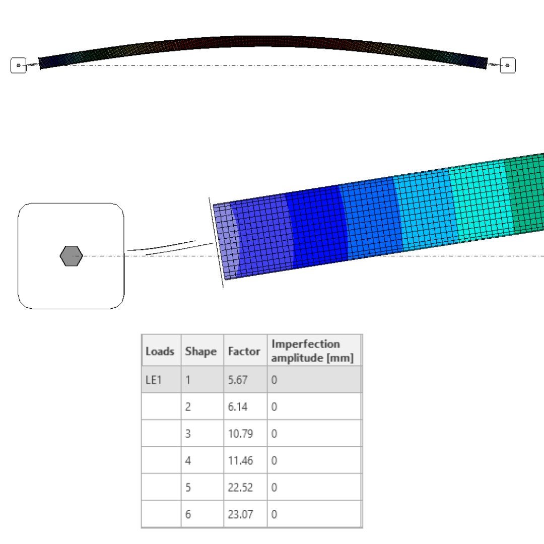
\[\textsf{\textit{\footnotesize{36) Linear Buckling Analysis - IDEA StatiCa Member }}}\]
08.6. Main Takeaways of Linear Buckling Analysis in IDEA StatiCa Member
- The first recommendation for eccentrically assembled connections -> use model type N-Vy-Vz, run MNA analysis, and use the instructions in this article for shear force value.
- The IDEA StatiCa Connection addresses only local buckling instabilities. Global buckling is the governing factor and should be checked using global FEA or preferably in IDEA StatiCa Member, considering connection stiffness.
- The IDEA StatiCa Connection focuses on local buckling only, which means it can overlook global buckling shapes. Therefore, it's crucial to check for global buckling first. A good approach to understanding the dominant buckling shapes is to model the submodel in IDEA StatiCa Member. By using the submodel, you can avoid errors and effectively capture both global and local buckling in one place.
- The N-Vy-Vz-Mx-My-Mz is the inappropriate model type for asymmetrically built gusset plate for MNA and LBA.
- The global imperfection should first be associated and analyzed in the global FEA, projected as the load or additional imperfection to the member model. Disregarding this imperfection can lead to underestimating the structural design.
Csatolt letöltések
- Models.zip (ZIP, 402,3 MB)