Prestressed beam with openings (EN)
1 New project
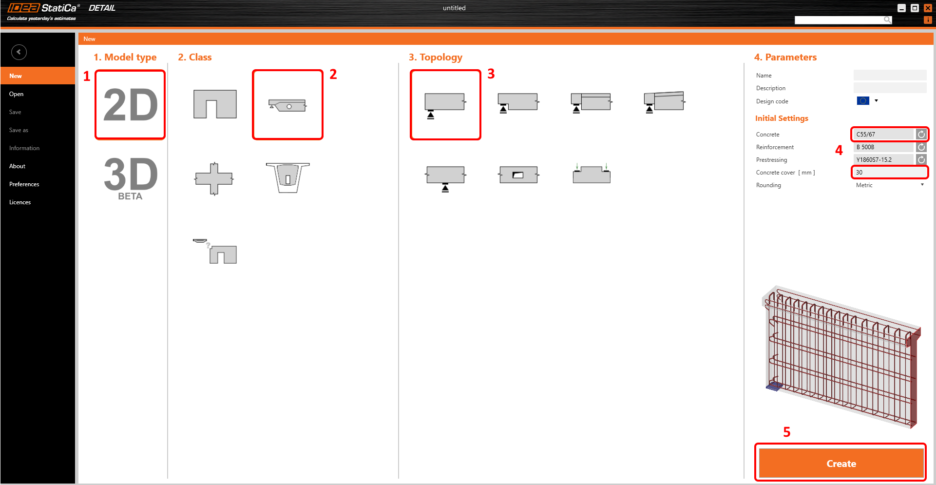
Start a New project in IDEA StatiCa Detail.

In the Wizard, set the concrete and reinforcement grade and define the Concrete cover thickness. Select the Beams class and End support topology.
2 Geometry
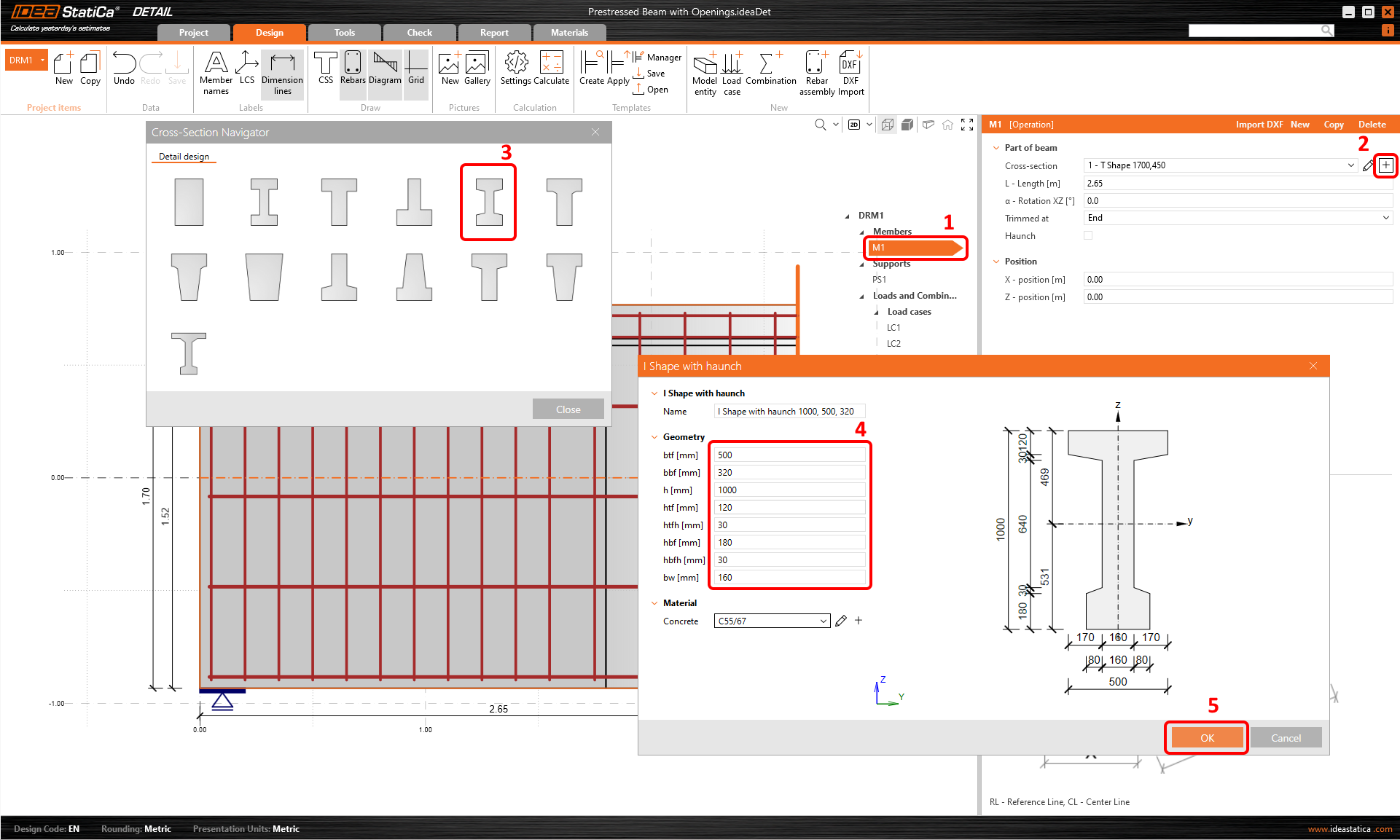
First, define the cross-sections. Two I-shape sections will be used. Select Member M1 (1), click on the plus button (2) and select the I-Shape with haunch (3). After that modify the Geometry (4) of the section.
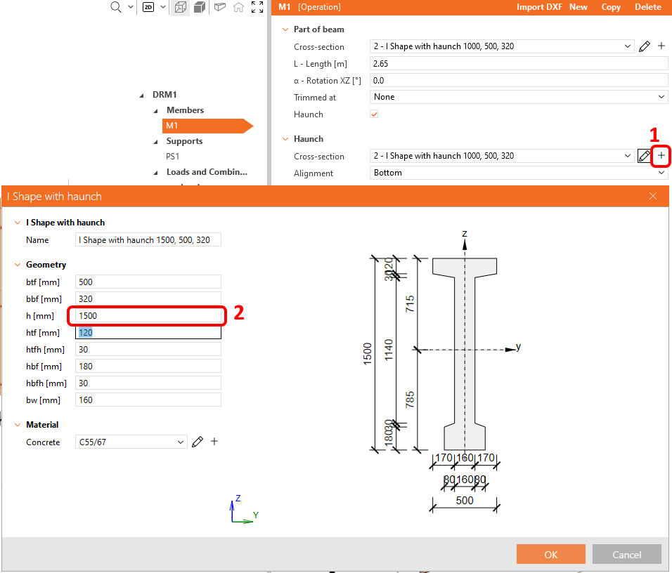
Modify beam M1, you have to turn off the trimmed end, add haunch and define the second cross-section.
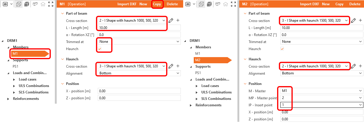
Select the proper cross-sections, and adjust the length and alignment. When the beam M1 is set, click on copy button to create the second part of the beam. Then modify the M2 beam.
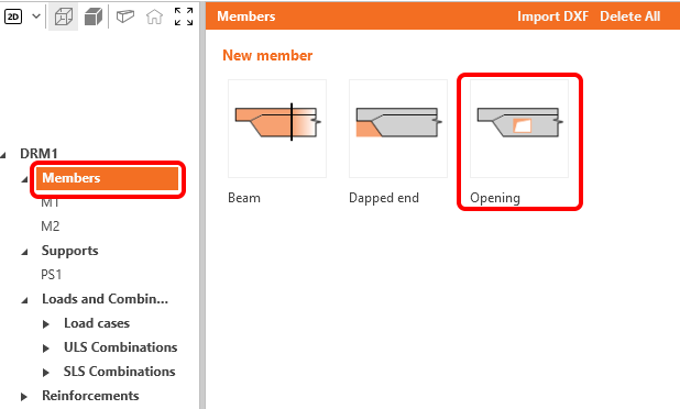
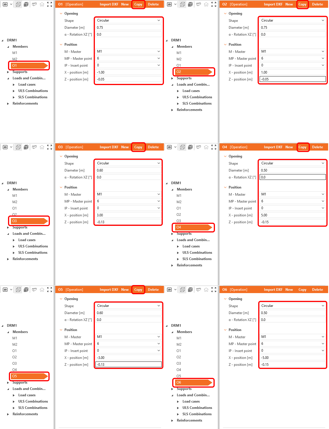
Add an opening.
Modify the geometry of the opening O1. Once you are done click on the copy button to create a new opening O2. Then proceed in the same way with the other openings. You can see the geometry settings below.
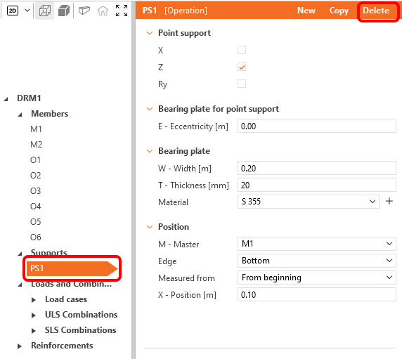
Next items to update are the supports. There are several types of supports in the Detail application. Delete Point support PS1 which was created by the template.
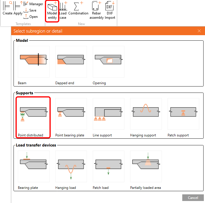
Add new Model entity, select Point distributed support to create new support.
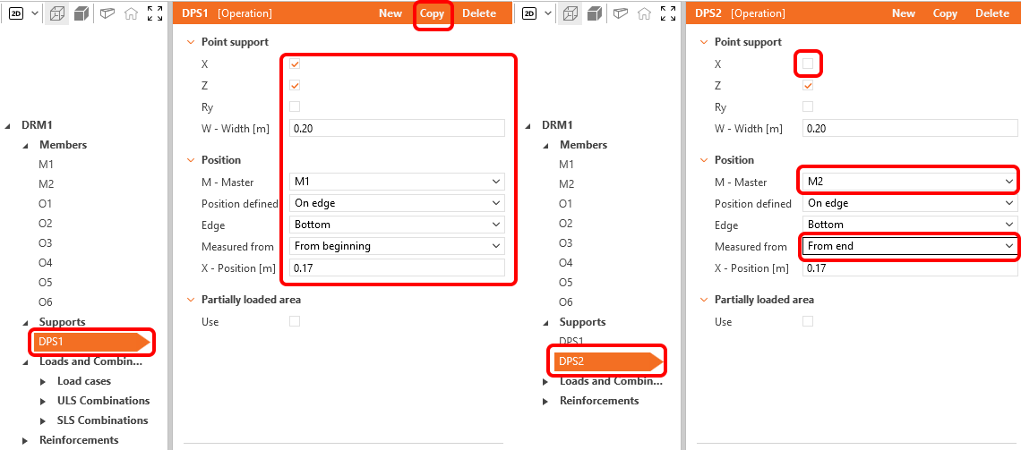
Set the Distributed point supports DPS1 according to the figure below. Copy the support and adjust the new support DPS2.
The geometry of the beam is set, your beam should look like this:

3 Loads
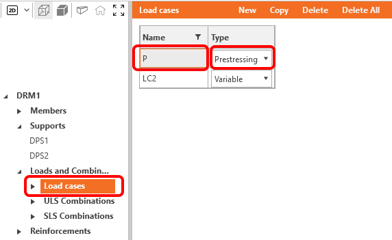
Go to the Load cases in the Tree menu. Rename the Load case LC1 to P and change its Type to Prestressing.
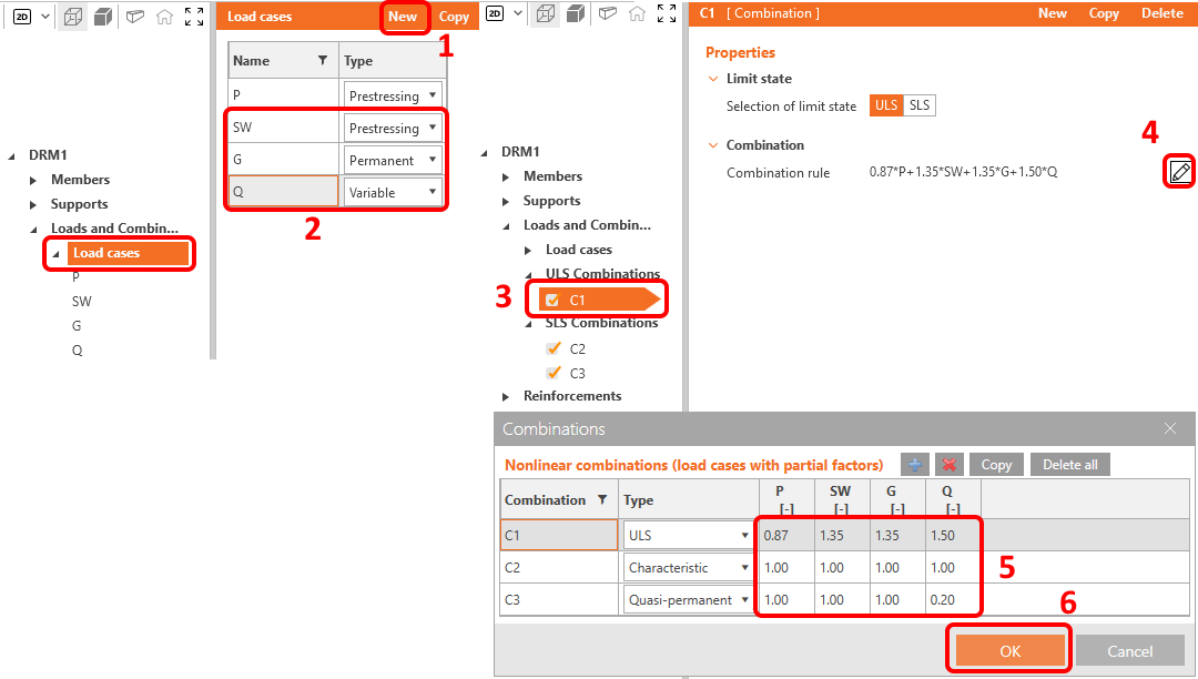
Add two new Load cases by clicking on the New (1) button. Rename and set the Load type (2) of all remaining load cases. Select combination C1 (3). Click on the pencil button (4) and modify the combinations factors (5). Confirm changes (6).
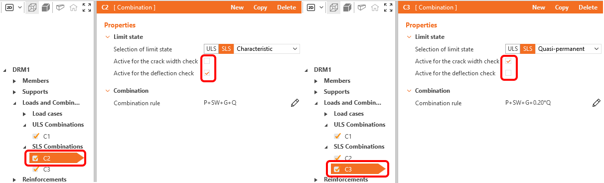
Each SLS Combination can be active for crack width check, deflection check or for both. Let's set C2 as active for deflection check and C3 for crack width check.
Leave all combinations C1, C2, and C3 checked. Note that the calculations will be performed only for the checked items.
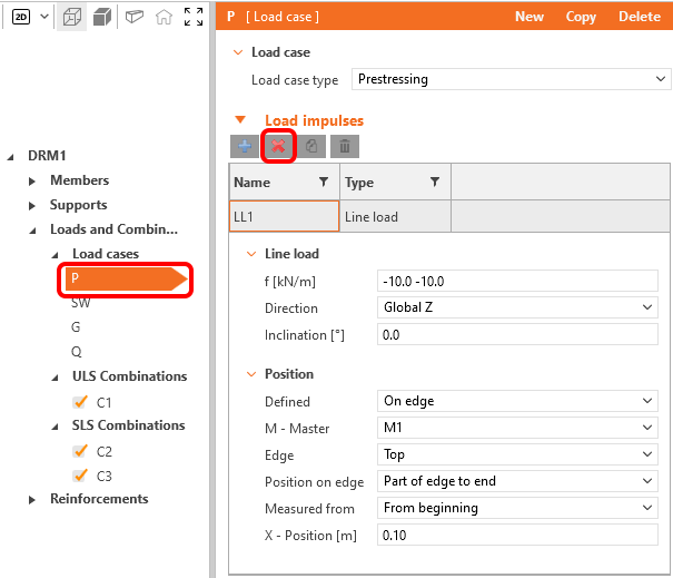
Let us start editing the Load impulses. Delete the Line load LL1 from load case P. This load case will stay empty.
Toggle the Current load case to SW. Delete all loads in this case. Click on the plus button and apply the Self-weight.
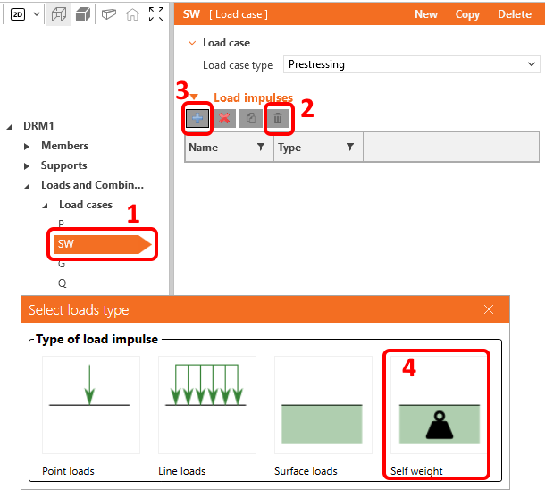
The self-weight was added to the load case SW, which is Prestressing Load type. It is important to read the Knowledge base article - How to set self-weight for prestressed beam in Detail. You will learn why is self-weight set as a prestressing load type.
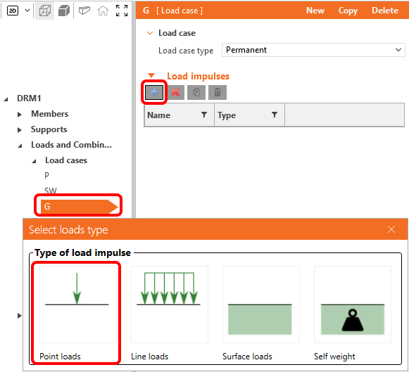
Add a Point load to the load case G.
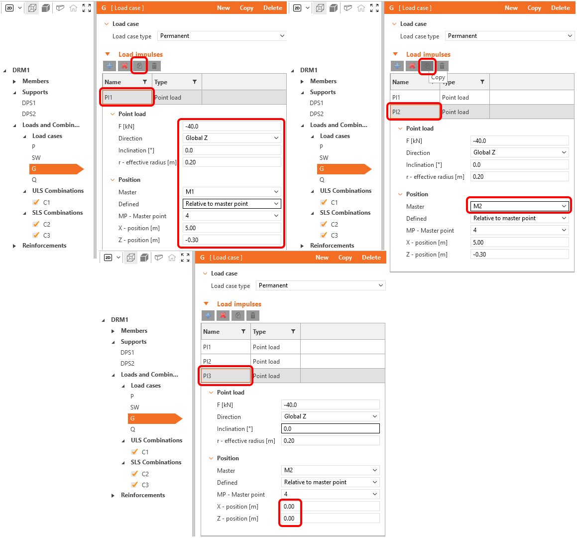
Set the Point load Pl1, and press the copy button. Then set the master member of the Point load Pl2 to M2 and again click on the copy. Pl3 has to be moved to the middle of the span. Adjust the X and Y positions.
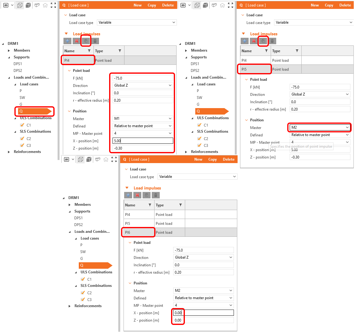
Similar point loads need to be created for load case Q. The only difference is the value of the load, which will be -75 kN.
4 Reinforcement
Once the load has been defined, you can proceed to define the reinforcement.
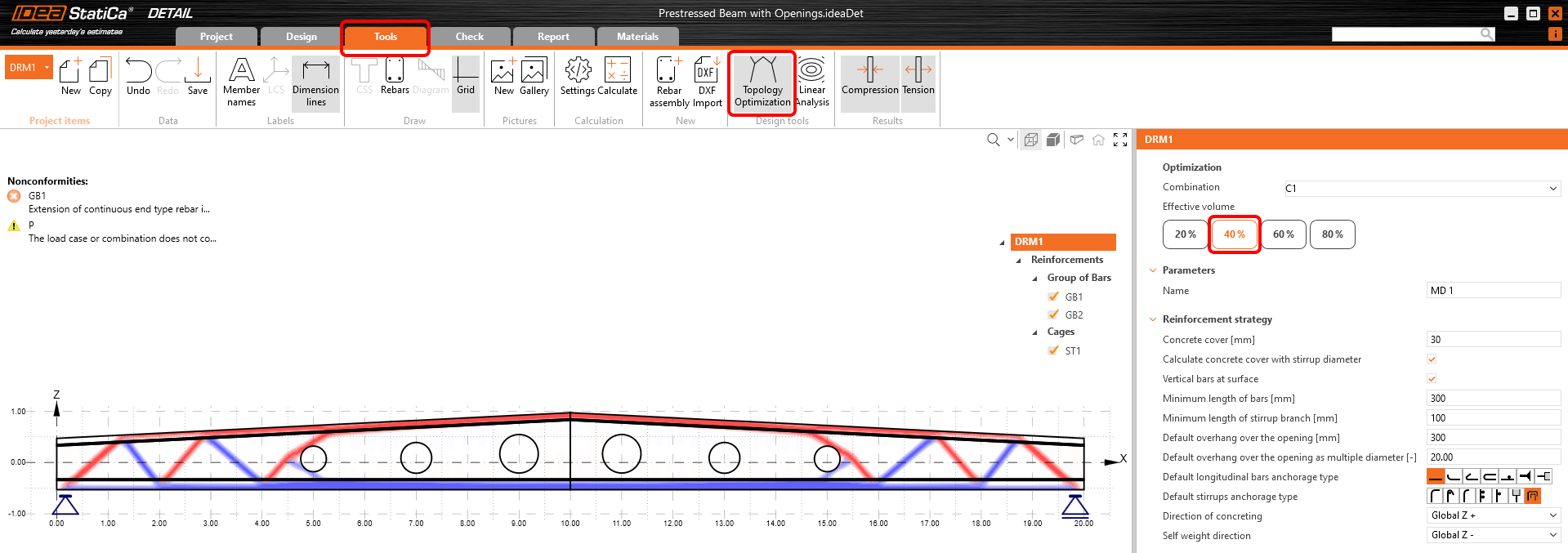
Let the Design tools display the regions with tension/compression. Turn on the Topology optimization. The calculation uses an effective volume of the structure (20%, 40%, 60%, or 80%) and, within several iterations, places this volume in a way so the created topology is the stiffest possible.
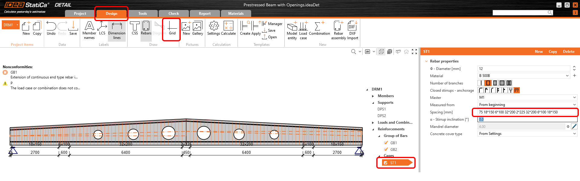
Now let's go back to the Design tab and turn off the Grid.
Gradually modify the reinforcement items. Let's start with Cages ST1, where the update of the Distances is needed. Distances are adapted to the shear stress, which is greater near the supports, and as you will see below the distances are densified in the area of anchorage of the prestresses wires.
The next item on the list is the longitudinal Group of bars GB1.
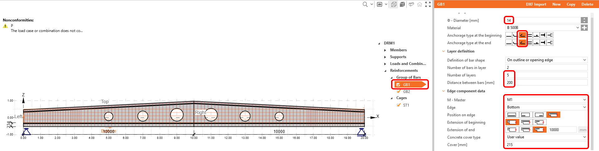
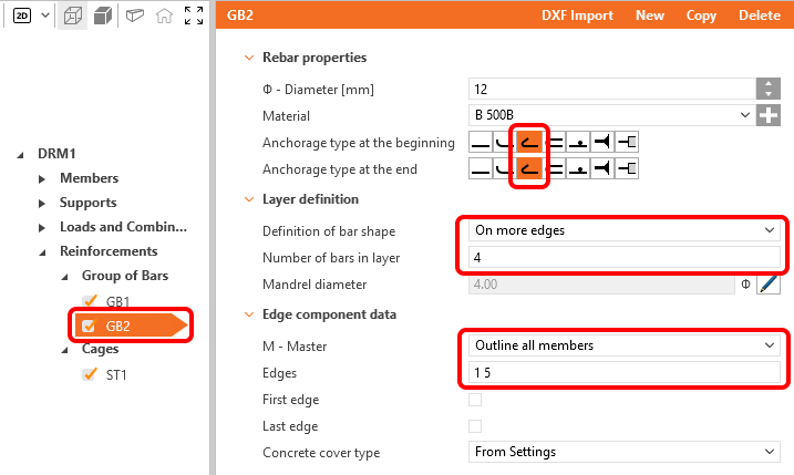
The top bars have to be modified too.
Last but not least reinforcement to be placed are the additional bars around the openings. Simply click on the New button and select the Cages Around opening.
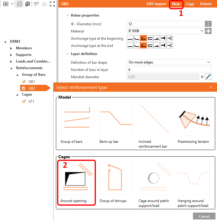
There are six openings, so you have to create six items of Reinforcement around the opening. All of them will be the same, only the M - Master has to be changed. First, modify the RO1 as follows.
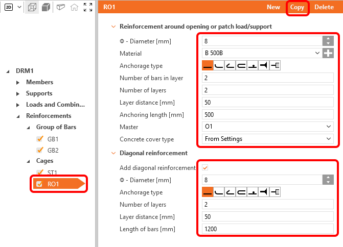
Then create another five copies of the cages, and assign the proper M - Master to each of the items.
The model is reinforced, and it should look like this.

5 Prestress
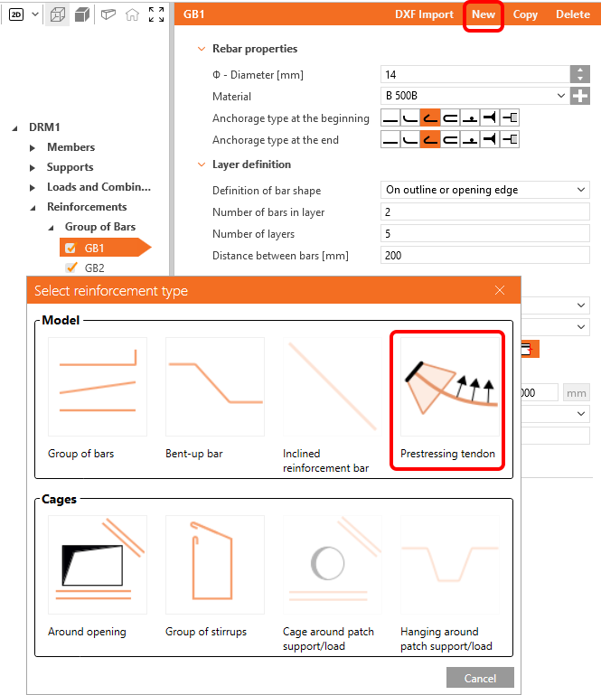
Cables and wires can be added analogously to the reinforcement. You have already created the Load case P, which will be used for the prestress. This roof beam will be prestressed by Pre-Tensioned wires.
Simply click on the New button and choose Prestressing tendon to create the first group of wires.
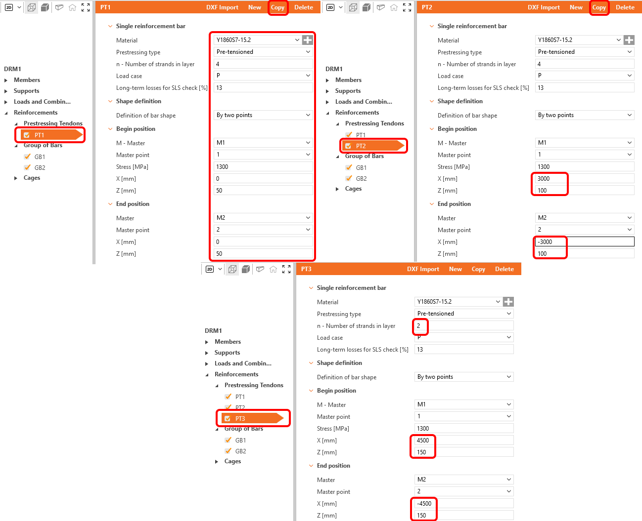
The three groups of wires are needed. Once you finish the process of modification of item PT1, you can copy it, adjust the geometry of PT2, copy PT2 and again modify the geometry of PT3.
The model is finally done.
6 Check
Go to the Check tab in the Navigator tabs and get the program to calculate your model.
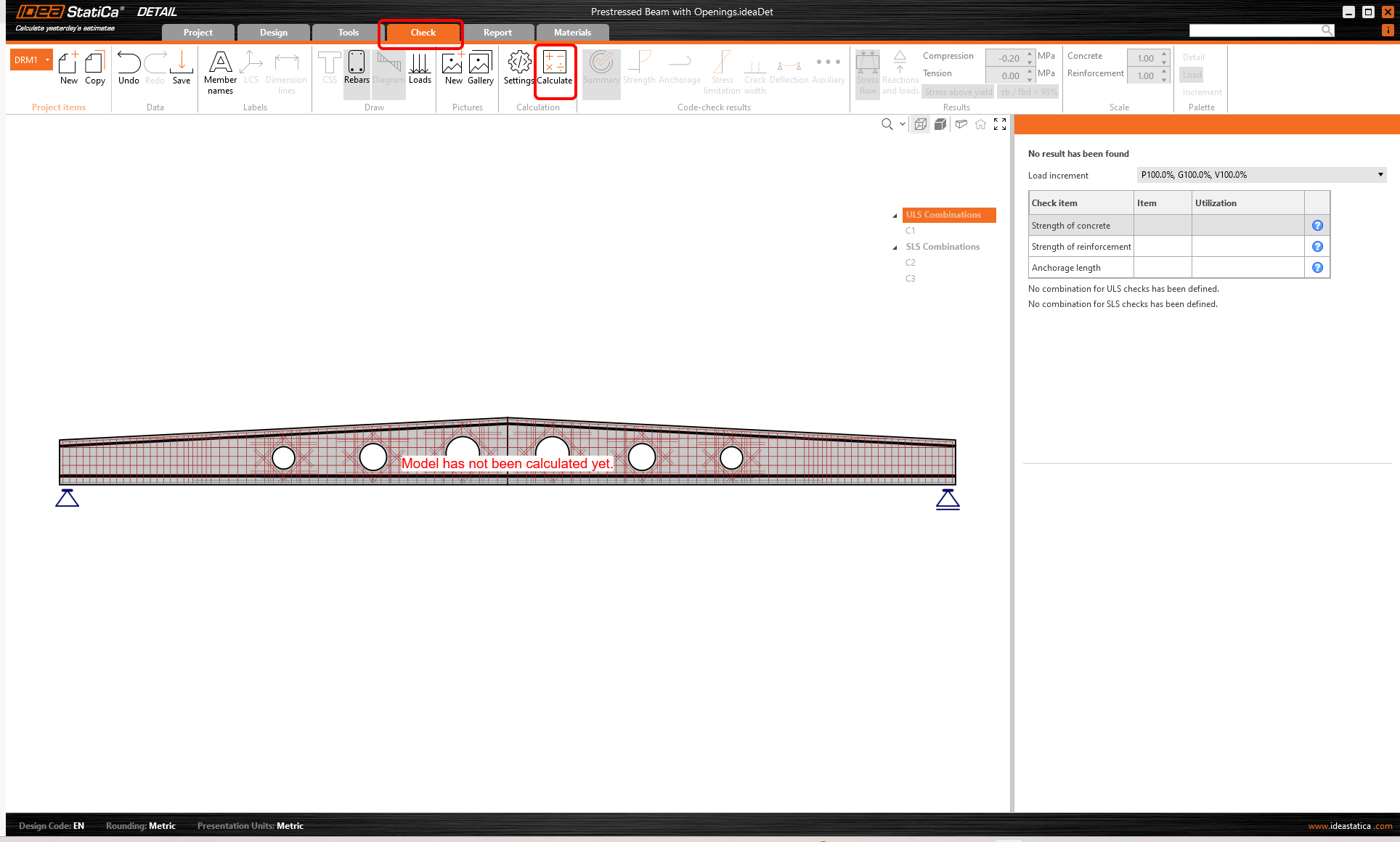
Once the analysis is done, you can go through the results.
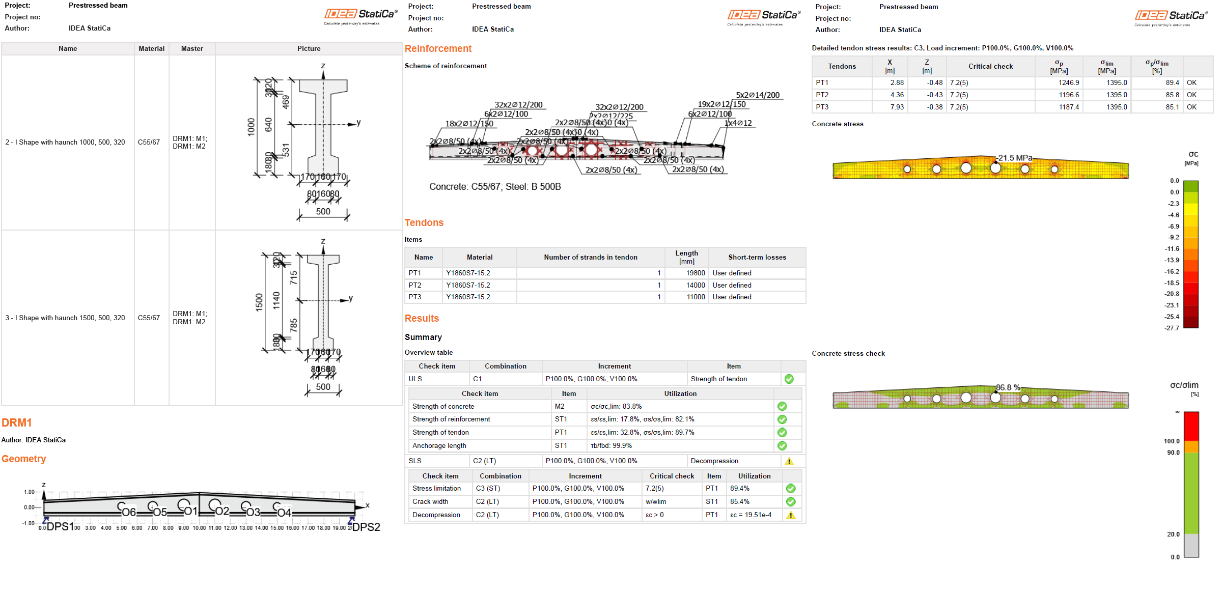
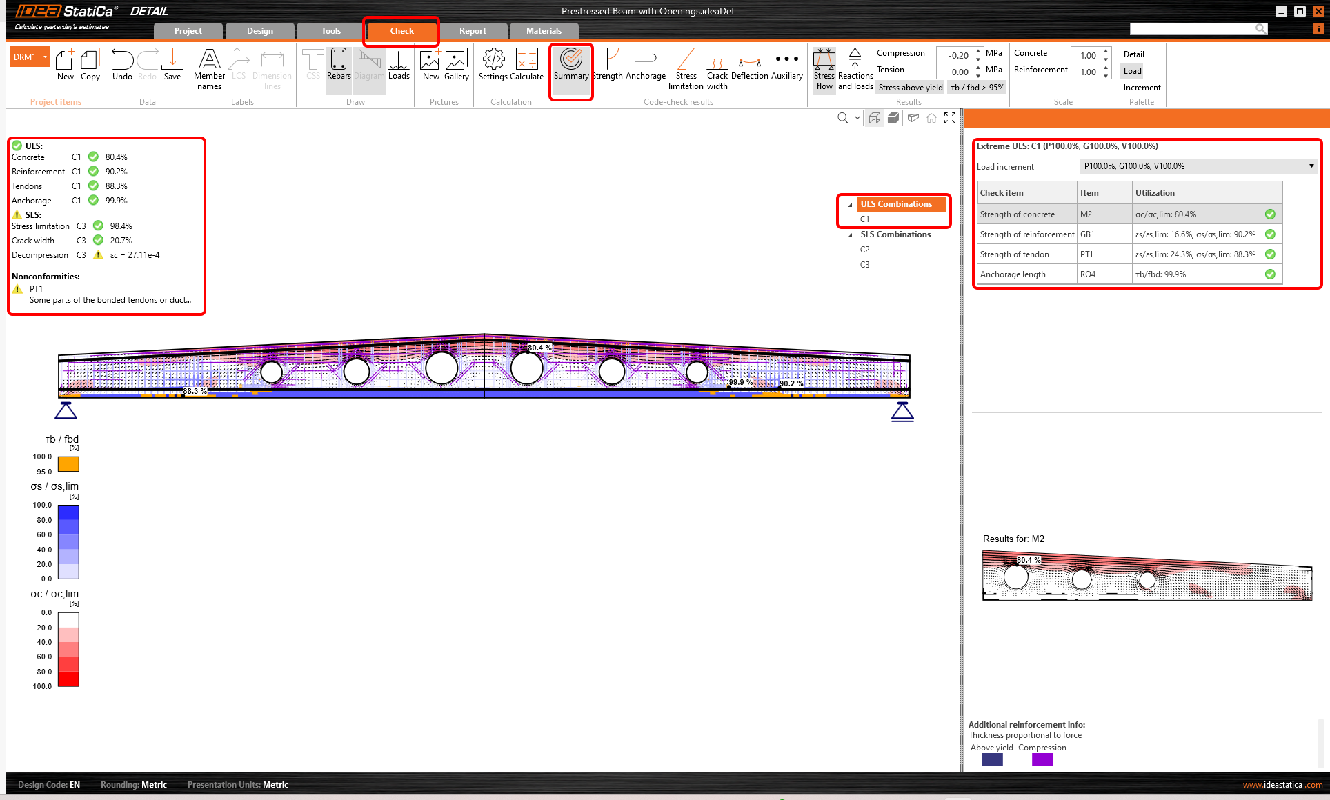
At the top left you can see a Summary of all the checks, the percentage utilization and the status of the checks (pass/fail). At the top right you can find detailed calculation results for the selected combination. Now the strength check of the concrete in ULS combination (C1) is presented. You can notice the portion of applied Prestressing, Permanent, and Variable load (P100%, G100%, V100%.)
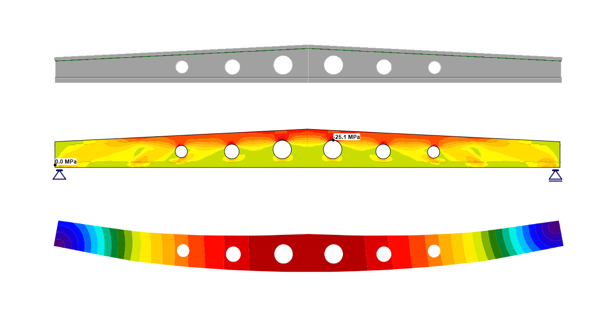
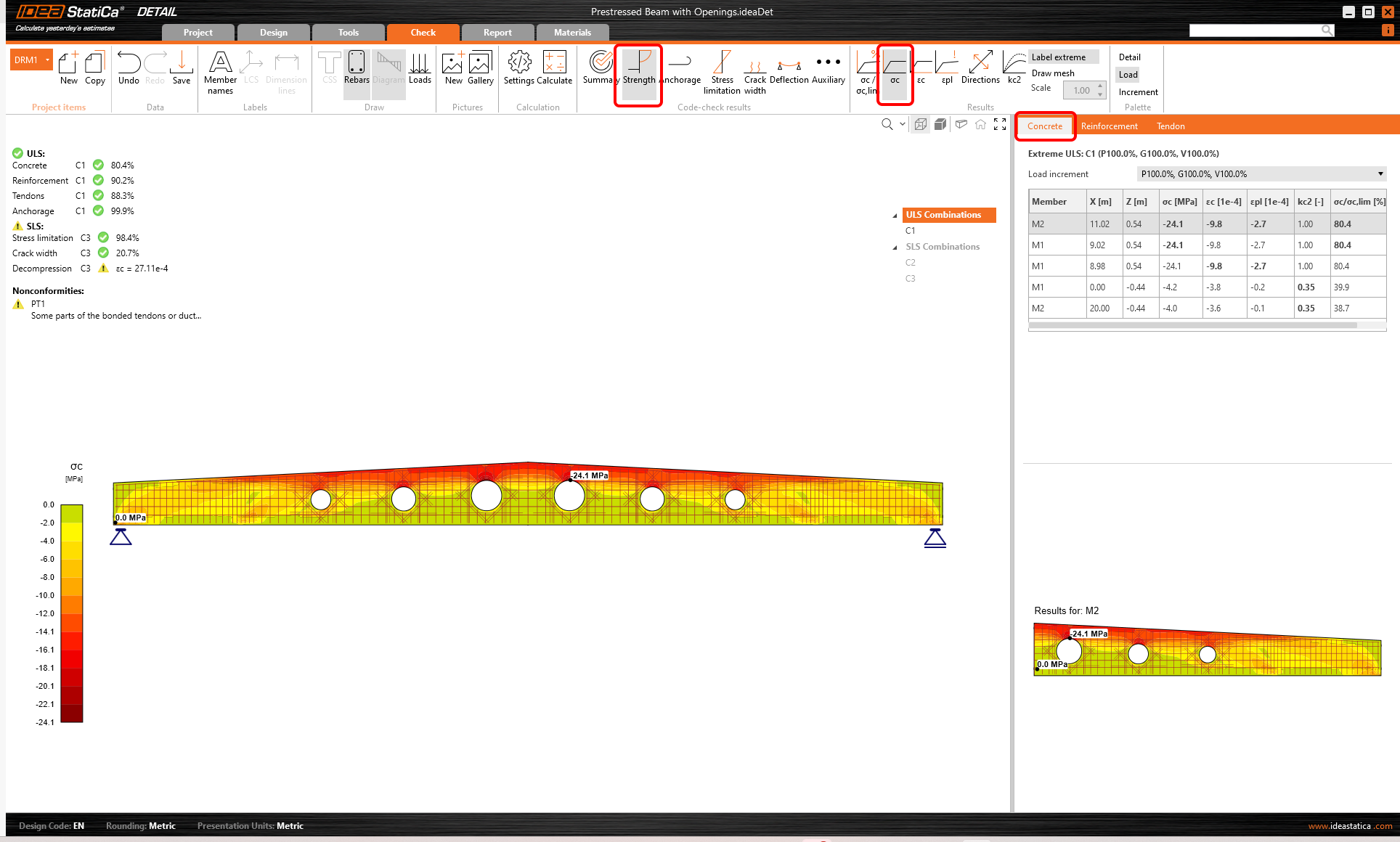
Switch to the Strength code-check results. This will open concrete ULS checks such as utilization in stress, stresses in principal direction, strains, and also a map of reduction factor kc. The C1 combination was used to check ULS.
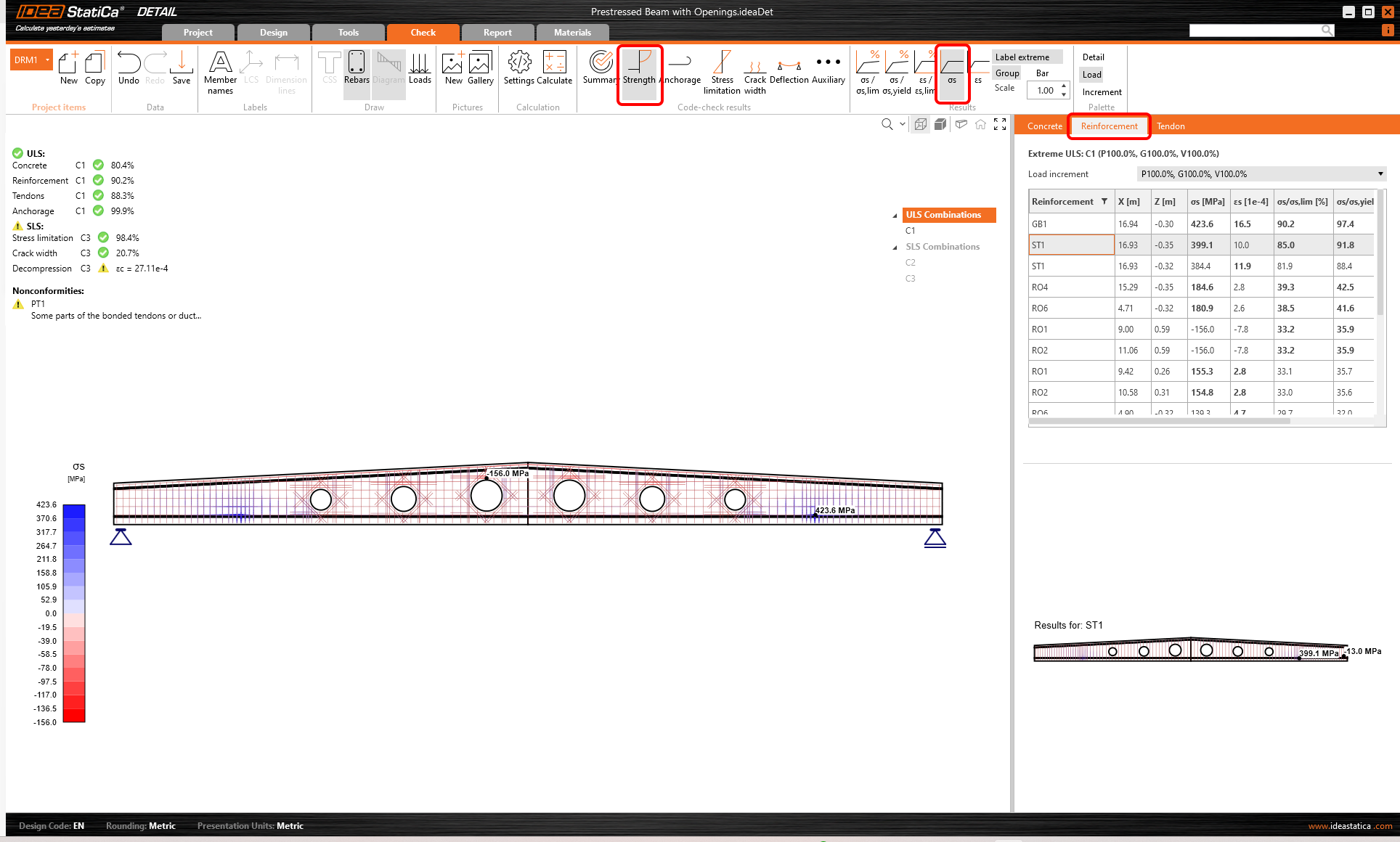
If you want to see such results for reinforcement, you need to click on the Reinforcement tab above the table. This will change the ribbon options and also the table for results. You can now display results for strains and stresses in each bar and their utilization.
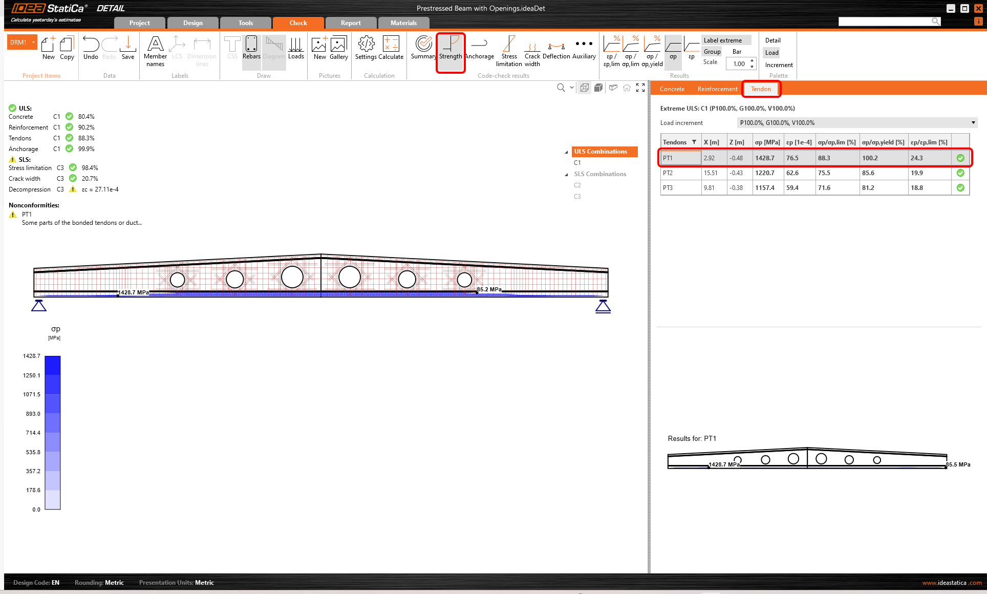
You can also display results for Tendons. Options are similar to the Reinforcement tab.
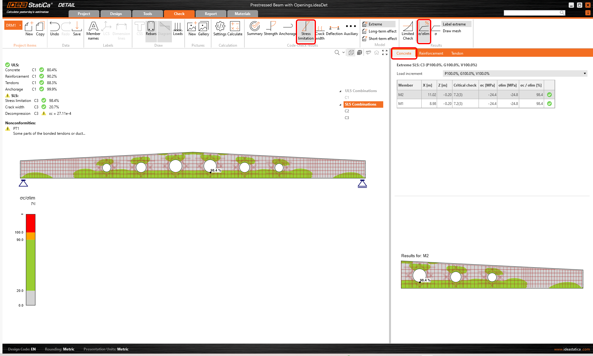
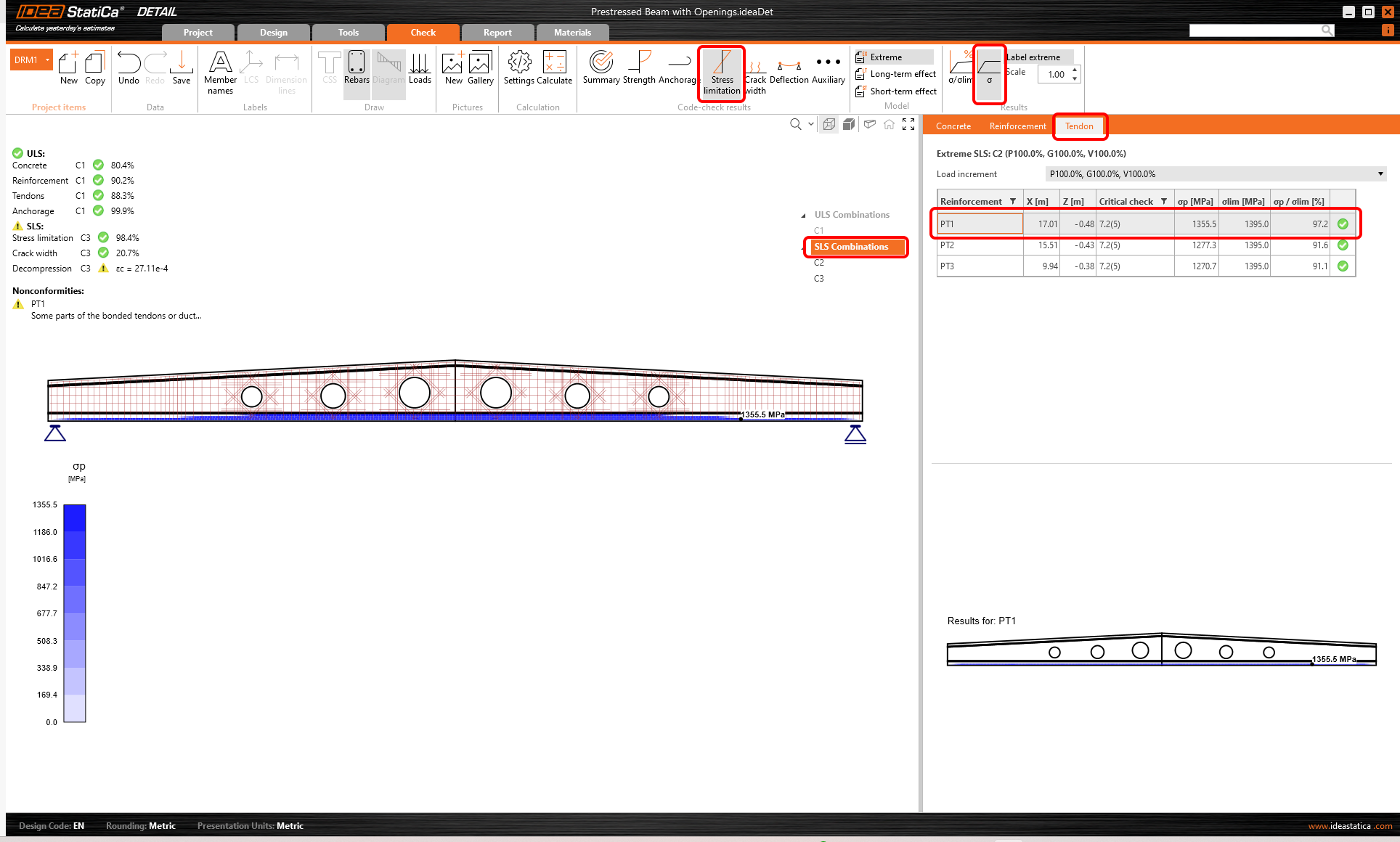
The results of SLS checks can be found in the Stress limitation, Crack width, and Deflection. For the Stress limitation state, the C3 combination was governed to check the concrete, while C2 to check also the reinforcement.
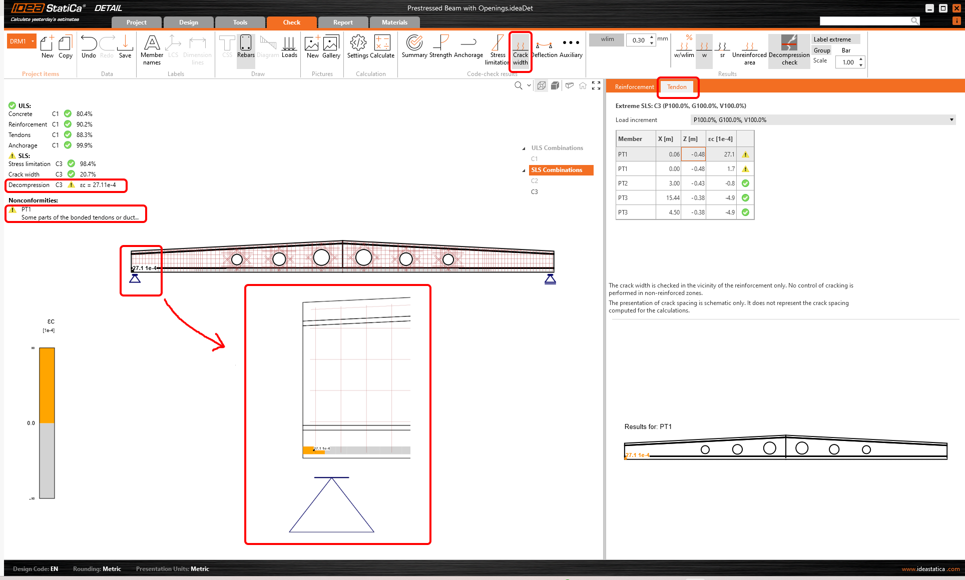
Select the Tendon tab. The code check will be displayed. The loads have to be properly assigned to the load types to obtain correct stresses in tendons. As it was mentioned above, reading the Knowledge base article - How to set self-weight for prestressed beam in Detail is needed.
Calculated crack widths can be displayed in the Crack width tab (combination C3). The calculated values are compared to the limit value wlim.
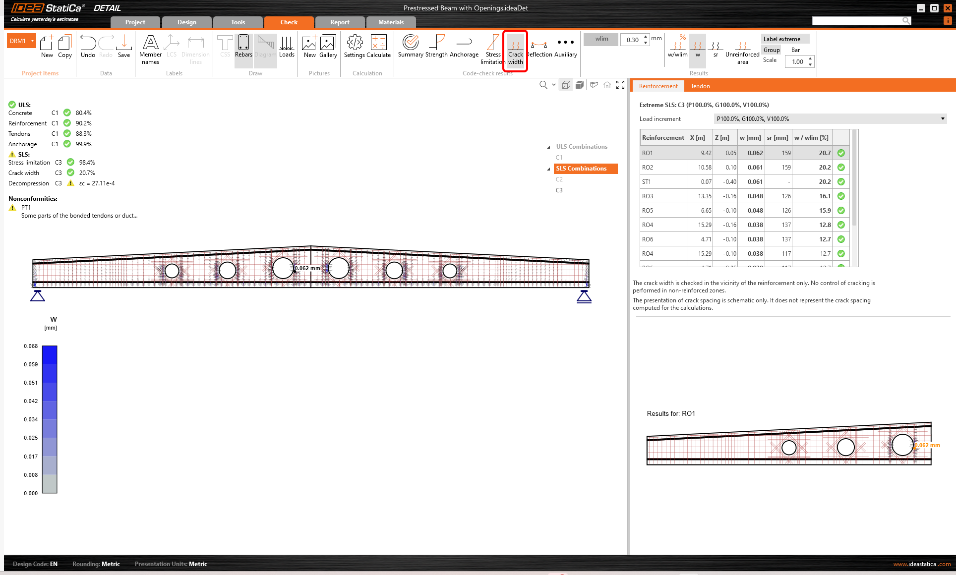
You don't need to worry about the warning regarding Decompression check. As you can see, the concrete is compressed along the entire tendon, the warning is only triggered by a numerical singularity at the very beginning of the tendon.
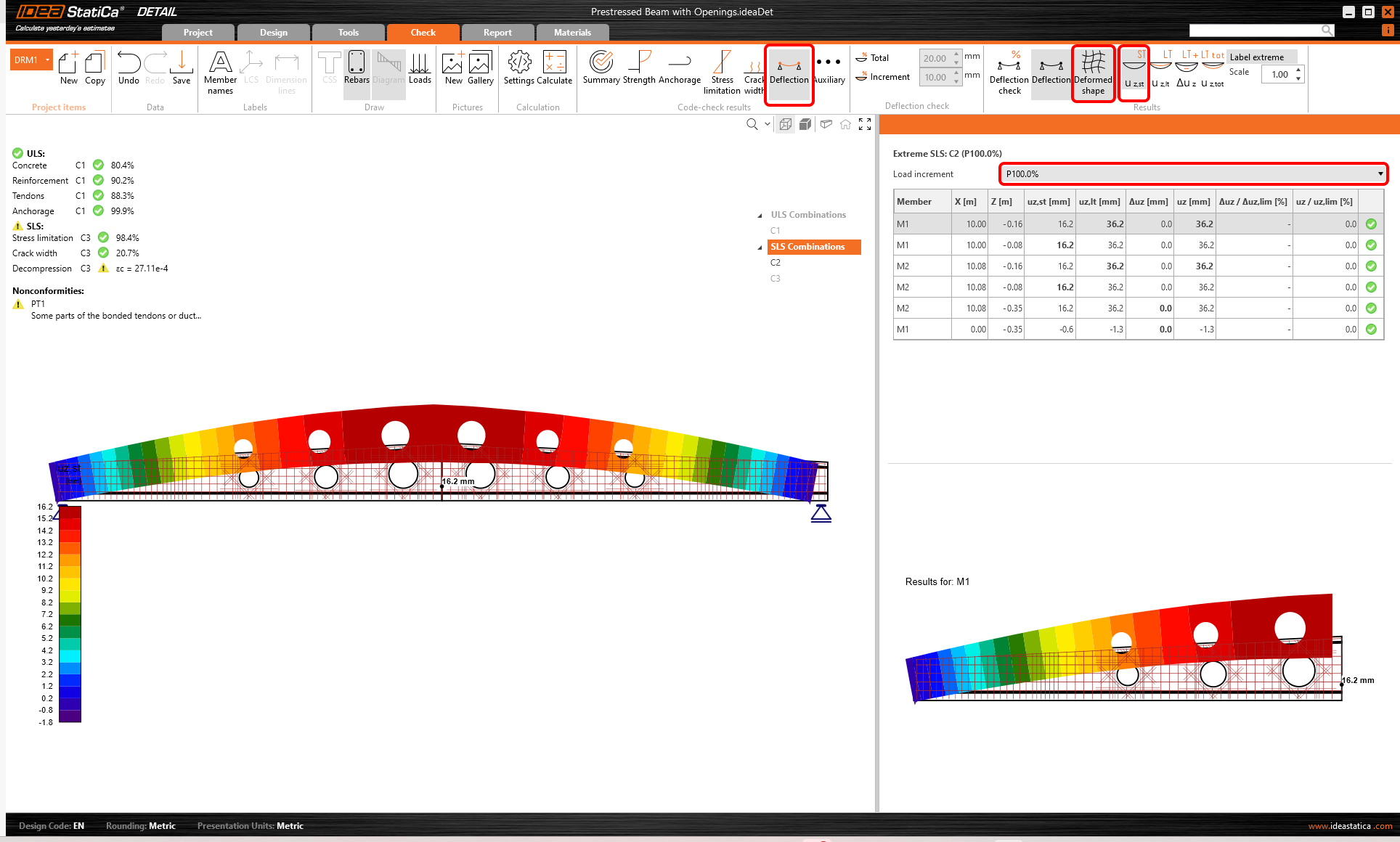
Last but not least, see the Deflection check. Deflections are available only for the load combination C2, as we previously set only C2 as active for deflection check.
You can display short-term and long-term deflections. Let us now display the short-term deformed shape for Prestressing load type. Please note, that you set the self-weight as Prestressing load type. So the displayed deformations are caused by self-weight and tendons.
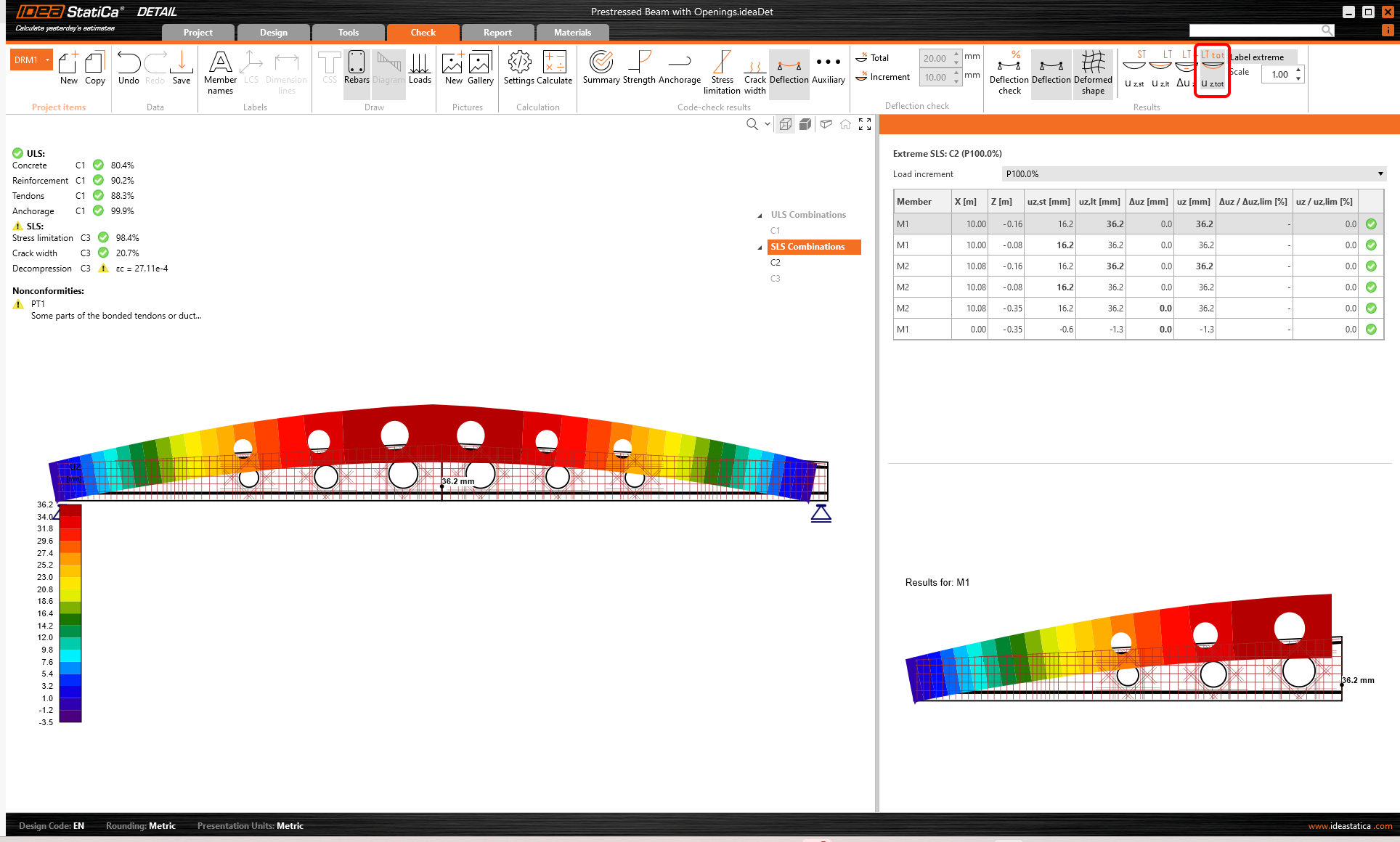
The long-term deformations are calculated using the creep coefficients. You can set the different coefficients for the Prestressing load type φpres and for the Permanent load type φperm to simulate the different times of application of these load types. You can set the coefficients in the Materials & models in the Project summary in the Navigator. The default values were left in this project.
To switch to the total deflections, simply click on uz,tot button.
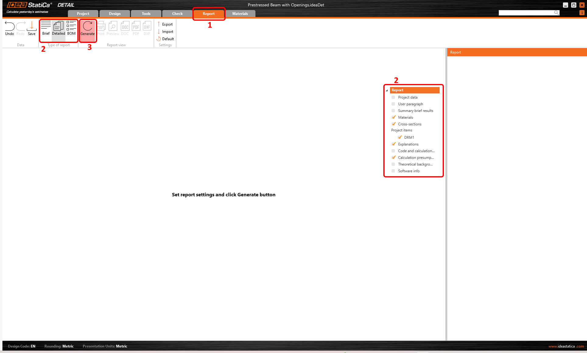
7 Report
At last, go to the Report tab. IDEA StatiCa offers a fully customizable report to print out or save in an editable format.