Stiffness and deformation capacity
Version 7 provides a new function that analyses the stiffness and capacity of a connection of any member in the joint. The complete diagram is generated automatically, is directly displayed in GUI and can be added into the output report. Rotational or axial stiffness can be studied for specific design loads. IDEA StatiCa Connection can also deal with the influence of other internal forces.
Diagram shows:
- Level of design load
- The limit value of capacity of connection for 5% equivalent strain
- Limit value of capacity of connected member (useful also for seismic design)
- 2/3 of limit capacity for calculation of initial stiffness
- Value of initial stiffness
- Limits for the classification of connection – rigid and pinned
Base plate, anchoring
V7 offers the option to input different offsets of a concrete block on different edges of the steel base plate. Offsets influence the calculation of the size of break-out cones.
End of anchors is frequently modified to increase cohesion and make a break-out cone bigger. However, in checks it is involved only in the size of break-out cone. Users can define washers of a specific size to make a break-out cone bigger. The washer can be rectangular or circular, but both have the same influence on the size of cone.
Rectangular washers Circular washers
Stiffening members
Users of IDEA StatiCa Connection can reinforce steel joints with additional plates – stiffeners, ribs, doublers. Segments of hot-rolled or cold-formed profiles can be used for stiffening in version 7. These stiffening members behave in the joint the same way as basic steel members – all manufacturing operations can be applied to them. Stiffening members cannot take loads. They are not a part of the 3D global model of the structure.
Contacts
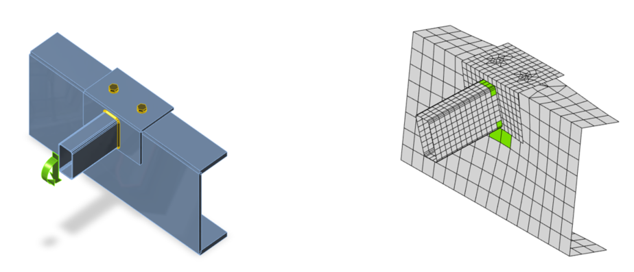
Steel connection is modeled like a system of plates (members are composed of plates), welds, bolts, and contacts. Contacts appear in places where two plates are in touch. They take 100% of the pressure but do not act in tension at all. Contacts are automatically generated between plates which are a part of bolted connection. Version 7 brings an option to define the contact between any 2 surfaces of plates even if they are not bolted together. A lot of practical technical tasks can be resolved thanks to this new feature.
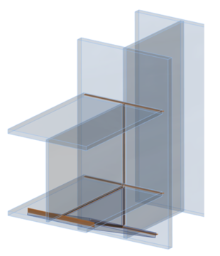
Contacts between web and flanges of 2 overlapped Z sections
Added profile, bolted on upper flange, contact on web
Stiffening member, flange supported by contact, no shear forces in bolts.
Link with SAP 2000
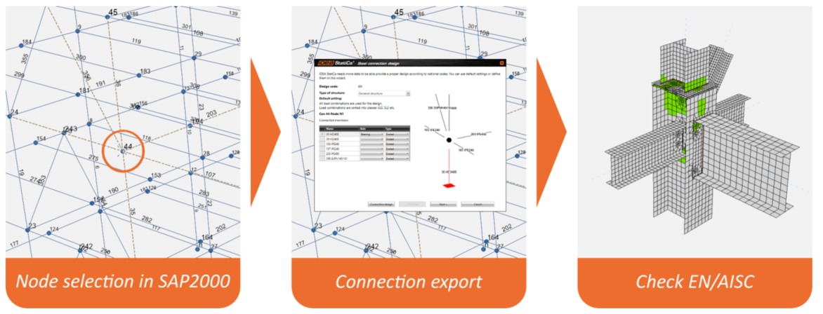
SAP2000 is a widely-used FEA structural software. IDEA StatiCa 7.0 can read all necessary data for the design of steel joints from SAP2000 3D models. IDEA StatiCa can read the whole SAP2000 project or only its part. For IDEA StatiCa Connection there is a simplified direct workflow - just select a node in SAP2000, click on an “IDEA Connection” plug-in and design the joint.
Improvements
Model of welds
Welds are an important part of any steel joint. Version 6 we use the model where the weld is modeled like a constrain between edge and surface of plates. Constrain itself does not have material properties. IDEA StatiCa calculates forces in constrains and offers evaluation using 3 methods - maximal/ average/ linear. IDEA StatiCa development team has been working on a much more precise model. Such where welds are also equipped with material properties. It means they can become plastic like all steel plates. This model will provide better results, especially for long welds. The effect called “effective length of weld” will be taken into account already in calculated results. Plastic welds will be available once a thorough development and testing process finished but no later than by 1st October 2016.
What was improved for welds already in version 7: The geometry of the weld position was rebuilt. The real length of the weld is respected in case of different lengths of welded edges or in case of interruption of welds due to openings. The precise position of welds gives us the chance to improve the presentation of welds. Welds are rendered like in reality when using “solid“ mode. When using “transparent“ mode, the only line constrains between edge and surface are shown. This allows us to easily check the correct implementation of the weld. New geometry helped to improve the behavior of welds which are close to the edge of the plate where IDEA StatiCa can give nonsymmetrical results in symmetrical tasks. Thanks to this correction and improvement, the version 7 results can give a bit different results of stress in certain cases.
Presentation „solid“
Presentation „transparent“
Weld results table – new signs for weld type.
Import from Tekla Structures and Advance Steel
Both links were released in version 6. IDEA RS fluently improve it and enlarge supported functionality. Now we are able to do also this:
- Notches – it is possible for both plates of members and stiffening plates. Not for general 3D solid. Welds have to be added in Connection.
- Openings – we can read all openings in stiffening plates. Not yet in plates of members.
- Stubs – we can read cuts on both ends, thanks to the development of stiffening members
- Weld “all-around”
- Bended plates
- Cuts by CHS – everything is imported, cuts “by surface” have to be added manually
- Anchoring – partially improved, base plate still has to be added in Connection
Report
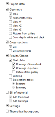
Output report has key value for the user so we improved its quality in version 7 – style of tables, labels. There is also direct export into MS word – program generates MHT file. We rearranged the “one-line” output. There is more useful information which makes the output more valuable. It works both for stress/strain and stiffness analysis.
“One line” report
There is a new export of drawings into DXF format in the Bill of material. Drawings can be opened directly in Autocad.
Pictures from bill of material into DXF
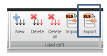
Loads – export into Excel file
The new function can be used for copying of load cases between items in the project or between different projects.
Cross-sections
One more cross-section type was added. Angle profile with the possibility to define the angle. It can be applied for stiffening member and used for modeling of bent plates.
Simplified UI
Setup dialog
2 setup dialogs were unified into one, only important values are available.
FEA setup was removed, Colours are moved to Preferences, only one setup dialog is available now.
Original Setup dialog was rearranged and several properties from FEA were added.
FE results
Settings In nodes / In elements were removed. IDEA StatiCa Connection uses “in elements” for all check CBFEM outputs and “in nodes” for FE results of stress and strain.
Report settings
Quite complex settings dialog for a detailed report is briefer now. We defined compulsory content of the report and the user can play only with a limited number of options.


