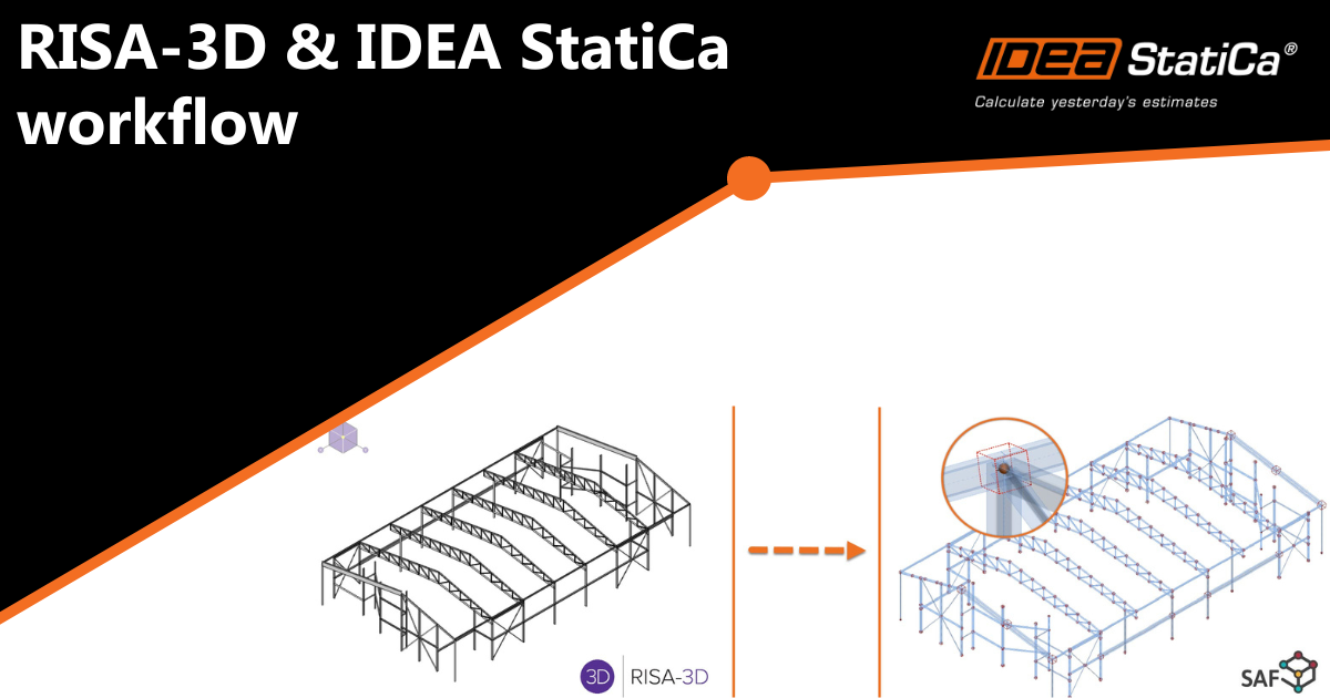
RISA-3D import into IDEA StatiCa
RISA-3D - IDEA StatiCa SAF file import
Notes: This SAF-based integration is developed and maintained by RISA. IDEA StatiCa is not involved in maintaining this integration. All technical requirements and questions should be addressed to RISA directly.
Workflow:
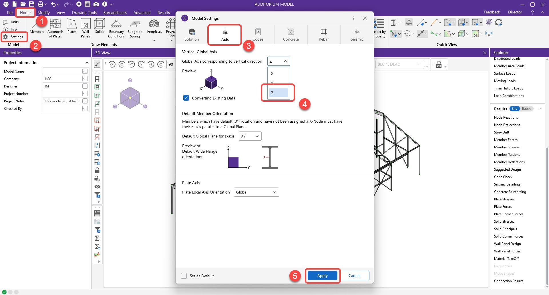
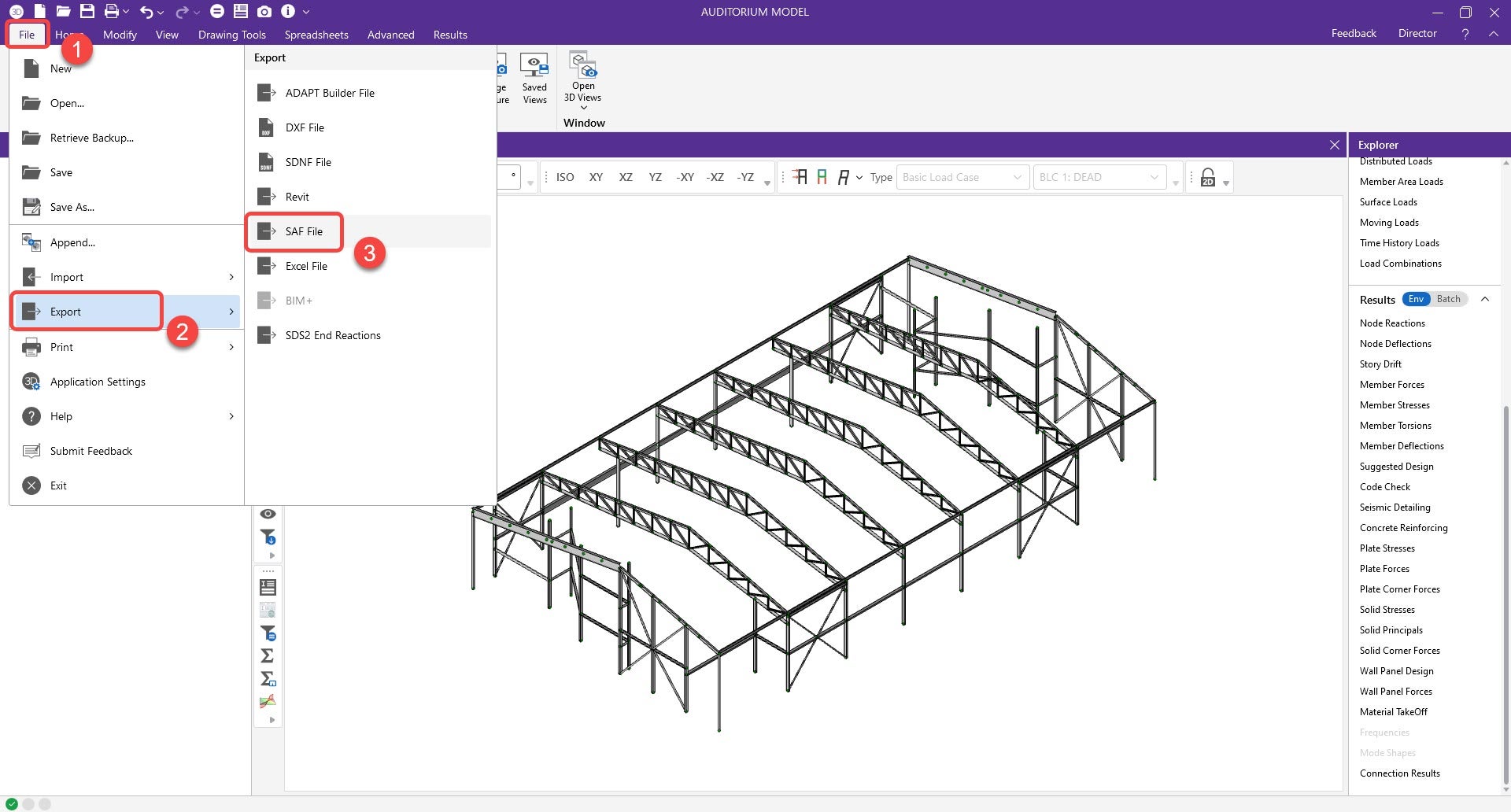
1. The user will create and save a SAF file from RISA. This option can be found under the export options. However, RISA will prompt a message stating that the Global vertical axis needs to change from Y to Z before exporting. The update will only change the global coordinate system (GCS), not the local coordinate system (LCS).
Note: Changing GCS from Y to Z can affect loading direction, such as member area load. You can save another copy of the RISA file, one for GBS adjustment and the other for analysis and results.
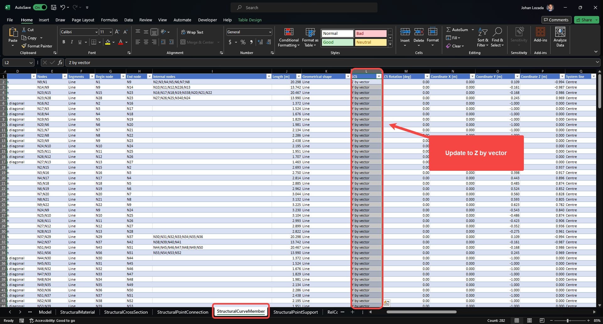
2. Open the SAF file before importing in Checkbot and go to the “StructuralCurveMember” sheet.
- Change column L (LCS) from “Y by Vector” to “Z by vector” in all the members.
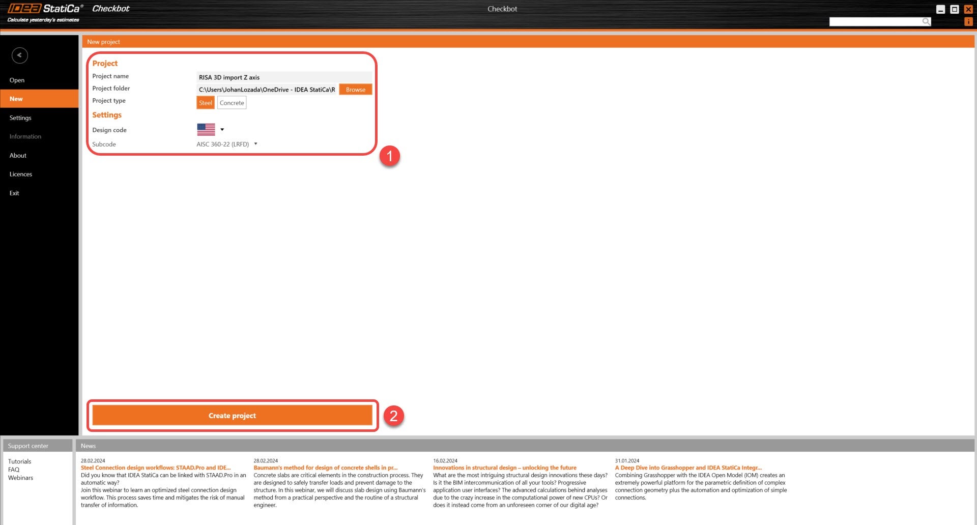
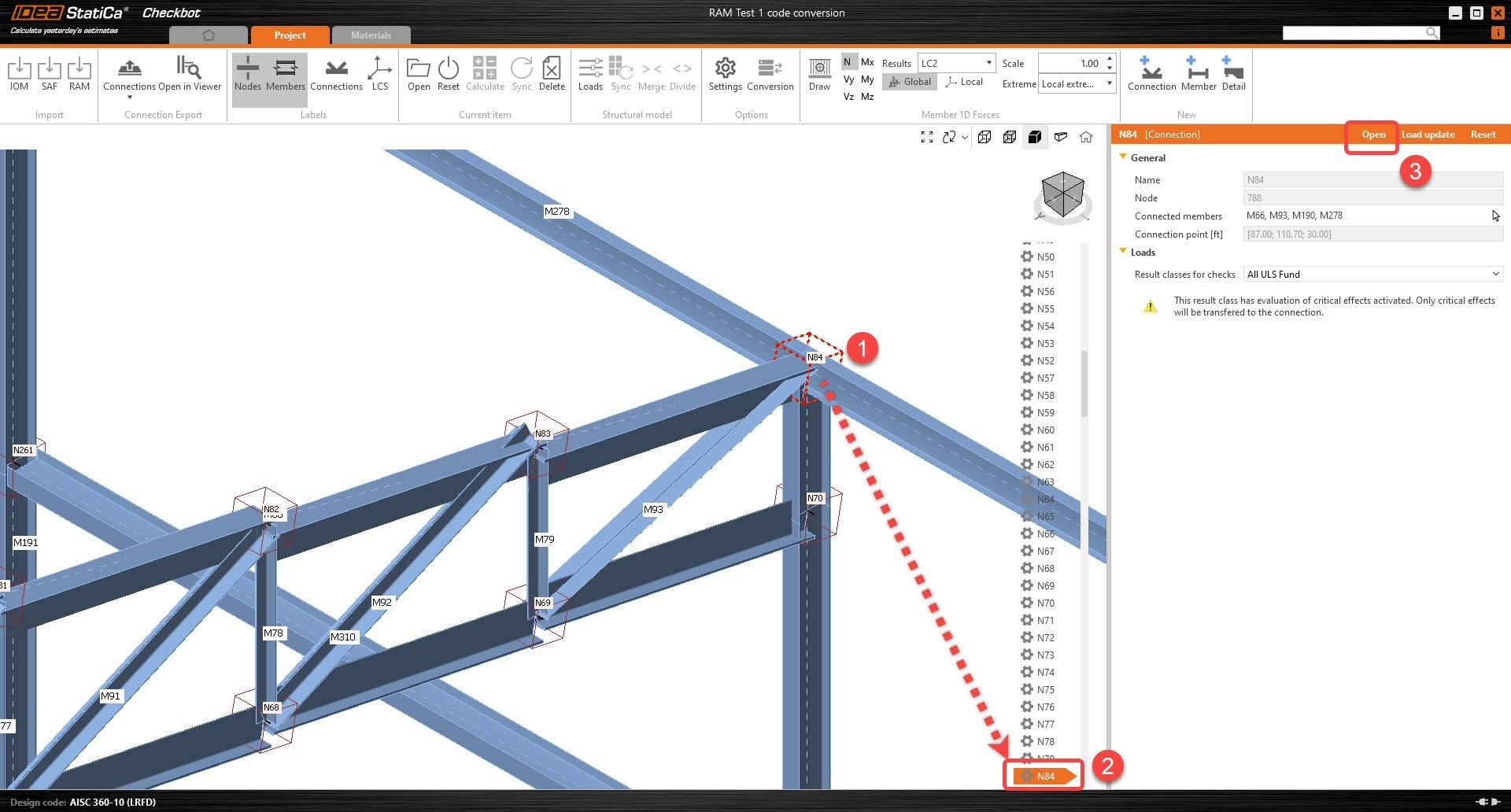
3. Create a new Checkbot project.
4. Import the model into the new IDEA Checkbot project.
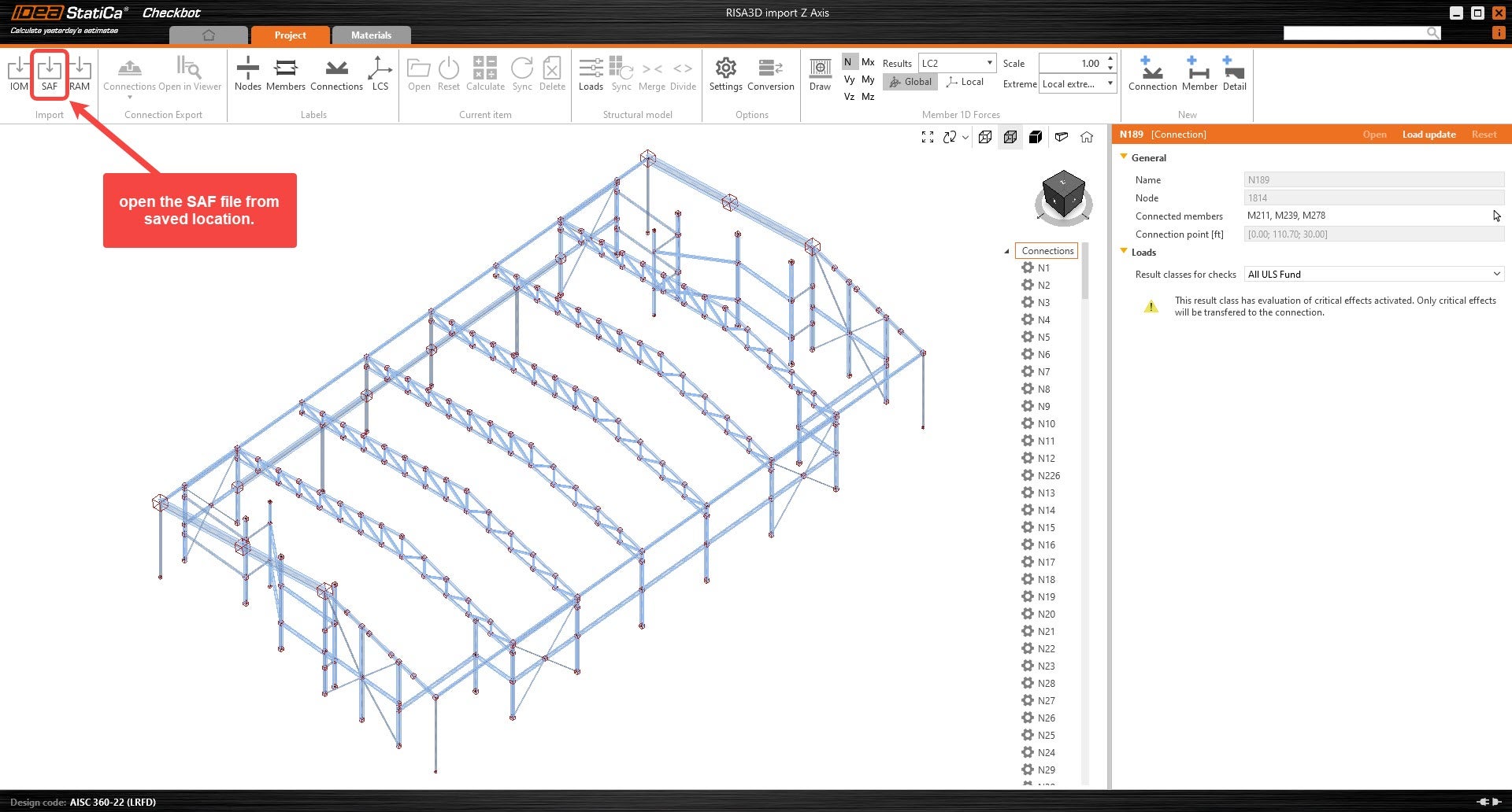
5. All symmetrical cross-sections will be rotated accordingly. For any non-symmetrical member that is not rotated correctly, follow the next steps.
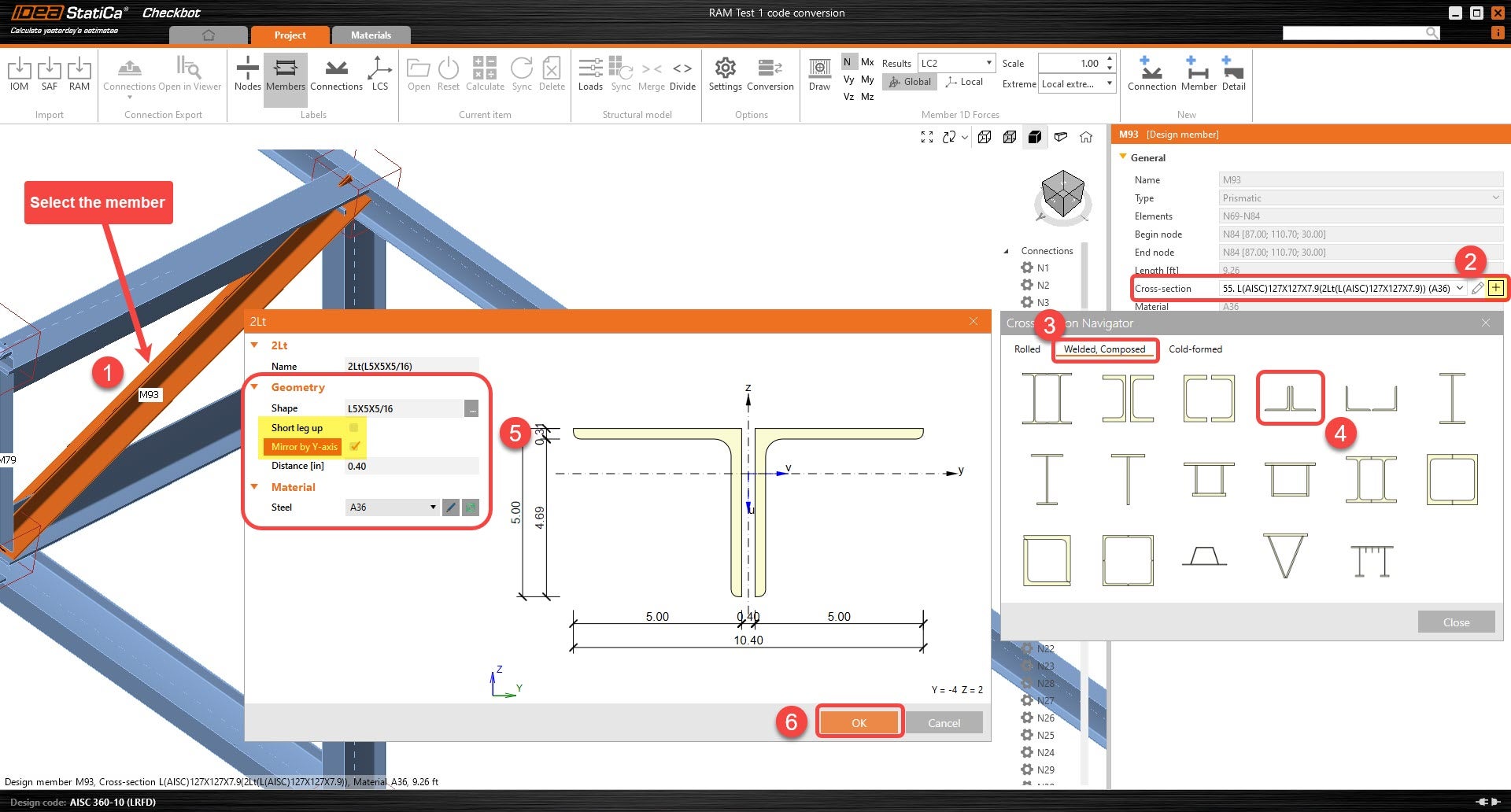
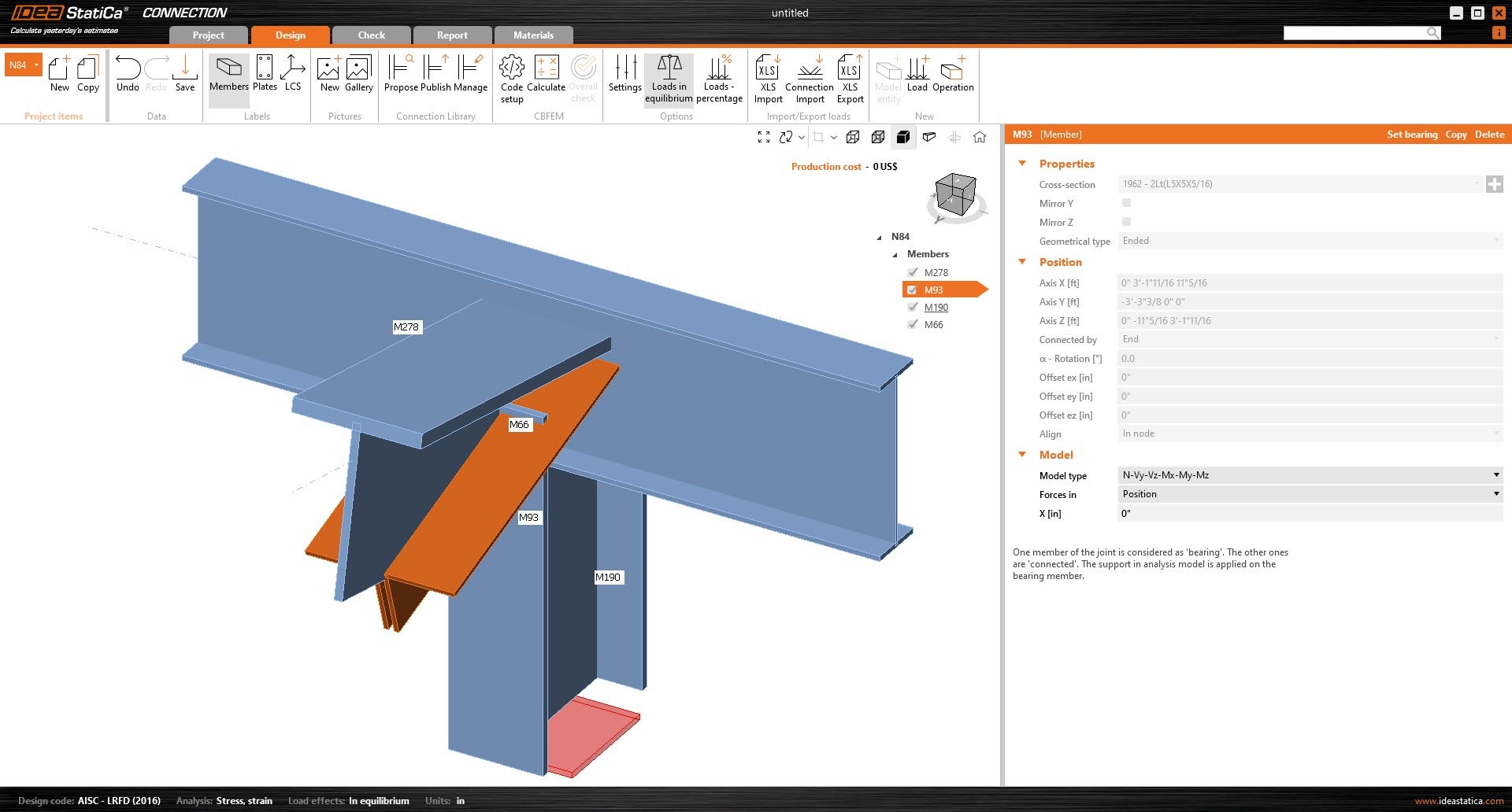
Adjusting non-symmetrical members to correct rotation
6. Select the member that has an incorrect rotation. Under the member's parameter, click on the "+" icon to create a new cross-section. New sections will allow the user to mirror the geometry of the cross-sections by either Y-axis or Z-axis before being applied to the member.
- You can now multi-select multiple members to adjust several at once.
7. Once the connection members are properly rotated, the user can open the connection and start modeling.
Excel template for importing loads
(Only use this template with Checkbot)
Notes: The SAF-based integration is developed and maintained by RISA. IDEA StatiCa is not involved in maintaining this integration. All technical requirements and questions should be addressed to RISA directly.
The following link contains the Load import tool for importing loads:
Workflow:
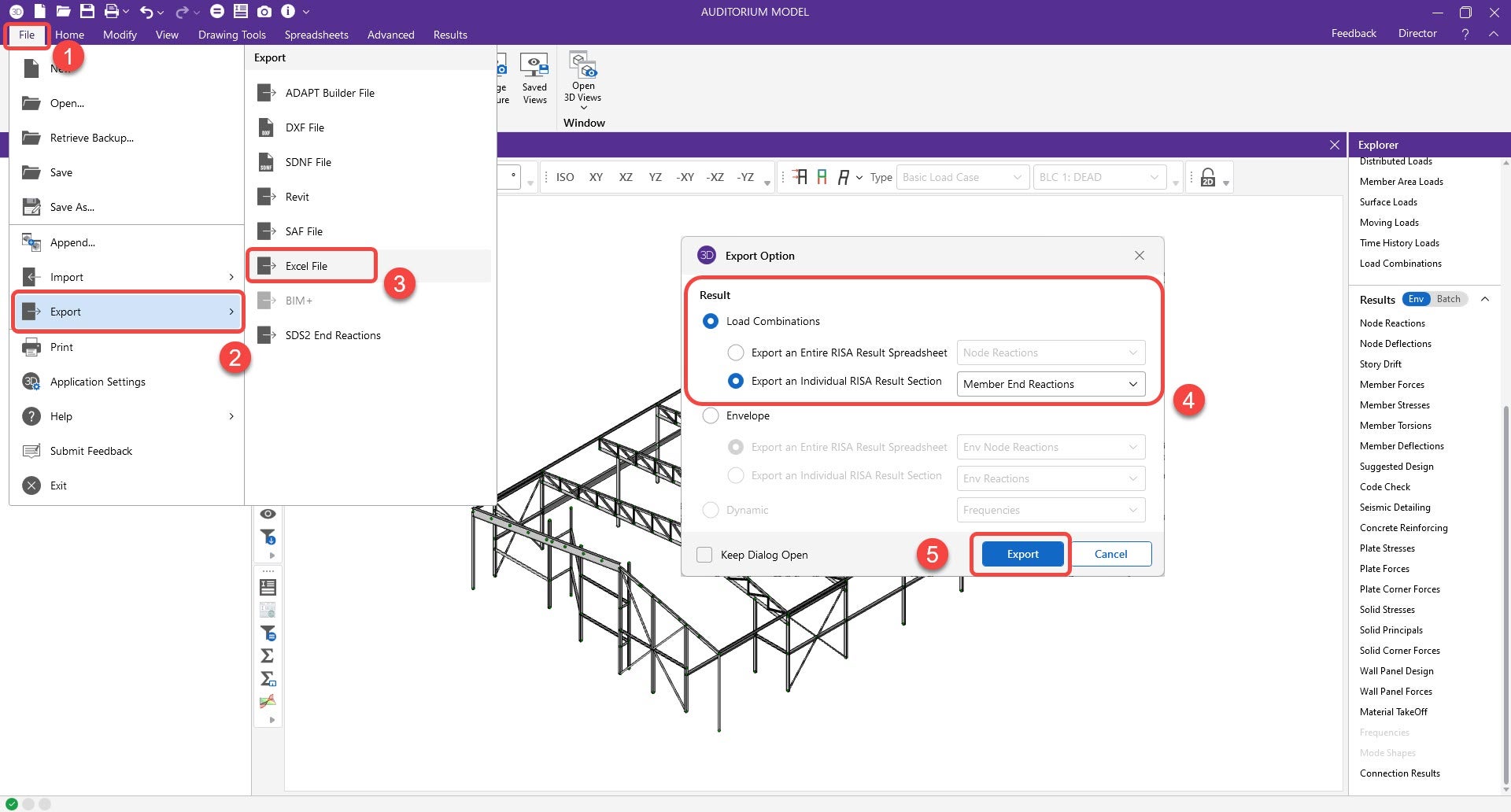
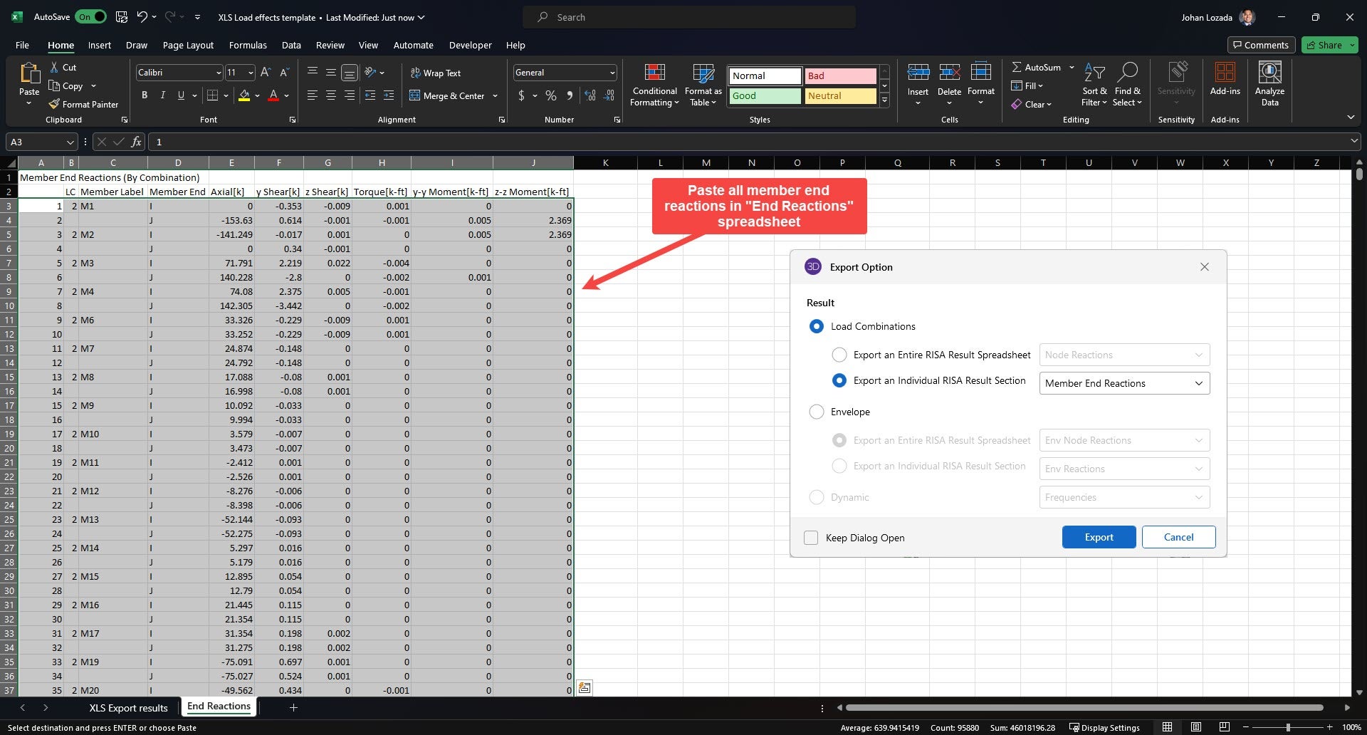
1. Export and save the load results from RISA. Ensure that the load combination results for the member end reactions are exported.
- File --> Export --> Excel file --> Load combinations --> Export an individual RISA Result Section --> Member End Reactions
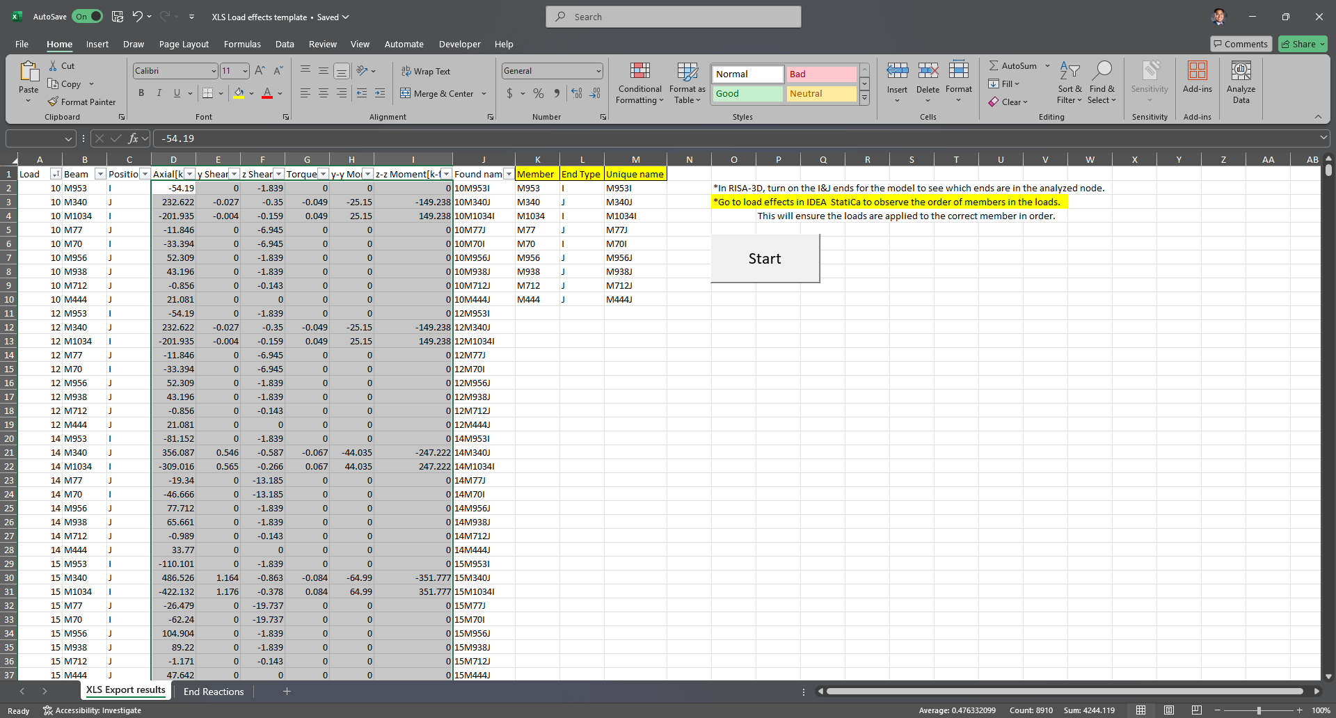
2. Open the Excel file. Select and copy all the member force information from columns A-J.
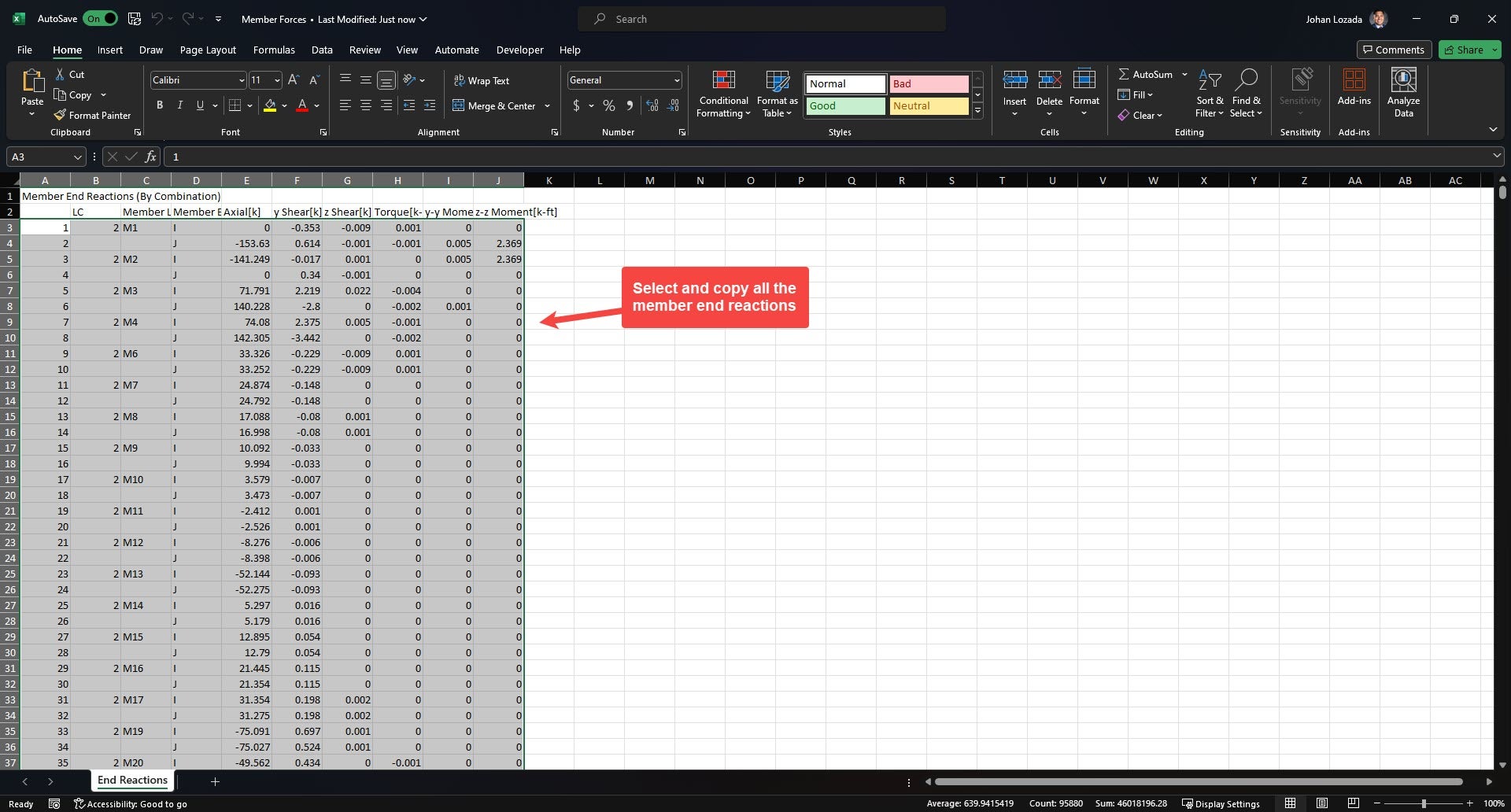
3. Paste the copied information onto the “End Reactions” spreadsheet of the Excel Template.
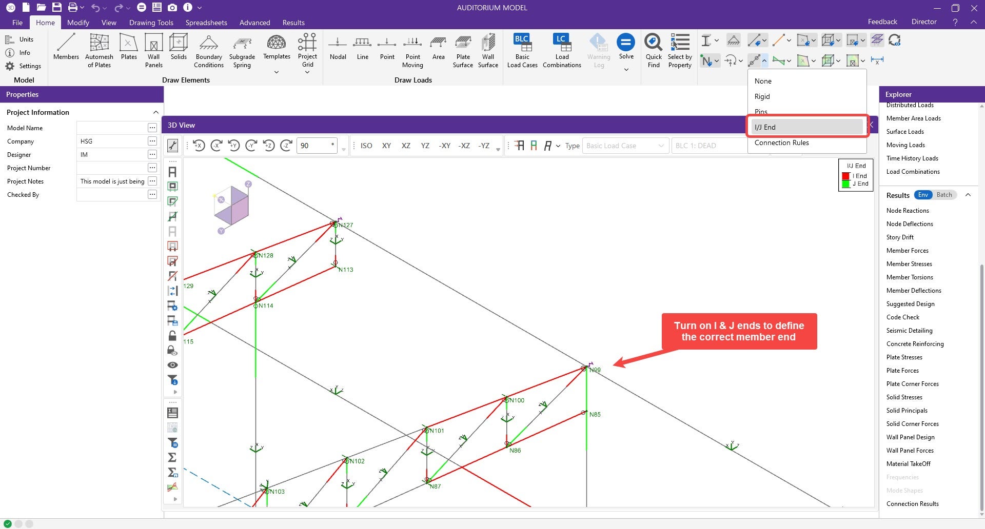
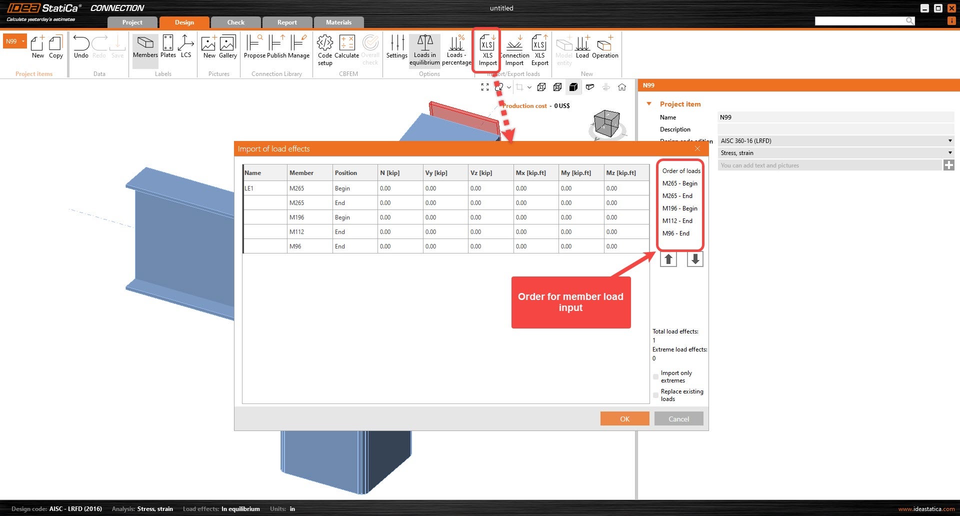
4. Under XLS Export results, Enter the analyzed members in the connection, along with the corresponding end type (I or J end). Ensure that the order of members is the same as the order of IDEA load effects. The I and J ends should also match those from RISA-3D.
Note: IDEA StatiCa member end label will be opposite, "End" -> I-end, "Begin" -> J-end
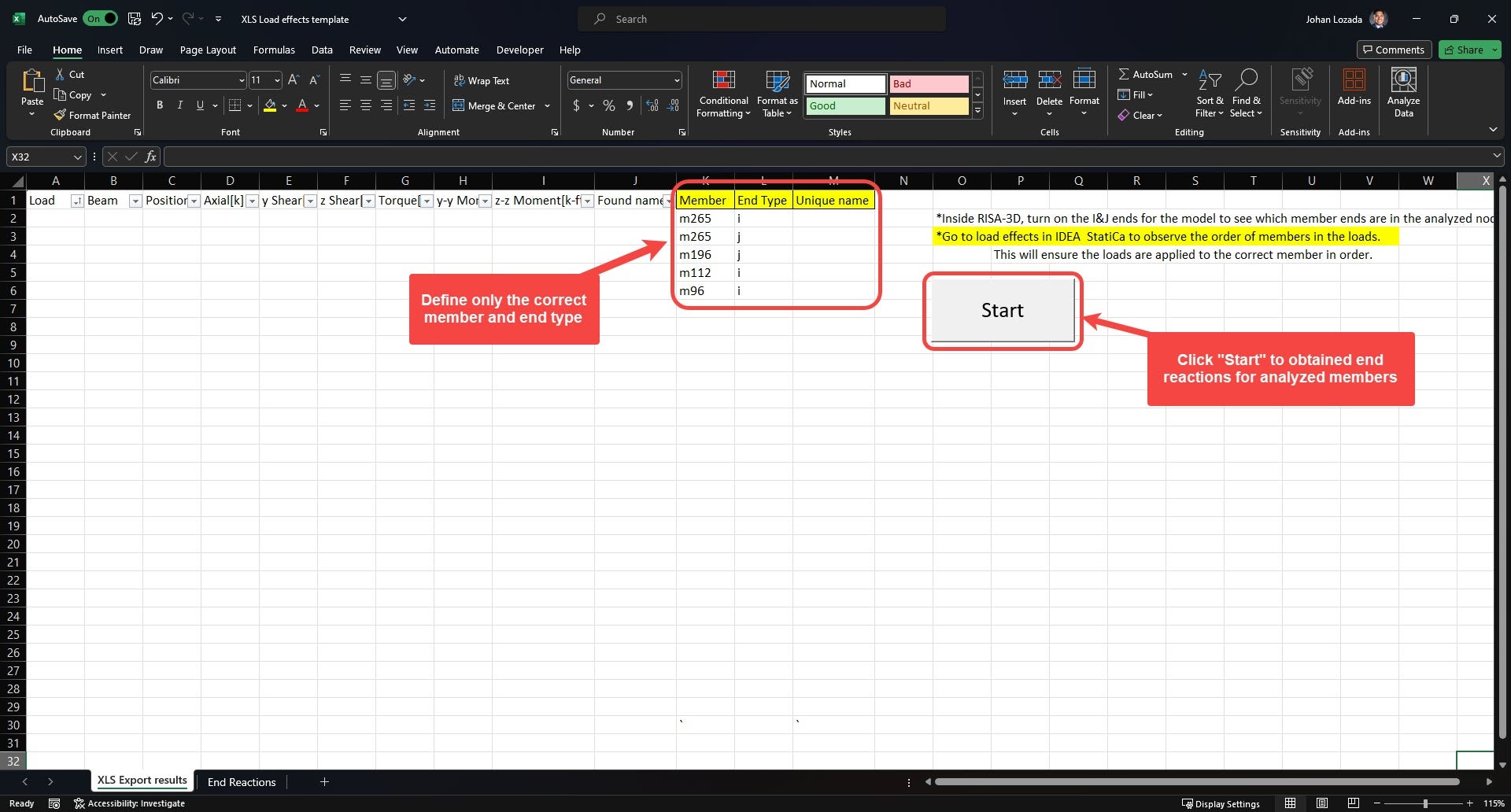
5. Click “start” so that the excel can convert the loads to be imported onto IDEA. Select all the load effects from columns D-I and copy them. (You can copy all loads at once)
6. In IDEA, Under Import/Export loads, select XLS Import. The Import of load effects window will appear. Click under the existing load effect name. It should be the first cell under the “Name” column. Paste the copied load effects, Ctrl+V.
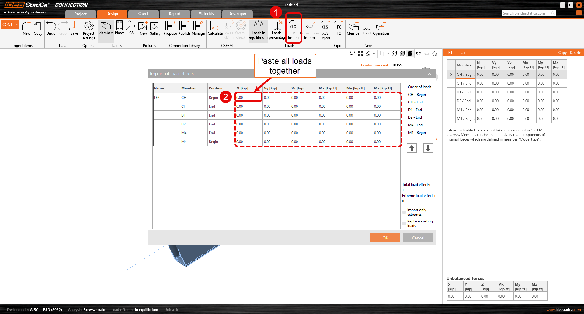
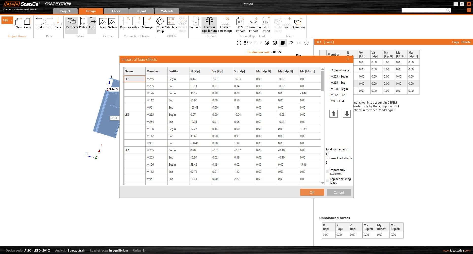
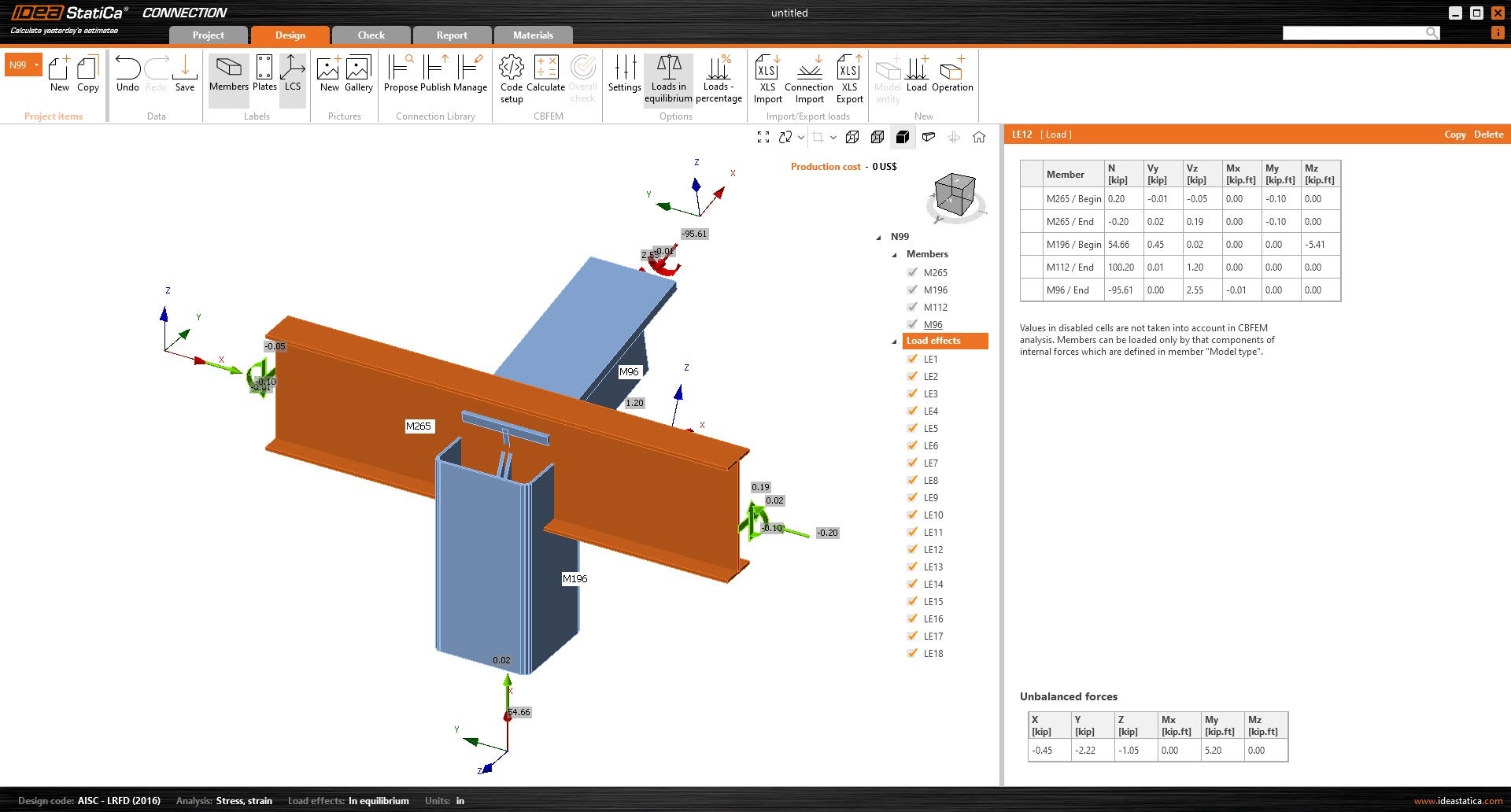
7. Click OK so that the loads can be applied to the connection.
Explanation of differences in LCS and member forces
When working with structural analysis and design software, understanding how local coordinate systems (LCS) are defined is important, especially when transferring member end forces between programs.
In this part, we will compare RISA-3D, a global analysis software, with IDEA StatiCa. While both software packages use a local coordinate system to define member orientation, there are some differences that need attention to ensure accurate force transfer. Below, we will look at the LCS definitions in each software to help you manage these differences and maintain accuracy.
RISA-3D Local Coordinate System:
- X-axis: Along the length of the member.
- Y-axis: Vertical in the plane of the section.
- Z-axis: Perpendicular to both the x and y axes, horizontal in the plane of the section
IDEA StatiCa Local Coordinate System:
- X-axis: Along the length of the member.
- Y-axis: Perpendicular to both the x and z axes, horizontal in the plane of the section
- Z-axis: Vertical in the plane of the section.
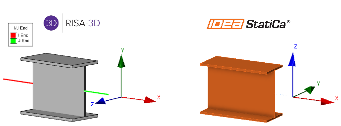
A key difference between the RISA-3D and IDEA StatiCa local coordinate systems (LCS) lies in how the Y and Z axes are defined.
In RISA-3D, the Y-axis is vertical within the plane of the section, while the Z-axis is horizontal. However, in IDEA StatiCa, this is reversed: the Z-axis is vertical, and the Y-axis is horizontal. The X-axis remains consistent in both programs, running along the length of the member.
The difference in axis orientation is important to recognize when transferring end forces between the two programs, as it directly affects the interpretation of force directions.
RISA-3D Member forces:
This diagram shows a member section location with all positive section forces In RISA-3D. The member force results follow the right-hand rule joint convention, consistent with IDEA StatiCa. However, the section forces for RISA shown for any location along the member represent the forces acting on the left side of that section.
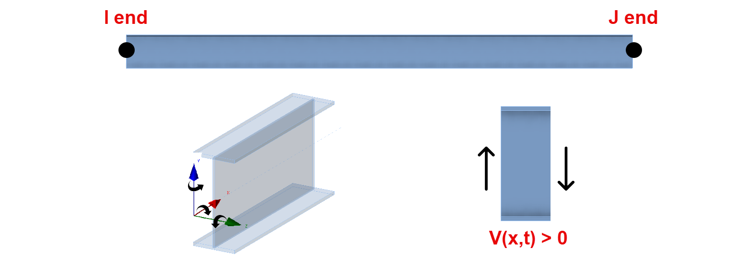
- For axial forces, compression is positive.
- For moments, counterclockwise around the member axis is positive.
- Shear is positive when the free body diagram causes the member to spin clockwise (with I End on the left and J End on the right).
- RISA online help offers the full description for their member force results.
Understanding Forces in RISA-3D and IDEA StatiCa
While RISA only provides left side forces, IDEA uses both left side (J-ends) and right side (I-ends) forces. Using the above information about both IDEA StatiCa and RISA-3D, the following adjustments are made:
I-end:
| XI=-XR | MxI=-MxR |
| VyI=VzR | MyI=MzR |
| VzI=-VyR | MzI=-MyR |
J-end:
| XI=XR | MxI=MxR |
| VyI=-VzR | MyI=-MzR |
| VzI=VyR | MzI=MyR |
Note: RISA-3D’s SAF file export currently includes only cross-section and geometry data, not load effects, which is why this document is important. When transferring forces from RISA-3D to IDEA StatiCa, understanding the alignment of each software’s coordinate system is crucial. For more accurate force transfer, consider contacting RISA to request the inclusion of load effects in future SAF file exports.