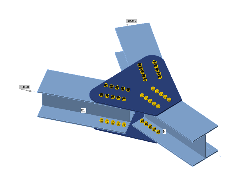
Code-check of bolts and preloaded bolts according to Australian standards
The forces in bolts including prying forces are determined by finite element analysis. The bolt resistances are checked by code provisions.
Bolts
Bolts are checked according to Chapter 9.2 Design of bolts. The tensile and shear force in each bolt is determined by finite element analysis. Prying forces are taken into account as suggested by Clause 9.1.8. Prying forces are determined by finite element analysis. Each shear plane is checked individually. Ply in the bearing is checked against the sum of shear forces at nearby planes.
Bolt in shear
A bolt subject to a design shear force is designed according to Cl. 9.2.2.1 and shall satisfy:
\[ V_f^* \le \phi V_f \]
where:
- Vf* – design shear force
- ϕ = 0.8 – capacity factor (Table 3.4) editable in Code setup
- Vf = 0.62 fuf A – nominal shear capacity of a bolt
- fuf – minimum tensile strength of the bolt as specified in Table 9.2.1
- A – area of a bolt equal either to Ac or Ao which are minor diameter area of the bolt as defined in AS 1275 or nominal plain shank area of the bolt, respectively. Each shear plane is checked individually.
The value of Ac is in the software approximated by a function:
Ac = 0.0000163 · As2 + 0.91682 · As − 0.85375
The maximal difference is 0.8 mm2 or 0.5 %.
Reduction factor given in Table 9.2.2.1 to account for the length of a bolted lap connection equals 1.0. The reduction is applied automatically by checking each bolt individually.
According to Cl. 9.2.2.5, for connections in which filler plates exceed 6 mm in thickness, the nominal shear capacity of a bolt shall be reduced by 15 %. For multi-shear plane connection, the reduction is applied to all shear planes.
Bolt in tension
A bolt subject to design tension force is designed according to Cl. 9.2.2.2 and shall satisfy:
\[ N_{tf}^* \le \phi N_{tf} \]
where:
- Ntf* – design tension force
- ϕ = 0.8 – capacity factor (Table 3.4) editable in Code setup
- Ntf = As fuf – nominal tensile capacity of a bolt
- As – tensile stress area of a bolt as specified in AS 1275
- fuf – minimum tensile strength of the bolt as specified in Table 9.2.1
Bolt subject to combined shear and tension
A bolt required to resist both design shear and design tensile forces at the same time is designed according to Cl. 9.2.2.3 shall satisfy:
\[ \left ( \frac{V_f^*}{\phi V_f} \right ) ^2 + \left ( \frac{N_{tf}^*}{\phi N_{tf}} \right ) ^2 \le 1.0 \]
where:
- ϕ = 0.8 – capacity factor (Table 3.4) editable in Code setup
Ply in bearing
A ply subject to a design bearing force due to a bolt in shear is designed according to Cl. 9.2.2.4 and shall satisfy:
\[ V_b^* \le ϕ V_b \]
where:
- ϕ = 0.9 – capacity factor (Table 3.4) editable in Code setup
- \( V_b = 3.2 d_f t_p f_{up} \le a_e t_p f_{up} \) – nominal bearing of a ply
- df – diameter of a bolt
- tp – thickness of the ply
- fup – tensile strength of the ply
- ae – minimum distance from the edge of a hole to the edge of a ply, measured in the direction of the component of a force, plus half the bolt diameter. The edge of a ply shall be deemed to include the edge of an adjacent bolt hole
Friction-type connections
For friction-type connections, the slip in serviceability limit state is required to be limited and designed according to Cl. 9.2.3. These bolts should be also checked as bearing type for ultimate limit state. A bolt subjected to shear force shall satisfy:
\[ V_{sf}^* \le ϕ V_{sf} \]
where:
- ϕ = 0.7 – capacity factor (Chapter 3.5.5) editable in Code setup
- Vsf = μ Nti kh – nominal shear capacity of a bolt
- μ = 0.35 – slip factor as specified in Clause 9.2.3.2 editable in Code setup
- Nti – minimum bolt tension at installation as specified in Clause 15.2.2.2
| Nominal diameter of bolt | Minimum bolt pretension [kN] |
| M16 | 95 |
| M20 | 145 |
| M24 | 210 |
| M30 | 335 |
| M36 | 490 |
| Other | \(A_s \cdot 600\) MPa |
- k h – factor for different hole types, as specified in Clauses 9.2.3.1 and 14.3.2
- k h = 1 for standard holes (+2 mm for d f ≤ 24 mm, +3 mm otherwise)
- k h = 0.85 for short slotted (hole length ≤ max(1.33 d f, d f + 10 mm)) and oversize holes
- k h = 0.70 for long slotted holes
Number of effective interfaces, nei, is always equal to 1, because each interface is checked separately.
Bolts in a friction-type connections loaded by combined shear and tension should satisfy:
\[ \left ( \frac{V_{sf}^*}{ϕ V_{sf}} \right ) + \left ( \frac{N_{tf}^*}{ϕ N_{tf}} \right ) \le 1.0 \]
where:
- Vsf* – design shear force on the bolt in the plane of the interfaces
- Ntf* – design tensile force on the bolt
- ϕ = 0.7 – capacity factor (Chapter 3.5.5) editable in Code setup
- Vsf – nominal shear capacity of the bolt
- Ntf = Nti – nominal tensile capacity of the bolt equal to minimum bolt tension at installation
Friction-type connections should be also checked for ultimate limit state. The bolt type should be changed to bearing – tension/shear interaction, the loads increased appropriately and the joint should be checked again.


