Lateral stability for concrete beams – all inputs and outputs, analysis, and known limitations
In IDEA StatiCa Beam, in addition to the simplified lateral stability assessment according to EN 1992-1-1 Cl. 5.9, a sophisticated materially and geometrically non-linear analysis can be performed to determine the design internal forces for several design situations – lifting, transport, final support, and end of design life. However, this type of analysis requires a significant amount of input, which we will explain in the following article.
Model preparation
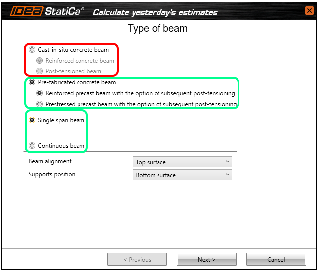
First of all, we will see for which types of beams this advanced analysis can be performed. When you start a new project, you are always asked what type of beam you intend to model. Figure 1 is an introductory wizard where it shows in red (not supported) and green (supported) which beams the analysis is supported for.
\[ \textsf{\textit{\footnotesize{Fig. 1\qquad Supported and not-supported types of beam for advanced lateral stability analysis}}}\]
It follows, therefore, that all precast beams are supported, which may be single-span or multiple-span. For multi-span models, you will analyze each prefabricated beam separately for all construction stages before casting the top slab.
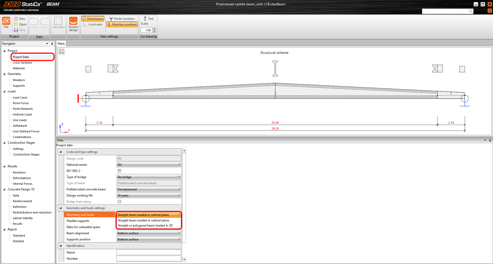
After creating the beam, you can change the type of the Prefabricated concrete beam in the Project data section (the Beam type itself cannot be changed). An important setting here is Geometry and loads, where you can decide whether to model a Straight beam loaded in vertical plane or a Straight or polygonal beam loaded in 3D.
\[ \textsf{\textit{\footnotesize{Fig. 2\qquad Project data – activation of loading in 3D allowing input of eccentricity}}}\]
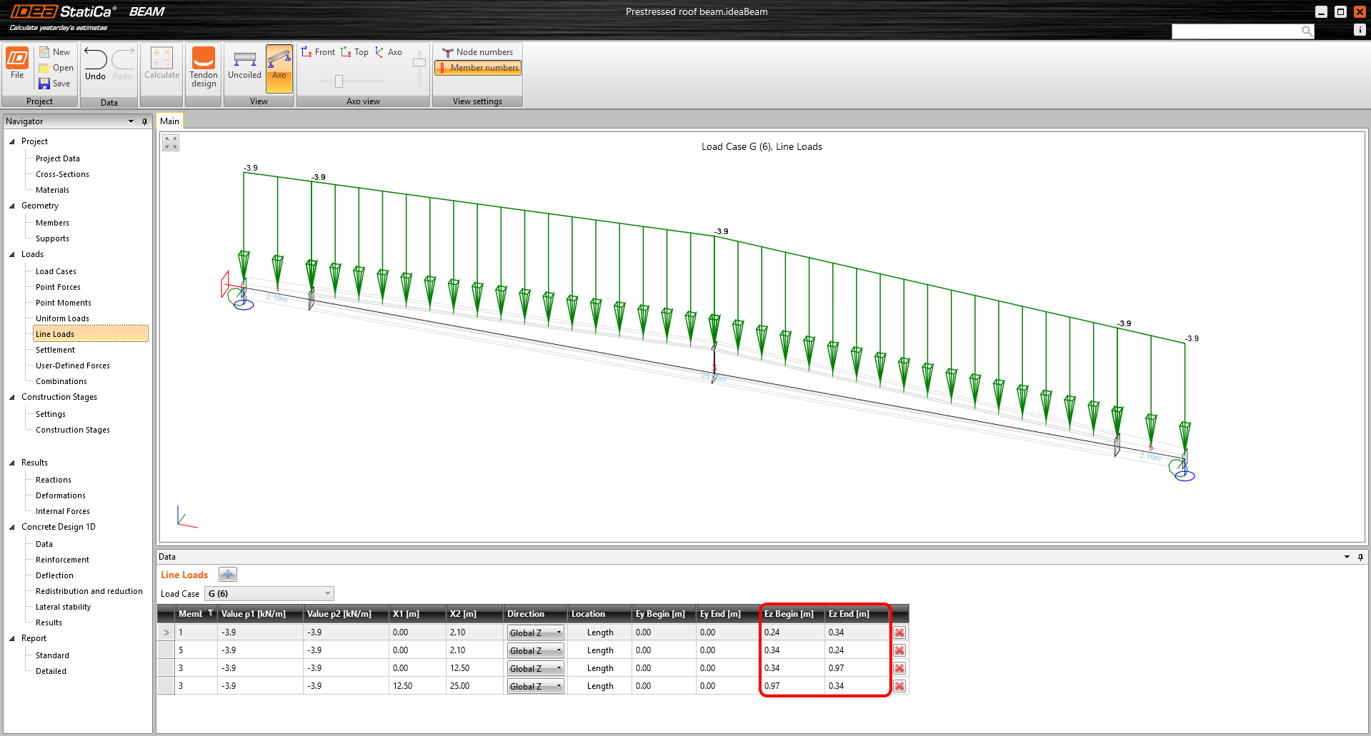
If you do not choose the 3D option, you will not be able to enter loads with horizontal and vertical eccentricity, which is essential for stability loss assessments.
\[ \textsf{\textit{\footnotesize{Fig. 3\qquad Example of specifying a linear load on the top surface of a beam}}}\]
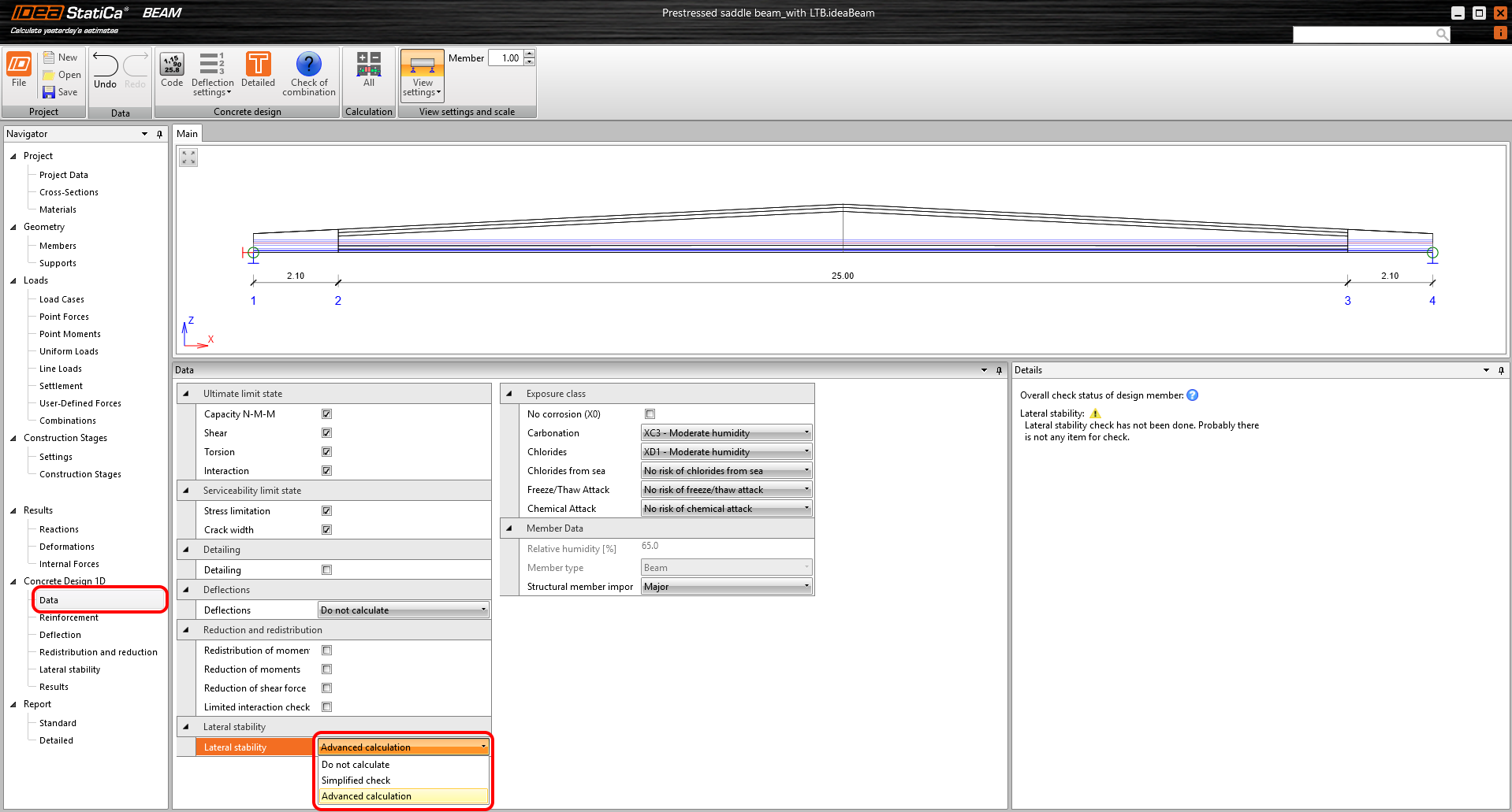
After you have finished modeling the geometry, prestressing, reinforcement, and loading in the application, you can calculate the model and proceed to the actual checks. The first step is to choose what you want to assess. This is done in the Concrete Design 1D – Data section. Here, you can also choose if you want to do a lateral stability check and what type of calculation will be used – simplified according to EN 1992-1-1 Cl. 5.9 or advanced.
\[ \textsf{\textit{\footnotesize{Fig. 4\qquad Turning on the advanced lateral stability analysis}}}\]
Inputs – Data
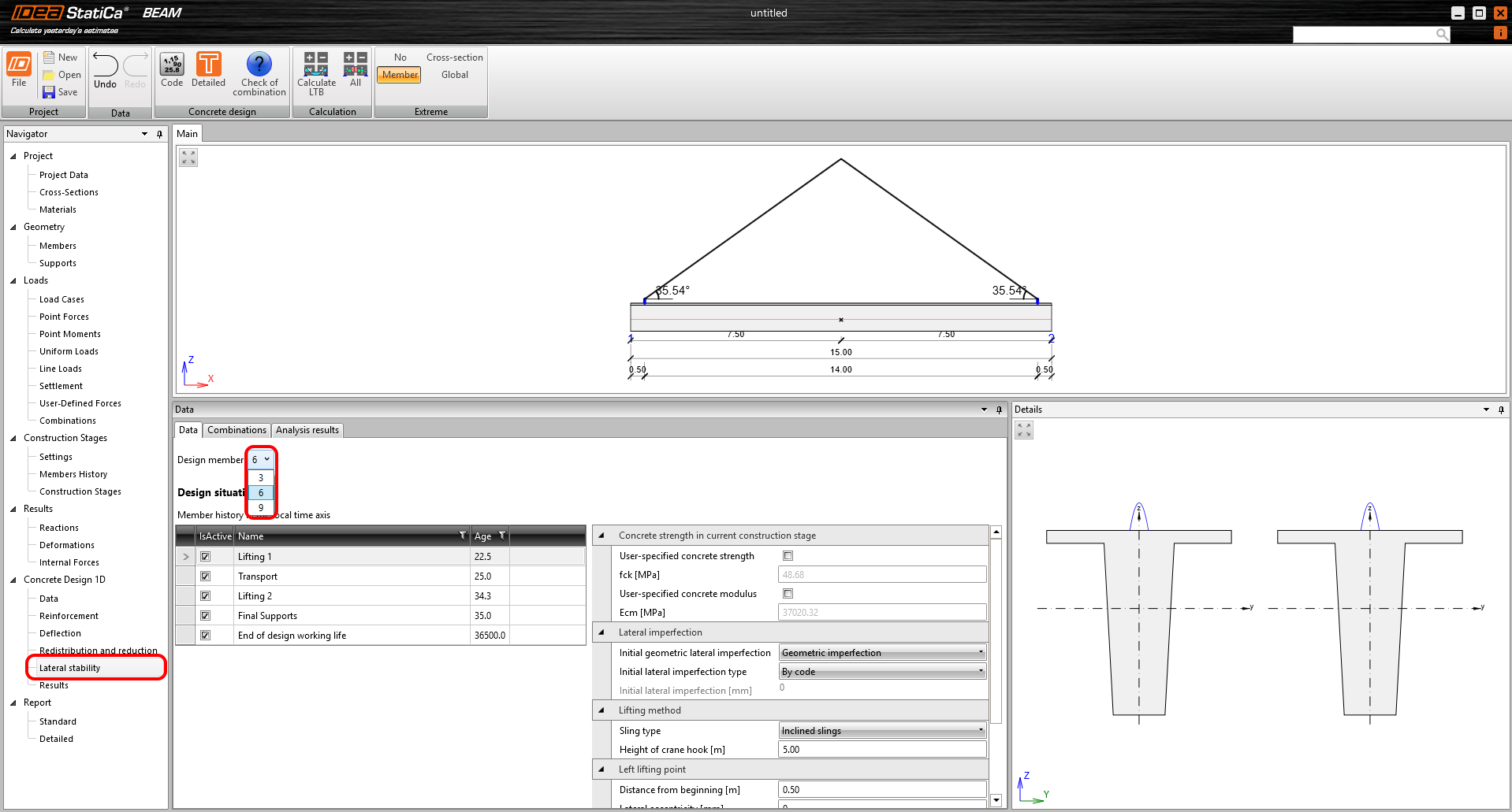
As already mentioned, for multi-span modules, each precast beam can be evaluated independently. You can switch between beams using the Design member drop-down menu.
\[ \textsf{\textit{\footnotesize{Fig. 5\qquad Selection of the design member from the list of prefabricated beams}}}\]
You can perform advanced material and geometric non-linear analysis for a total of five design situations at various times:
- Lifting 1
- Transport
- Lifting 2
- Final supports
- End of design working life – not available for composite beams
These design situations are independent of the construction stages for TDA. In other words, TDA and lateral stability are calculated independently.
For each design situation, the age from which fck and Ecm are calculated is entered. Alternatively, both values can be defined by a user-defined value, for example, according to the test results of the concrete used.
\[ \textsf{\textit{\footnotesize{Fig. 6\qquad Input of age, concrete strength, and modulus of elasticity}}}\]
Keep in mind that the design stress-strain diagram for concrete is used for ULS calculations and is based only on the concrete compressive strength fck. Therefore, the change in Ecm will not be reflected in these calculations.
Another common input for all design situations is initial lateral imperfection. Here, we have several options:
- Geometric imperfection – rheology strain is automatically added as a load
- By code – imperfection is assumed according to EN 1992-1-1, chap. 5.9 (2), as L/300
- User-defined – direct input of a value
- Overall imperfection – input value is Geometric imperfection + rheology strain
- User-defined – direct input of a value
The difference between Geometric and Overall imperfection is that the strain from shrinkage calculated from beam fabrication to the time set for individual design situations is automatically added to the geometric imperfection. On the other hand, the value of the Overall imperfection is taken into the calculation directly without further adjustments.
Lifting
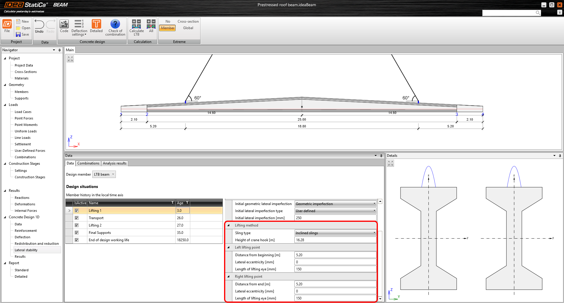
There are two design situations dedicated to lifting, which are identical in terms of inputs and calculation. The user has a choice of two lifting methods:
- Inclined slings
- Vertical slings
For both, it is possible to set the Length of lifting eye, which controls the vertical distance of the lifting point (center of rotation) from the top surface of the beam. The lifting point is the point at which the flexible support joins the rigid body. A line passing through the lifting point at each support forms a roll axis. Horizontal distances can also be set using Lateral eccentricity and Distance from end. Both lifting points can be set independently (asymmetrically), so it is possible that the roll axis will not be parallel to the beam's axis.
For inclined slings, it is also necessary to specify the Height of the crane hook used to define the lifting angles and the additional normal force from the sling.
\[ \textsf{\textit{\footnotesize{Fig. 7\qquad Example of input for a lifting design situation}}}\]
For more theory about lifting and to be sure the calculation is correct, you can check the following verification article, Lateral stability of long prestressed concrete beams during lifting
Transport
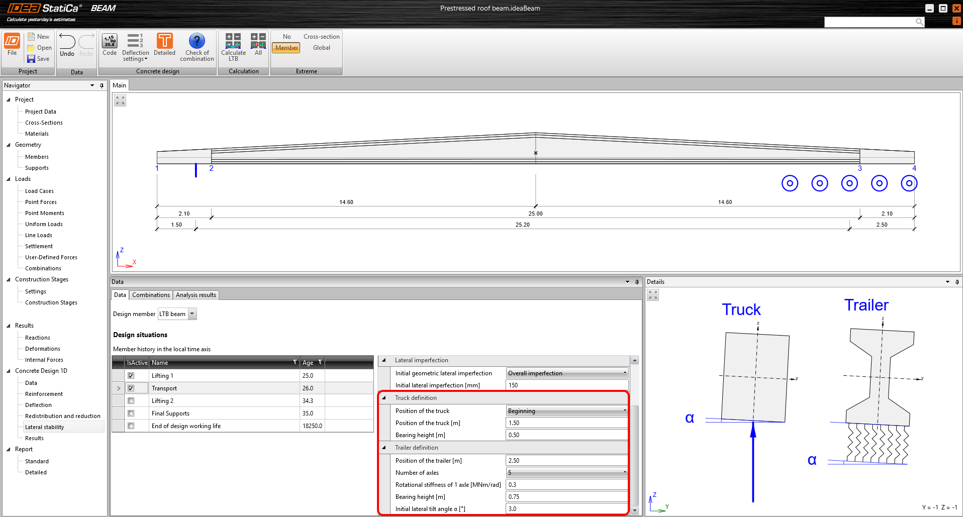
The beam is transported in such a way that one end of it lies on the truck and the other on the trailer. In terms of calculation, this means that one side (truck side) is supported by a perfect hinge – free to roll – and the other (trailer side) is supported by a hinge with defined rotational stiffness about x axes.
Truck
Of course, you can enter the Position of the truck to define the distance from the end of the beam. In addition, you can also specify the Bearing height, which is the vertical distance of the roll axis from the bottom surface of the beam.
Trailer
Trailer support is also point support (but with a defined rotational stiffness). Position of the trailer defines the distance of the support from the end of the beam and Bearing height again defines the distance of the roll axis from the bottom surface of the beam. The rotational stiffness of the trailer support is defined by the stiffness of the axles themselves, where the total stiffness of the trailer support is the Number of axles times the Rotational stiffness of 1 axle.
Recommended values for the axle stiffness are defined, for example, in [2] - 340 to 680 kNm/rad per dual-tire axle. The higher values apply to rigs without leaf springs, in which the spring is primarily in the tires. For a single axle, the half value can be taken into account.
The last input is the Initial lateral tilt angle α. This expresses the road tilt. The standard roadway tilt is approximately 1.5°, with the possibility of up to 5° in curves on standard roads.
\[ \textsf{\textit{\footnotesize{Fig. 8\qquad Example of input for a transport design situation}}}\]
Final supports
For this design situation, the user has a choice of three types of support:
- Elastomeric bearing
- Fork
- Bearing pad with dowel
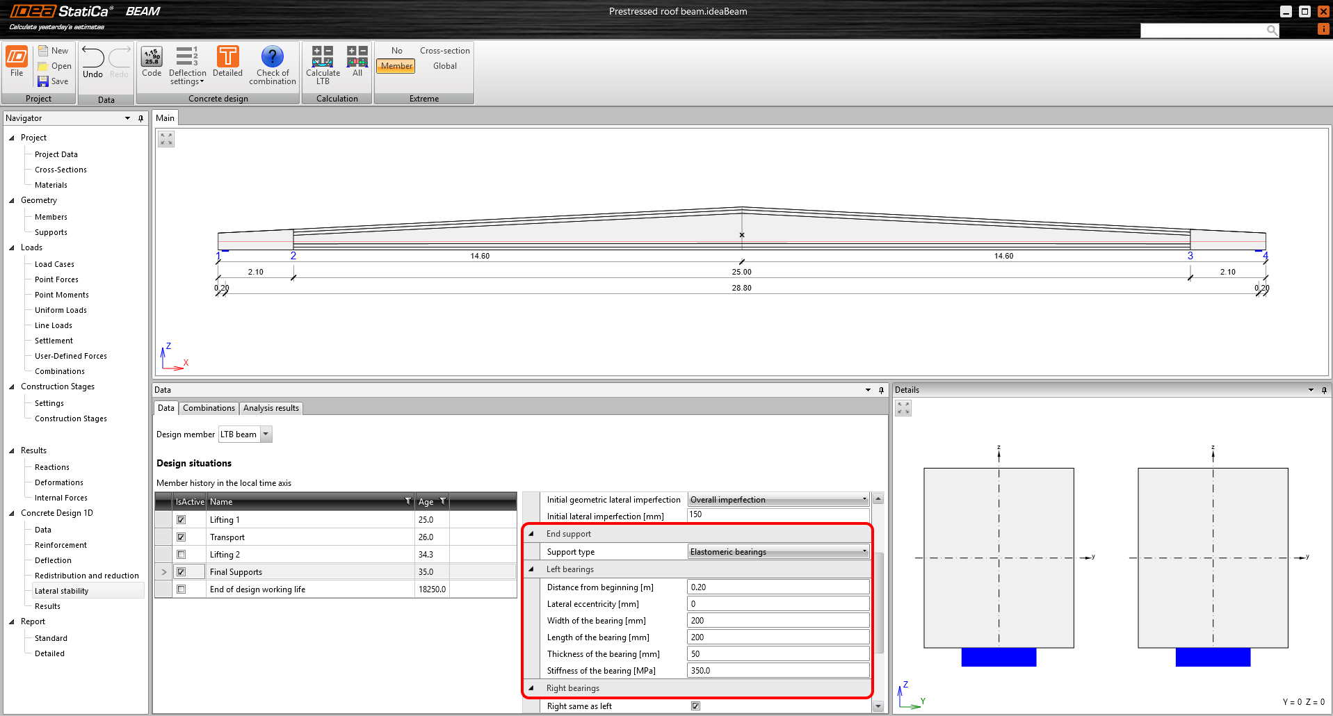
Elastomeric bearing
Here, it is necessary to define the geometry of the supports in terms of distance from the beginning and end of the beam, lateral eccentricity, and the bearing dimensions themselves. Next, the Stiffness of the bearing in MPa is entered, which is basically the modulus of elasticity of the bearing material that must be read from the manufacturer's technical sheet. The stiffness of the supports in all three directions, including the rotational stiffness, is then calculated from the bearing dimensions and the modulus of elasticity of the material. The left and right bearings can be specified independently, so the roll axis again does not have to be parallel to the beam axis.
\[ \textsf{\textit{\footnotesize{Fig. 9\qquad Example of input for a final supports design situation – elastomeric bearings}}}\]
Fork and Bearing pad with dowel
In terms of the model, the two types are identical. A support is placed on the bottom surface of the end of the beam which is rotationally rigid about the x-axis. However, it is possible to specify a user-defined rotational stiffness in MNm/rad.
Another feature of these types of supports is the ability to insert intermediate supports into the model, where their number and possibly axial stiffness (rigid by default) are defined.
\[ \textsf{\textit{\footnotesize{Fig. 10\qquad Example of input for a final supports design situation – Bearing pad with dowel with intermediate supports}}}\]
End of design working life
The settings for the last design situation are taken from the Final Supports. This means that a model is calculated where only the age-dependent characteristics are different.
Inputs – Combinations
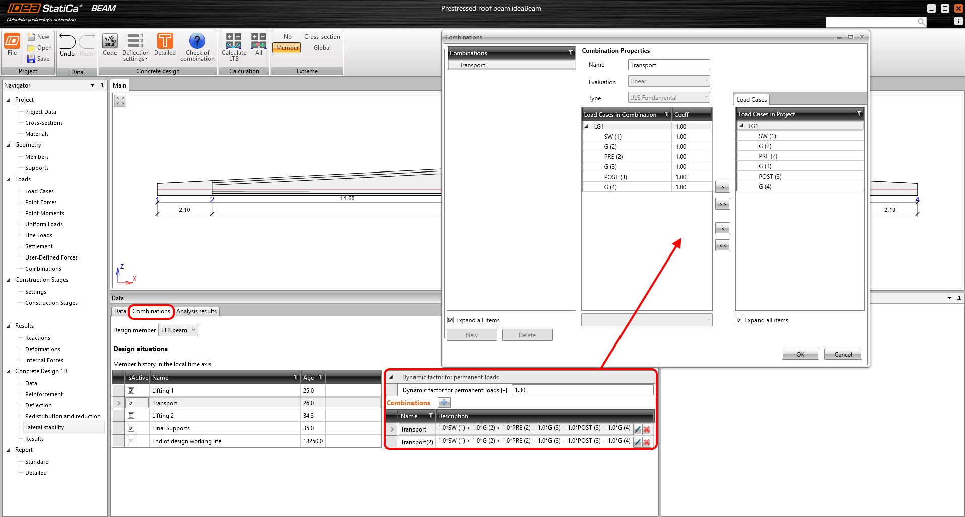
In the Combinations tab, the user can enter any number of combinations in the same way that combinations are entered for the basic calculation in the application. The load cases relevant to the individual design situations are always available. However, there are some limitations.
- Lifting can only be done with self-weight and prestressing
- Variable load cases can only be included in the End of design working life
- Additional loads can be added to the Transport and Final supports design situation by inserting them into the predefined permanent load cases, referred to as G in the application
- In the current version, only ULS combinations are supported
\[ \textsf{\textit{\footnotesize{Fig. 11\qquad Specifying combinations and the dynamic factor}}}\]
Last but not least, a dynamic factor for permanent loads is added to the combinations for lifting and transport. To give you an idea, here is a table of recommended values. However, the national standards and values recommended for the anchors used must always be followed.
\[ \textsf{\textit{\footnotesize{Fig. 12\qquad Recommended dynamic factors}}}\]
Analysis and results
As already mentioned, it is a fully materially and geometrically nonlinear analysis. Both concrete and prestressing reinforcement are considered in the model. The tensioned concrete is automatically excluded from the calculation, i.e., the cross-sectional characteristics are adjusted during the calculation according to the actual cracking.
Supports
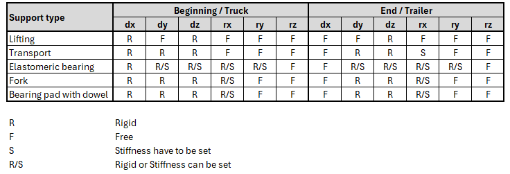
Much has been written in this article about how the model is supported for different design situations and where to set the support stiffness. Let's close this topic with a summary table for all support types.
\[ \textsf{\textit{\footnotesize{Fig. 13\qquad Supports for all types of model}}}\]
Note: Some models would be singular with the supports listed. However, there are some measures introduced in the solver itself to ensure convergent computation.
Material models for ULS
Concrete material model
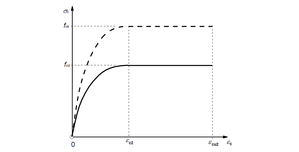
The parabola-rectangle diagram for concrete under compression according to EN 1992-1-1 3.1.7 (1) is used for the structural model as well as for the RCS assessments. For ULS, concrete in tension is always excluded.
\[ \textsf{\textit{\footnotesize{Fig. 14\qquad Parabola-rectangle diagram for concrete under compression}}}\]
The design stress-strain diagram is based only on the concrete compressive strength fck. Therefore, the change in Ecm will not be reflected in ULS calculations.
Reinforcement material model
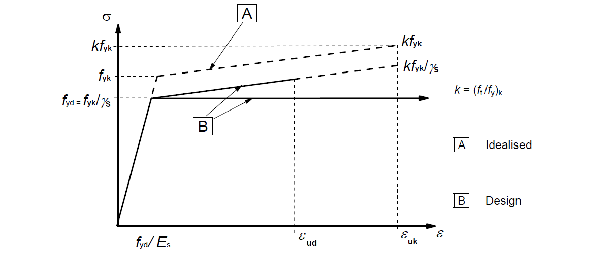
For reinforcement steel, the stress-strain diagram according to EN 1992-1-1 Cl.3.2.7 (2) is used. The user can choose whether a diagram with a horizontal or inclined top branch is used.
\[ \textsf{\textit{\footnotesize{Fig. 15\qquad Idealized and design stress-strain diagrams for reinforcing steel (for tension and compression)}}}\]
Prestressing material model
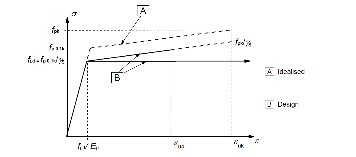
For prestressing steel, the stress-strain diagram according to EN 1992-1-1 Cl.3.2.6 (7) is used. The user can choose whether a diagram with a horizontal or inclined top branch is used.
\[ \textsf{\textit{\footnotesize{Fig. 16\qquad Idealized and design stress-strain diagrams for prestressing steel (absolute values are shown for tensile stress and strain)}}}\]
Stress in prestressing strands and tendons
The tension is applied to the prestressing strands and tendons with a value calculated from the TDA (Time Dependent Analysis), according to the age specified for each design situation. However, keep in mind that the model for the lateral stability calculation and the model for the basic calculations in the IDEA StatiCa Beam application are different, so there may be slight differences in the calculated internal forces.
Analysis results
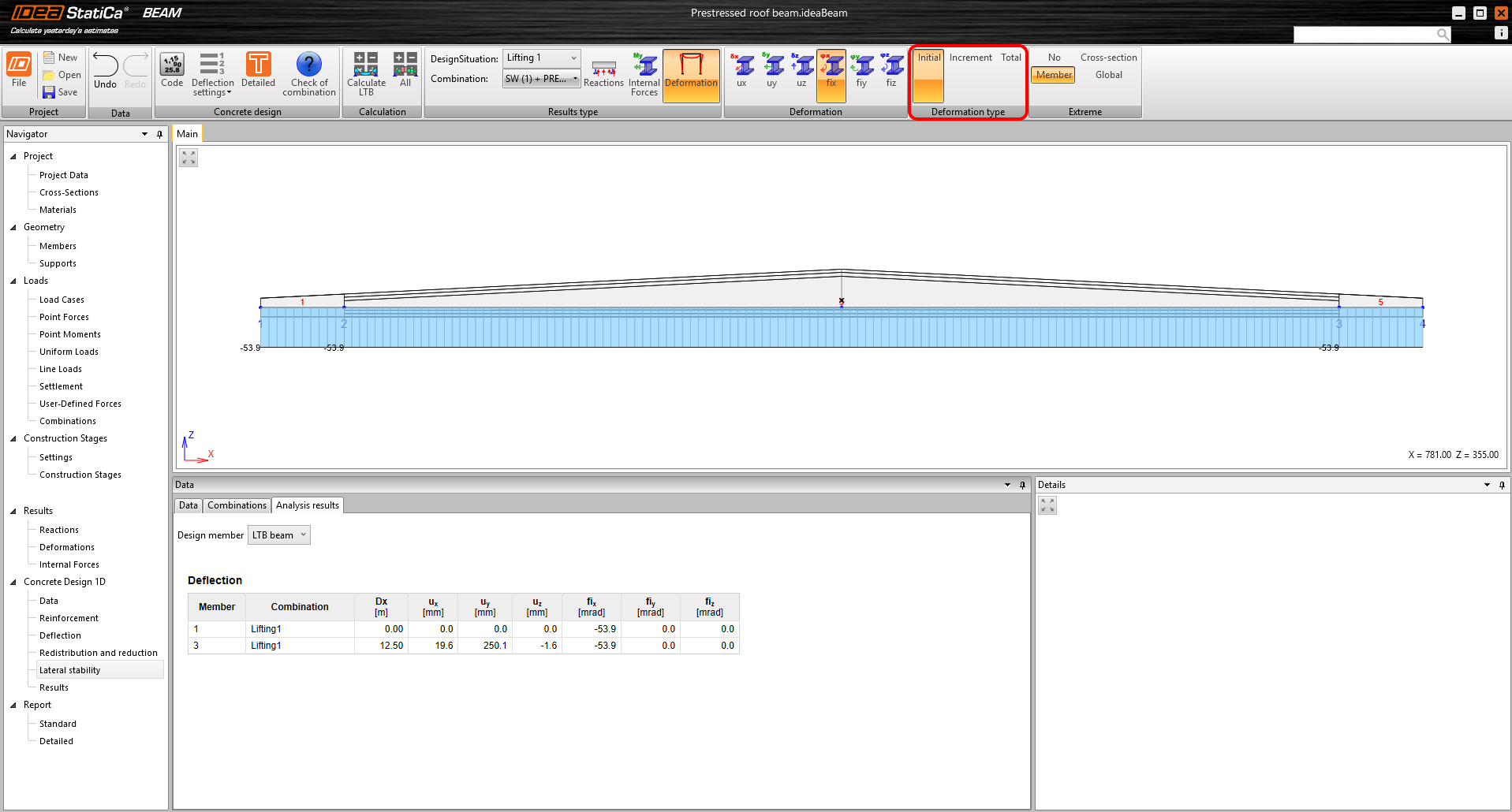
In the Analysis results tab, you can get two types of results. The first is the warning status – The calculation stopped, because of divergence of non-linear calculation. This means that the beam has failed to lose stability. The second type of result is a set of reactions, internal force, and deformation. All of them can be shown for each design situation and combination. The results are always displayed to the beam centerline (center of gravity axis). It is worth explaining the Deformation type toolbar, where the user can view three types of deformations:
- Initial
- Increment
- Total
\[ \textsf{\textit{\footnotesize{Fig. 17\qquad Selection of the Deformation type}}}\]
For a full understanding, it is first necessary to look at how models are built for each design situation.
Let's start by lifting.
- The beam is deformed into a parabolic shape by the value of the initial imperfection
- It is then mounted on hinges. This causes an initial rotation so that the center of gravity is below the roll axis – Initial deformation
- Loads are applied (including proportional distortions from shrinkage). A non-linear calculation is run to determine the additional rotation and deformation – Increment of deformation
This implies that the initial deformation is read after the beam is suspended, when the initial rotation took place, but before the actual nonlinear calculation. The increment is the deformation that results from the non-linear calculation with all loads and the total is the sum of the first two.
For the Transport, the situation is very similar: First, the deformed beam with the initial imperfection is rotated by the α angle, and placed on the supports (defined in the article above). Here the initial deformation is read. Then a non-linear calculation is run with the applied load (including shrinkage if the user specifies Geometric Imperfection, see above). The deformation as a result of the nonlinear calculation is again displayed as an increment. Total is the sum of Initial and Increment.
The procedure is the same for Final supports and End of design working life.
Known limitations
The current version of the program is limited as follows.
- Only ULS calculations are available.
- Automatic calculation of creep has not been implemented yet.
- Direct connection to the cross-sectional check application has not yet been implemented
All mentioned features are currently under development and will be added in upcoming versions.
References
[1] Mast, R. F. (1989). “Lateral Stability of Long Prestressed Concrete Beams, Part 1.” PCI J. 34(1), 34–53.
[2] Mast, R. F. (1993). “Lateral Stability of Long Prestressed Concrete Beams, Part 2.” PCI J., 38(1), 70–88.


