
Learning module: Strength Design by Inelastic Analysis
Connection design can be difficult to teach, given the detailed nature of the topic and the fundamentally three-dimensional behavior of most connections. However, connections are critically important, and lessons learned in the study of connection design, including load path and identification and evaluation of failure modes, are general and applicable to structural design broadly. IDEA StatiCa uses a rigorous nonlinear analysis model and has an easy-to-use interface with a three-dimensional display of results (e.g., deformed shape, stress, plastic strain) and thus is well suited for the exploration of the behavior of structural steel connections. Building on these strengths, a suite of guided exercises that use IDEA StatiCa as a virtual laboratory to help students learn about concepts in structural steel connection behavior and design was developed. These learning modules were primarily targeted to advanced undergraduate and graduate students but were made suitable for practicing engineers as well. The learning modules were developed by Associate Professor Mark D. Denavit from the University of Tennessee, Knoxville.
Learning Objective
After performing this exercise, the learner should be able to interpret key analysis outputs in support of design by inelastic analysis.
Background
The Handbook of Structural Steel Connection Design and Details (Tamboli, 2017) lays out a general procedure for connection design as follows:
- Determine the applied loads and their lines of action.
- Make a preliminary layout, striving to keep the connection as compact as possible.
- Decide on where bolts and welds will be used and select bolt type and size.
- Decide on a load path through the connection.
- Provide sufficient strength, stiffness, and ductility.
- Perform final checks for specification-required spacings and to ensure that the connection can be fabricated and erected.
This procedure applies to traditional connection design as well as connection design by inelastic analysis. The differences between these two approaches are primarily in how steps 4 and 5 are accomplished.
“Deciding” on a load path means making use of the lower bound theorem of limit analysis. This theorem states that any load path that satisfies equilibrium and the limit states yields a safe connection. For a statically determinate connection, only one load path will satisfy equilibrium. For a statically indeterminate connection, many possible load paths can satisfy equilibrium. The Handbook recommends using judgment, experience, and published information to arrive at the best load path (Tamboli, 2017).
In design by inelastic analysis, the load path forms naturally based on relative stiffnesses and strengths in the analysis. However, judgement is still present as analysis results depend on modeling choices such as the stress-strain relationship for steel and the load-deformation relationship for bolts.
Once the load path is identified (in either traditional design or design by inelastic analysis), the connection must be provided with sufficient strength, stiffness, and ductility. In traditional design, providing sufficient strength involves identifying potential limit states along the load path, computing required strengths and ensuring the available strength is greater than or equal to the required strength. Both required strength and available strength are calculated using approaches that can be performed by hand (although in practice, the calculations are typically performed by spreadsheet or other computer software). Equations for available strength are presented in the AISC Specification for Structural Steel Buildings (AISC, 2022).
The AISC Specification also defines rules for design by inelastic analysis. Specifically, AISC Specification Section 1.3.1 states that strength limit states detected by an inelastic analysis that incorporates a list of specific requirements are not subject to the corresponding provisions of the Specification when a comparable or higher level of reliability is provided by the analysis. This means that it is not necessary to evaluate limit states using the AISC Specification equations if they are appropriately considered in the analysis.
In IDEA StatiCa, many limit states (e.g., flexural yielding and tensile rupture) are appropriately considered directly in the analysis. Other limit states (e.g., bolt shear rupture) are evaluated using AISC Specification equations for available strength. See the Catalog of AISC limit states and design requirements for additional information. For all limit states, the evaluation is automated.
A result of these differences is that different skills and knowledge are necessary for traditional connection design and connection design by inelastic analysis. Selecting a load path, listing out potential limit states on the path, and executing calculations for each is not necessary for design by inelastic analysis. The software does those tasks. Yet, skill and knowledge remain necessary with design by inelastic analysis. For example, the designer must be able to lay out the connection and ensure that it can be fabricated. However, these skills are not unique to design by inelastic analysis. This exercise focuses on skills and knowledge that are more critical or unique to design by inelastic analysis. Chief among them is interpreting analysis outputs which is important for ensuring the model is defined correctly, understanding the behavior of the connection, and informing your judgment in design.
Connections
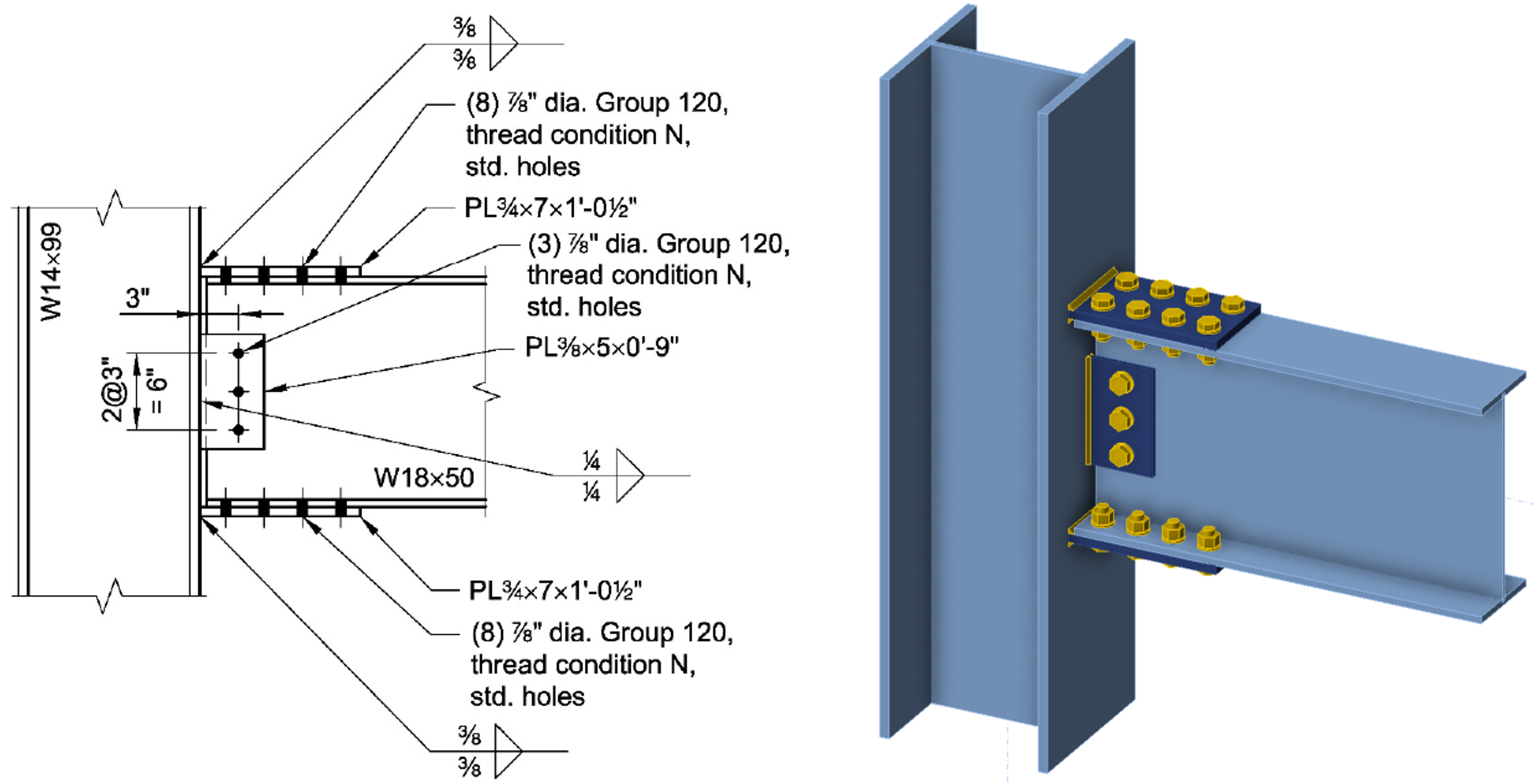
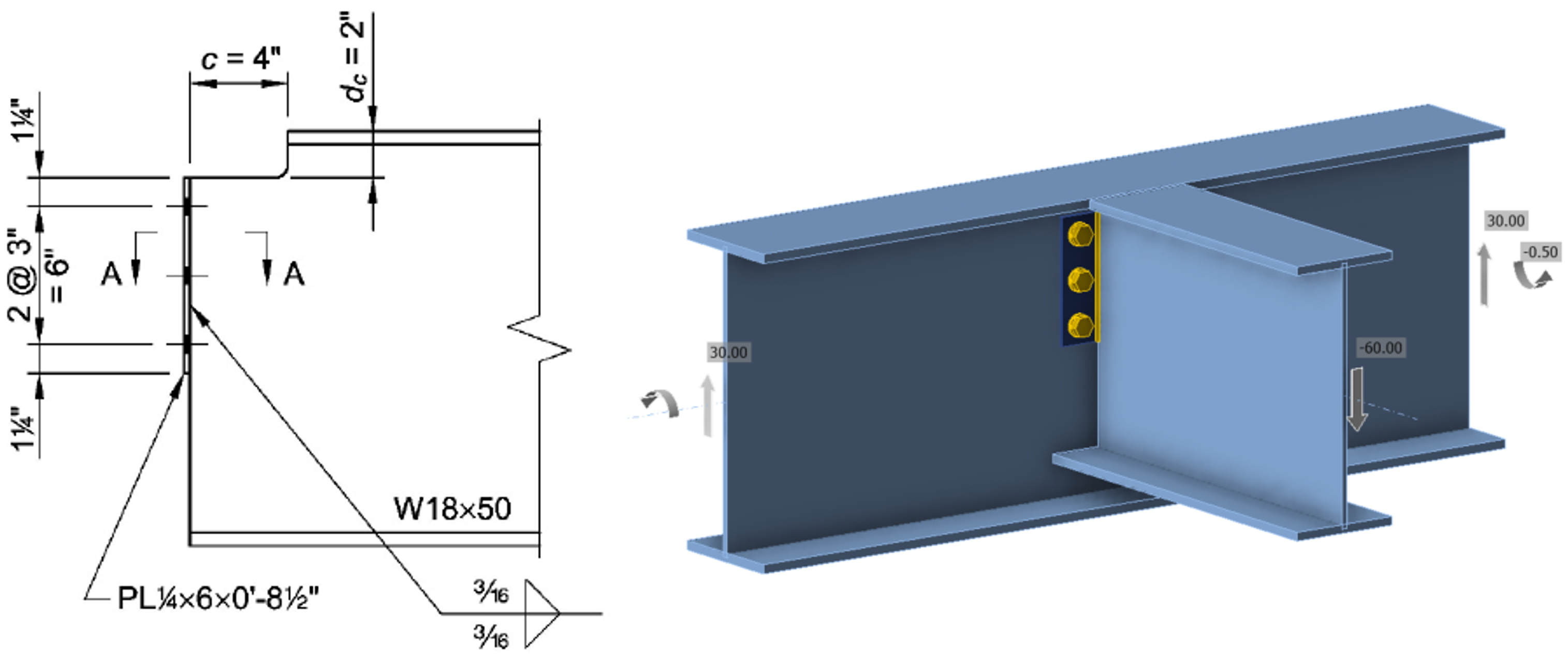
Connection 1 based on AISC Design Examples V16.0, Example II.B-1
Procedure
The procedure for this exercise assumes that the learner has a working knowledge of how to use IDEA StatiCa (e.g., how to navigate the software, define and edit operations, perform analyses, and look up results). Guidance for how to develop such knowledge is available on the IDEA StatiCa website (https://www.ideastatica.com/).
To perform the exercise, complete the following tasks:
1. Select one of the connections described below.
- Review the design example upon which the connection is based.
- Retrieve the IDEA StatiCa file for the connection provided with this exercise. Open the file in IDEA StatiCa.
2. List all the potential limit states that you can identify for the connection.
3. The connection in the provided IDEA StatiCa file has a modeling error. Run an analysis and view the results and identify the error. Visual results such as the deformed shape, plastic strains, or contact pressure are often the most helpful for identifying modeling errors.
- Describe the modeling error and how you identified it.
- What steps did you take that were helpful? What steps were not helpful?
4. Run several analyses with different magnitudes of applied load. For each level of loading, record the overall analysis output such as maximum plastic strain, maximum bolt utilization, and maximum weld utilization.
- Create plots of load vs plastic strain, load vs bolt utilization, and load vs weld utilization.
- Describe the behavior of the connection.
- What limit state controls the design of this connection? It may be necessary to view tabular results to identify the controlling limit state. Is this one of the limit states you identified previously?
- Are the plots of load vs utilization linear or nonlinear? What implications does this have for design?
5. Identify a parameter (e.g., geometric dimension, material property, analysis setting) that has a large influence on strength.
- Confirm that the parameter has a large influence on strength by changing the parameter and re-running analyses.
- Does the parameter have a large influence on strength?
6. Identify a parameter (e.g., geometric dimension, material property, analysis setting) that has a small influence on strength.
- Confirm that the parameter has a small influence on strength by changing the parameter and re-running analyses.
- Does the parameter have a small influence on strength?
Solution for Example 1
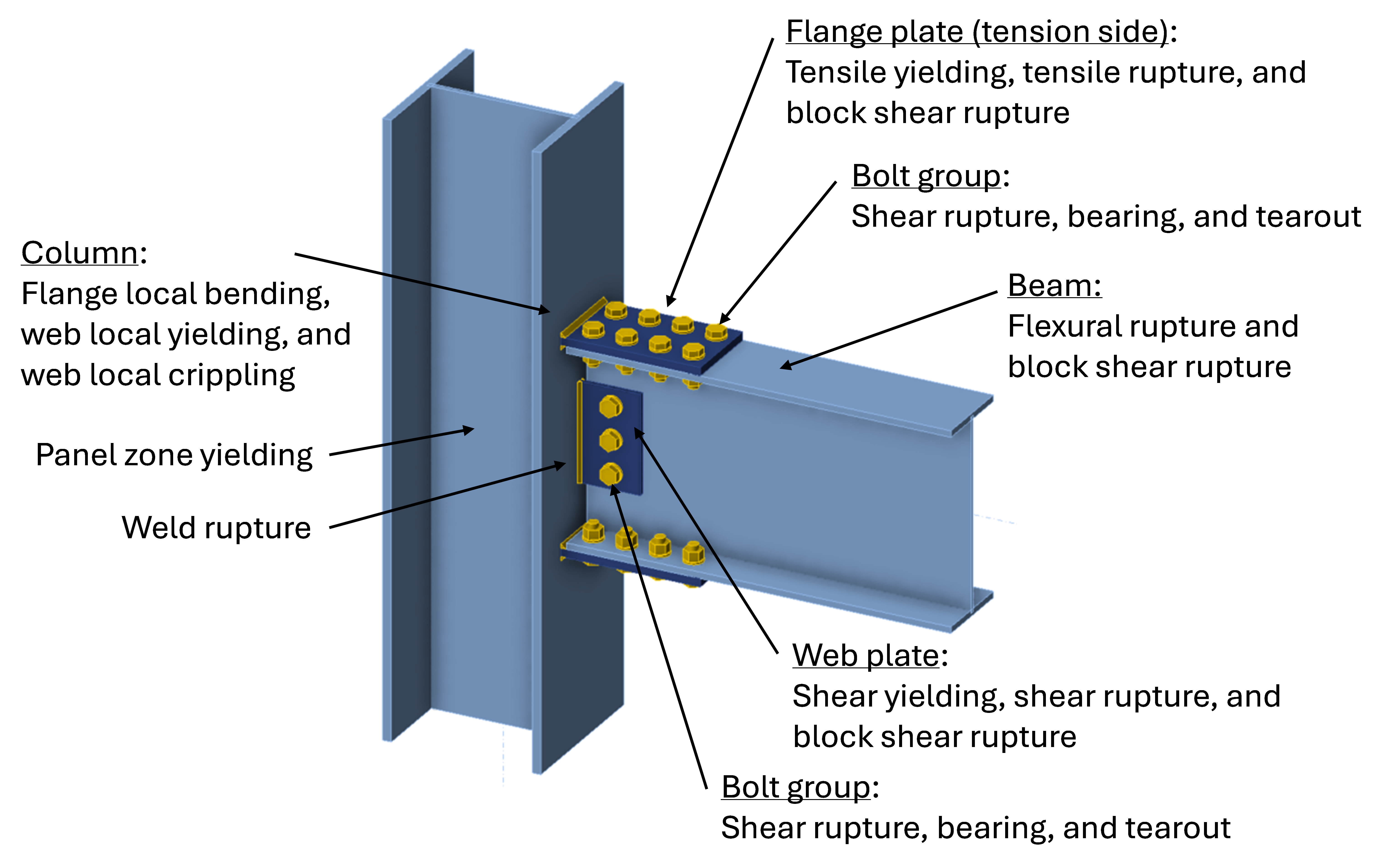
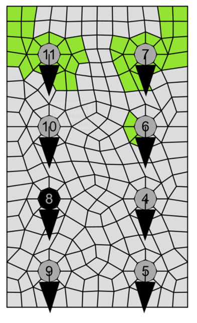
Limit states for the connection include those shown in the figure below:
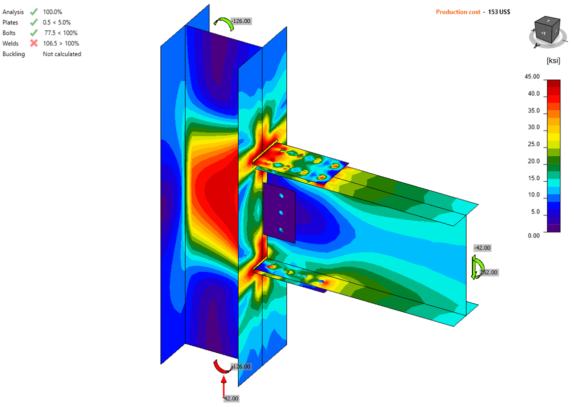
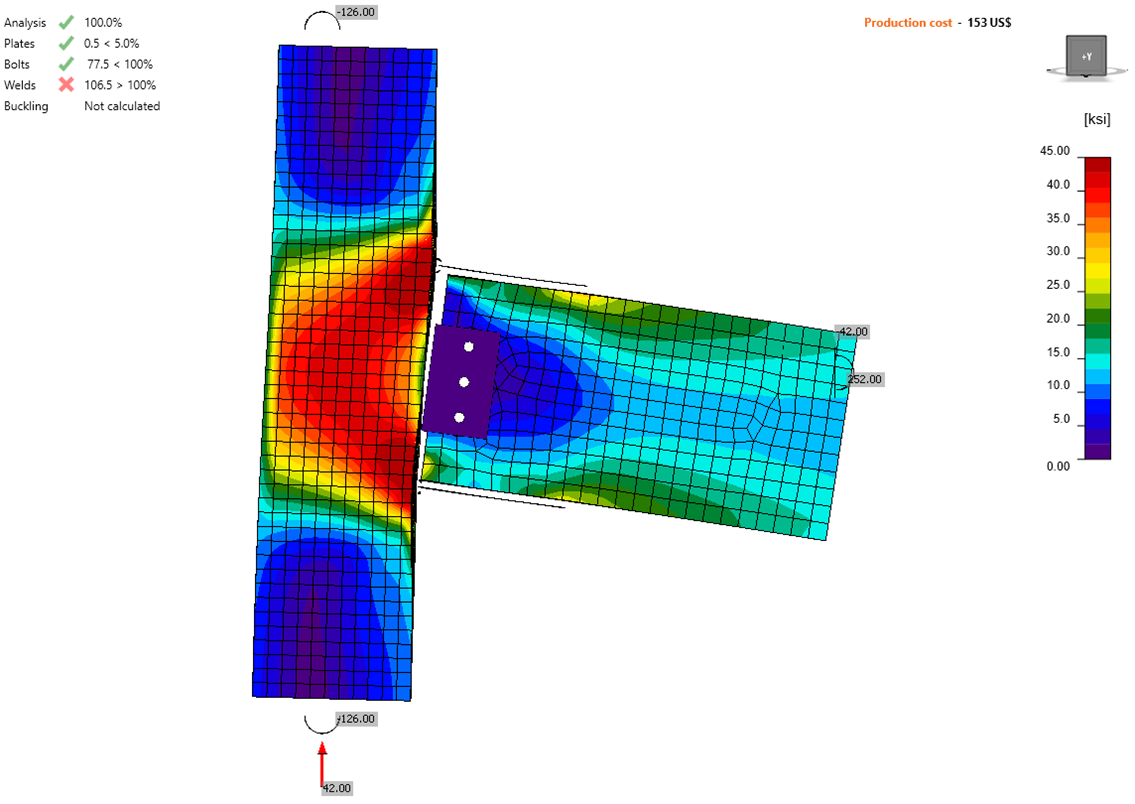
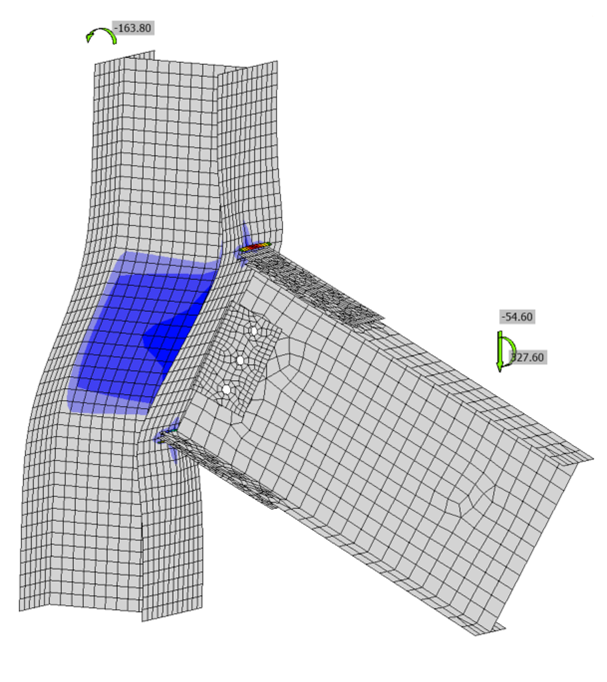
The provided model incorrectly omitted the weld between the web connection plate and the column flange. This is most clearly seen in the stress results (where the plate is shown to be unstressed) and in the deflected shape (where a gap opens between the plate and the column).
The missing weld could also have been identified by viewing the model, but the lack of weld is less visually apparent simply viewing the model. Viewing plastic strains is also less helpful for identifying the missing weld because many of the elements do not experience plastic strain.
Adding the weld corrects the error.
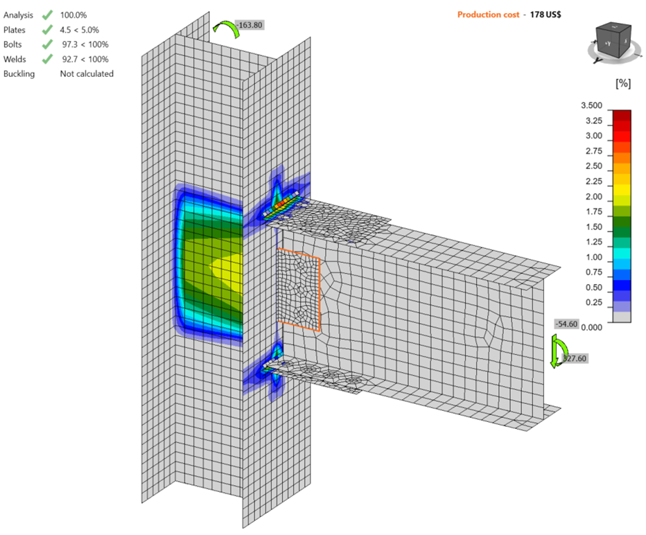
Analyses were performed at different levels of applied load ranging from 10% to 110% of the loads defined in the design example. Key output results from the analyses are shown in the table and figures below.
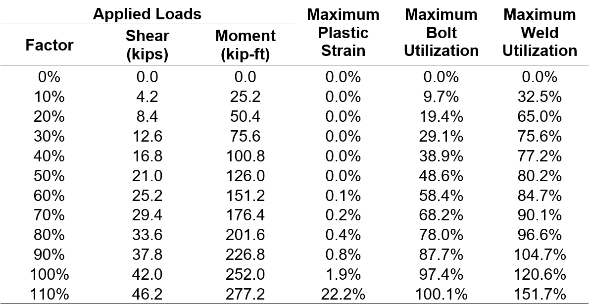
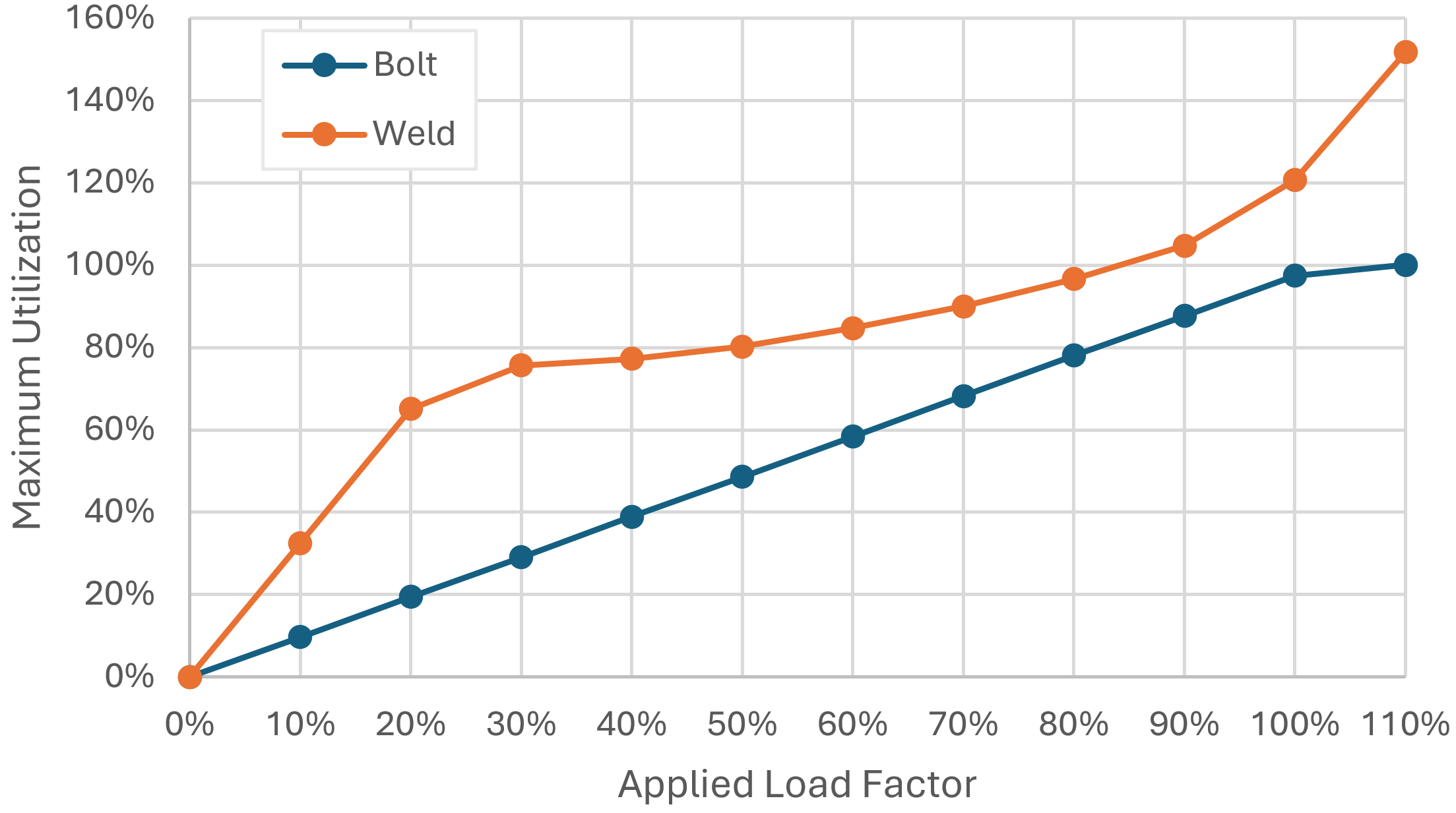
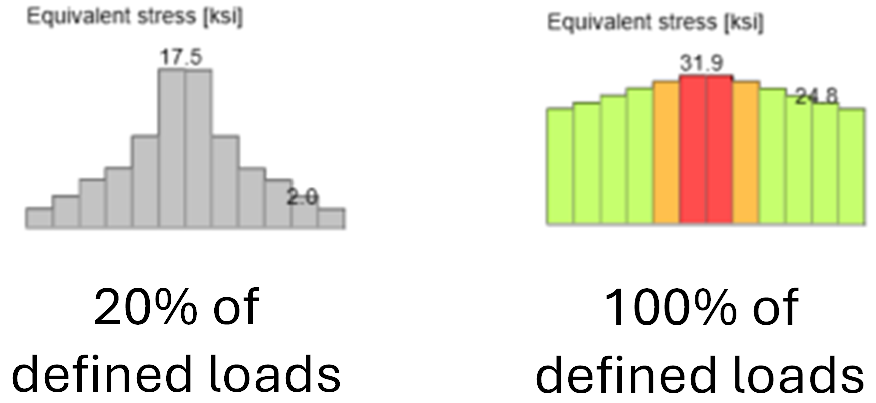
The utilization of the welds did not increase linearly with the applied loads. The weld utilization was 65% at 20% of the defined load, but the increase in weld utilization slowed with further increments in applied load. At low levels of loading, the stress in the weld was concentrated in the middle where there was a stiffer load path directly to the web of the column. At higher levels of loading, yielding of the weld material leads to more evenly distributed stresses and a slower rate of increase in the weld utilization.
The flange plate bolts experience primarily shear forces of nearly equal magnitude with the direction of force along the longitudinal axis of the beam. The bolts experience approximately 70% utilization at the maximum permitted applied loads. The relationship between applied load and bolt utilization is nearly linear.
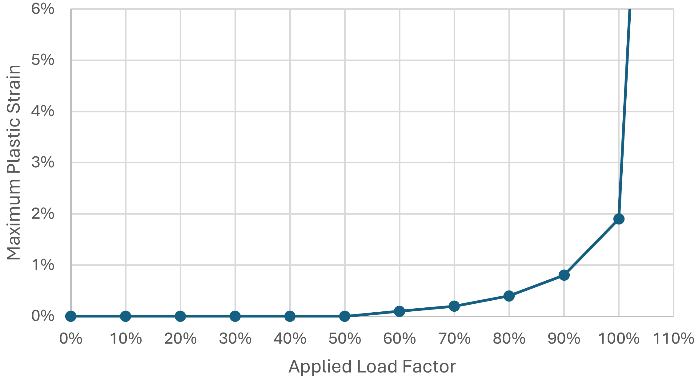
The plastic strain in the members and connecting elements at the maximum permitted applied loads is low. The maximum plastic strain of 0.4% occurs in the web of the column. Yielding in this location is associated with web local yielding or panel zone yielding, but the column has not reached these limit states at the defined loads. As seen in the plot above, the maximum plastic strain increases dramatically with increased loading. At 130% of the defined loads, panel zone yielding is clearly evident (however, the flange plate welds are far overutilized at this level of loading).
The analyses showed that the flange plate welds control the strength of the connection, so increasing the size of those welds should significantly increase the strength of the connection. Loads of up to 130% of the defined loads can be applied to the connection after increasing the size of the weld to 5/8 in. With the larger welds, panel zone yielding and bolt shear rupture control the strength of the connection.
Other parameter changes expected to have a significant influence on the strength of the connection are increasing weld filler metal strength and increasing the width of the flange plate.
List of other connections
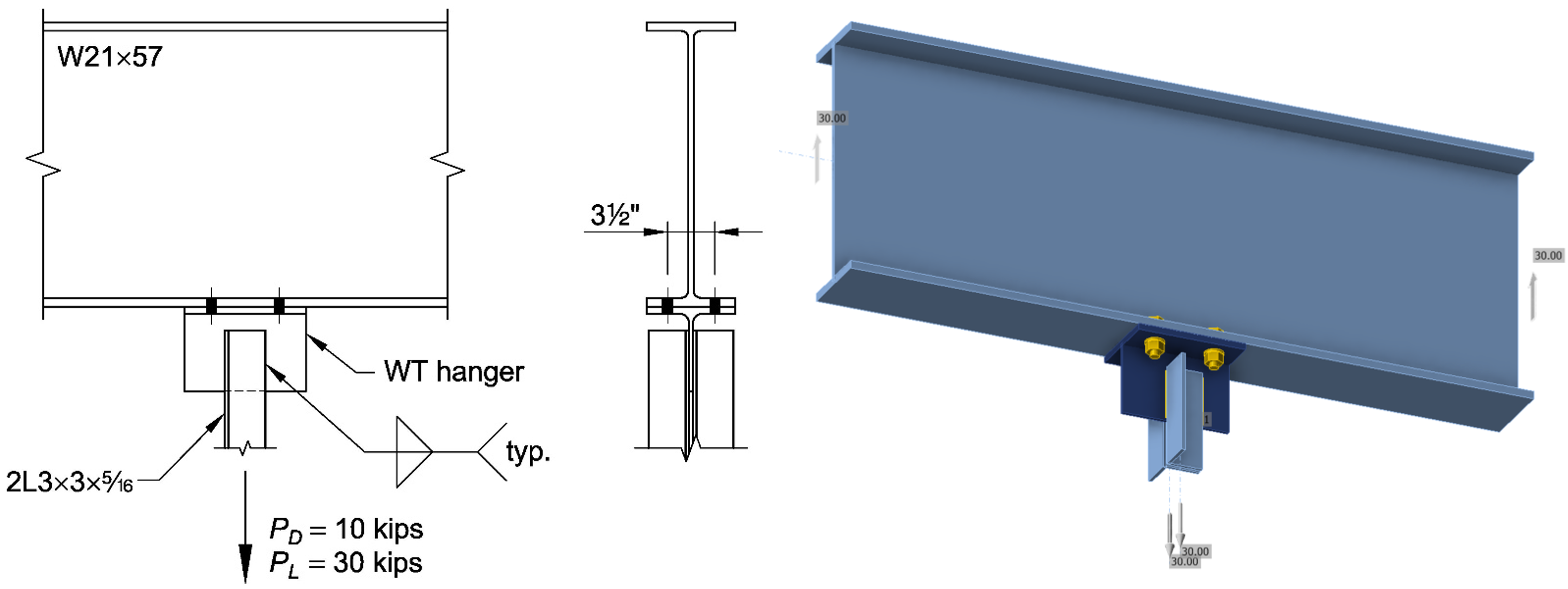
Connection 2 based on AISC Design Examples V16.0, Example II.A-11A
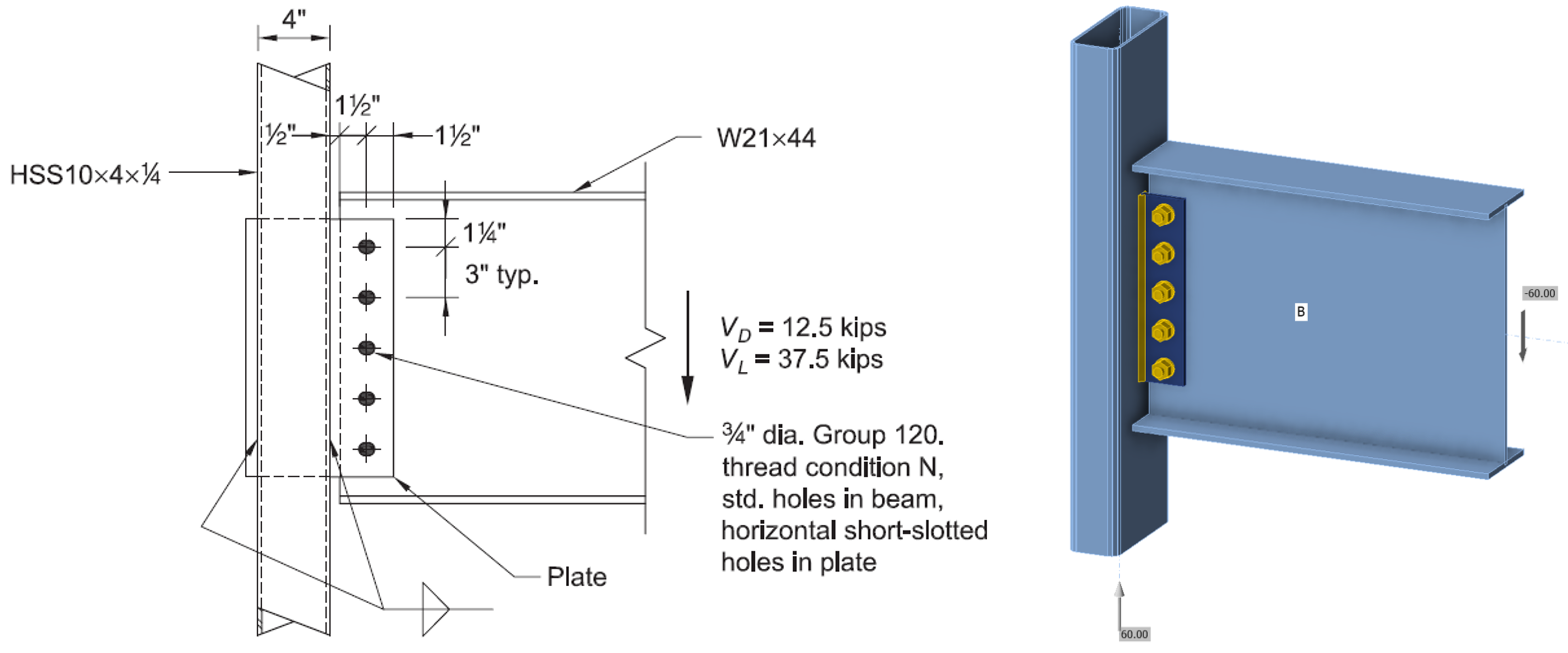
Connection 3 based on AISC Design Examples V16.0, Example II.D-1
Connection 4 based on AISC Design Guide 24 Example 5.3
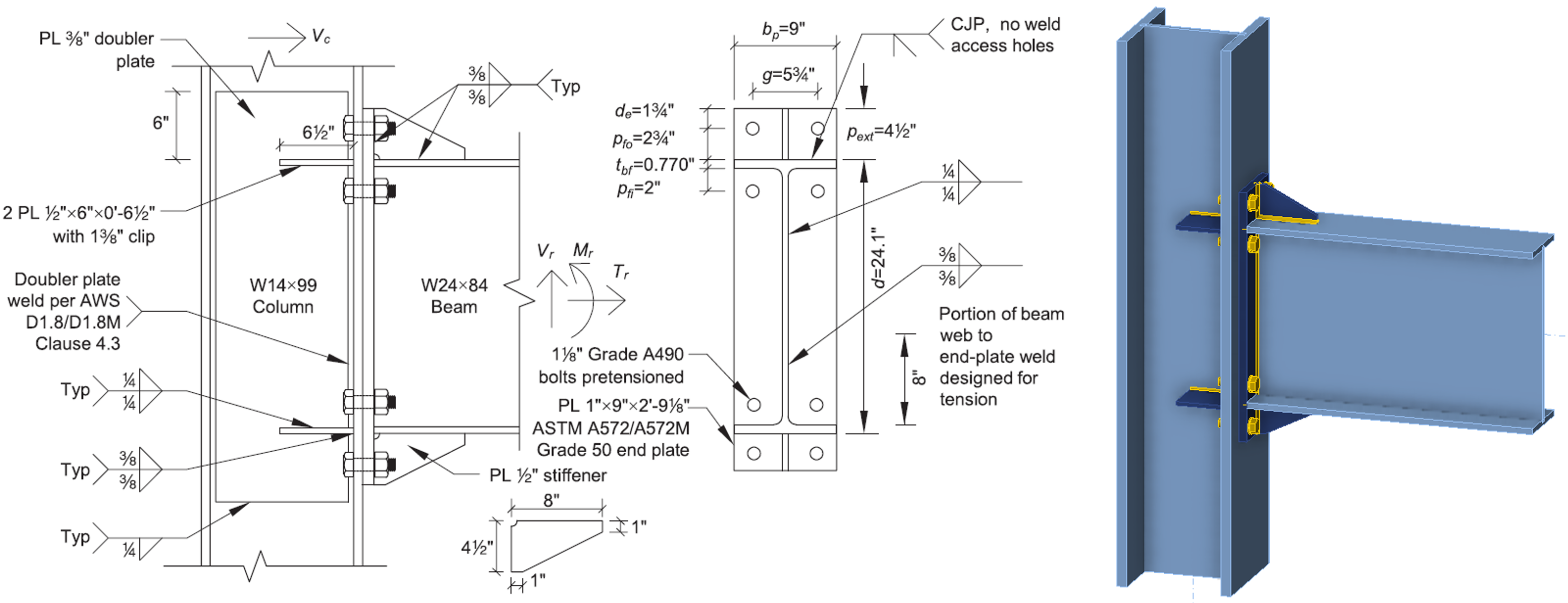
Connection 5 based on AISC Design Guide 39 Example 5.3-2 with the column size modified to W14x176 to eliminate the need for a doubler plate.
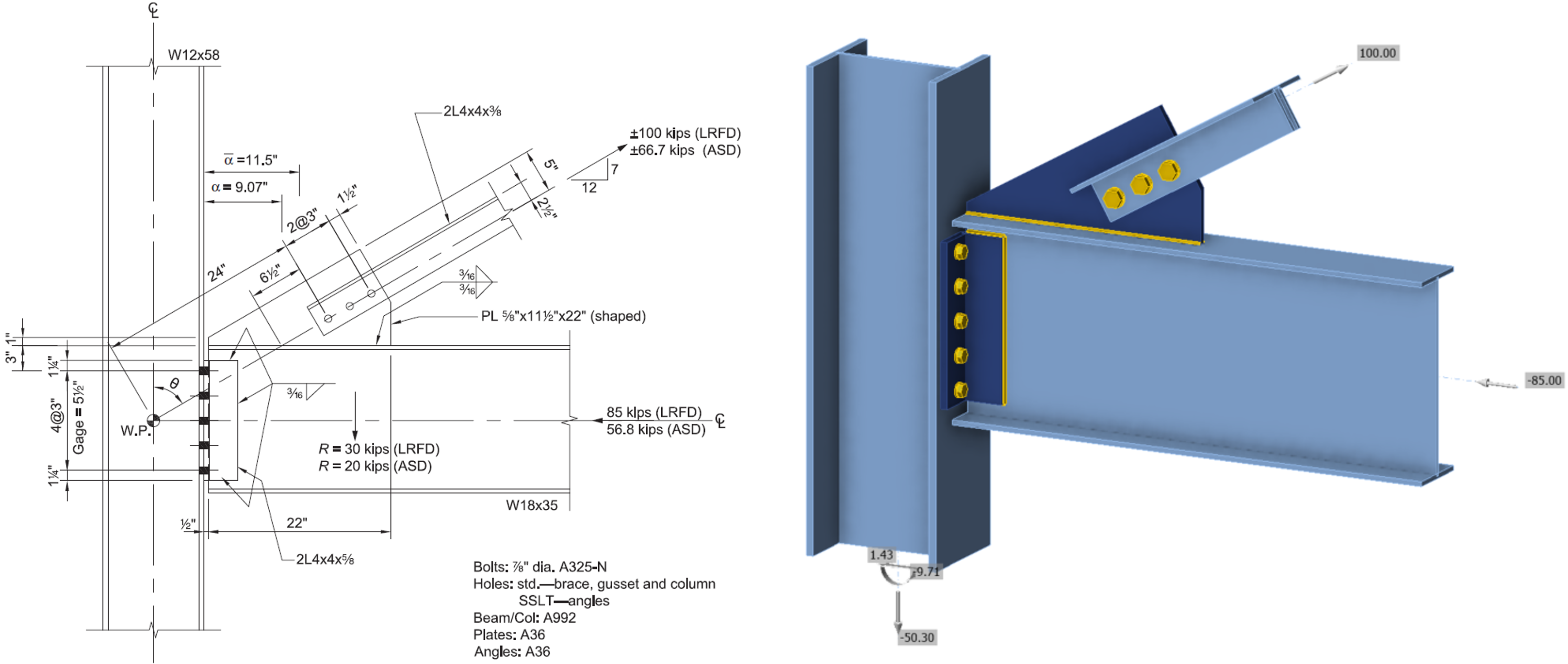
Connection 6 based on AISC Design Guide 29 Example 5.4
References
AISC. (2022). Specification for Structural Steel Buildings. American Institute of Steel Construction, Chicago, Illinois.
AISC. (2023). Companion to the AISC Steel Construction Manual, Volume 1: Design Examples, v16.0. American Institute of Steel Construction, Chicago, Illinois.
Eatherton, M. R., and Murray, T. M. (2023). End-Plate Moment Connections. Design Guide 39, American Institute of Steel Construction, Chicago, Illinois.
Muir, L. S., and Thornton, W. A. (2014). Vertical Bracing Connections – Analysis and Design. Design Guide 29, American Institute of Steel Construction, Chicago, Illinois.
Packer, J. A., and Olson, K. (2024). Hollow Structural Section Connections. Design Guide 24, Second Edition, American Institute of Steel Construction, Chicago, Illinois.
Tamboli, A. (Ed.). (2017). Handbook of Structural Steel Connection Design and Details, Third Edition. McGraw Hill, New York, NY.