Bolted connections
Introduction
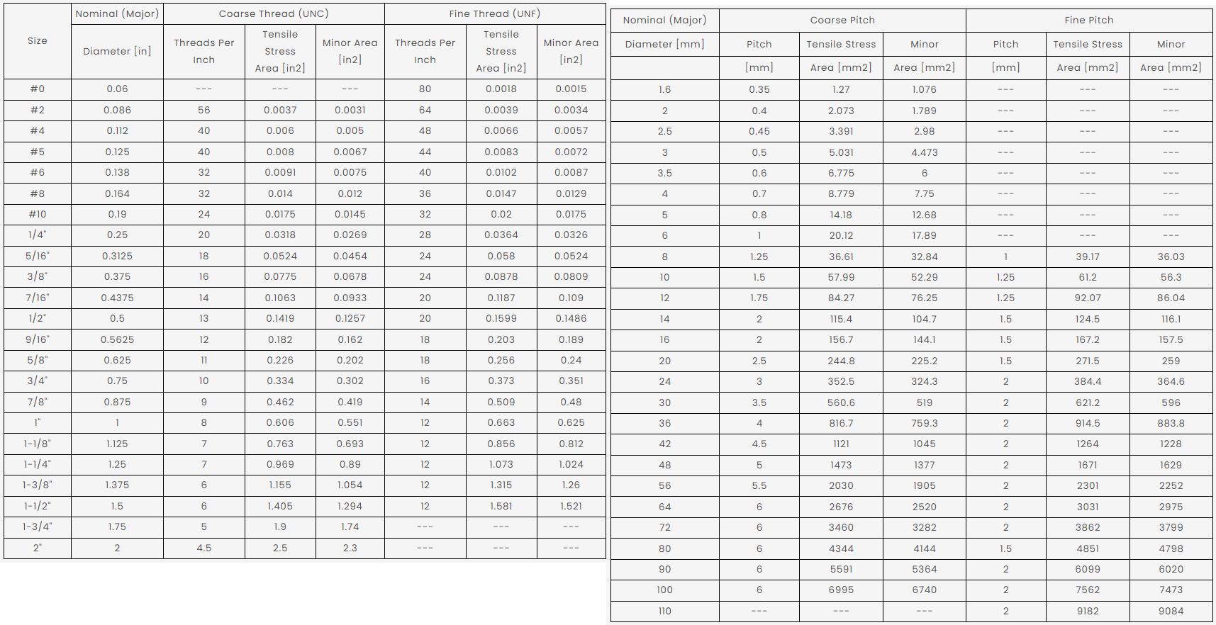
In essence, bolted connections transfer forces from one or more members into other members and on into the foundations. They do this by bearing, tension, and occasionally friction. They are suitable for almost any type of joint. More often than not, however, the resultant stiffness of the joint is not re-considered in the overall design, which sometimes should not be overlooked. Bolts come in a variety of different sizes (see below) and grades (bolt material), depending on the standard and region. In some countries (not a million miles away), they have access to both metric and imperial sizes – which can be a double-edged sword at times! As I have also discovered, there are apps for smart phones and YouTube videos that help specifiers and engineers...
Going back to my structures classes, one of the first connections we undertook was a 'simple' bolted connection taken from an example steel portal frame. To show how long ago this was, we used a pencil and graph paper! The calculations that ensued could not have been more than one side of A4 paper.
How things have changed!
In those early days, I could never have imagined the changes in methods and reasoning – but that is another topic, for another day and another article.
Bolted Joint Connections
The burning question is: can a bolted connection ever be considered 'simple' even though they are often described as such? Connections are complicated (whether we like it or not) and it takes an engineer to understand and design them. There are 'simple' forms for sure and yes - connections can still be designed and checked using traditional methods, most definitely and this is where every connection engineer should begin their journey, but is there a better way?
There are several ways to undertake designs but many options oversimplify the process by allowing a narrow window of applicability or ignoring key effects - one of the biggest problems still is the reliance on envelope forces and non-coincident load effects. Is this an over-simplification we should really be avoiding? Probably! Many firms have adopted a series of spreadsheets, but this also raises concerns about verification and keeping them current.
I also remember writing end reactions on a drawing based on shear alone and one load combination – always for the steel fabricator to design the connection :-). Those days are definitely gone. But far too many engineers are trying to stay with the old ways and mix the old approach with modern codes and methods – which results in poor, inefficient, over-designed connections.
Pros and cons of bolted connections
Bolted joint connections are great as they are relatively easy to install, maintain, and inspect. They might not be as cheap to fabricate as you think as they can generate more material, have bolt holes (which cost more) and larger stress concentrations. They can also lead to site issues (speaking from experience, here), where the wrong bolts (or no bolts) are sent with the beam. In some situations, they can offer the designer some comfort as, invariably, there is some additional capacity in a bolted connection (if done correctly). However, no connection is infallible! Many failures have been attributed to poor bolt details – inserted upside down/incorrect bolt assembly for the intended use. It is, therefore, very important to take into consideration the detailing rules and any special measures should be noted on the production/erection drawings/information.
Trying to simplify the process by choosing a 'simple' connection can often result in a more expensive joint to fabricate. It is quite possibly time to consider material cost and CO2 more than design costs...
Conversely, as bolted connections become more complicated – either down to geometry or applied loading, or both – they become even harder to design and code-check. A simple approach, possibly by breaking down a complicated connection into simpler parts, will not work.
Design pitfalls
There are many possible issues that can arise when designing a connection but by far the most widely seen on our helpdesk are the 'surprising' tension forces in the bolts when no such force is being applied to the bolt.
Where are these tensile forces and tensile stress coming from? I would refer you to look into prying forces arising from flexible plates in your joint design. These can sometimes be more onerous than the shear force components! As a side note, if you want to see how these can affect your design, try increasing your steel material by several orders of magnitude, and (if you do this in steps), you can see that as the flexibility decreases, the bolt forces tend towards the 'expected' outcome.
Another aspect of bolted connections that can occur is when slip-critical connections or preloaded bolts are required. Not only does this affect the design approach but also the site works. The testing and certification of such bolts on site is problematic and expensive. As a young engineer, I was told to avoid these if at all possible – I wonder why?
A bolt usually goes through a bolt hole. These are termed clearance holes. As bolt diameters increase so does the diameter of the clearance hole (or they should). Additionally if a material finish or surface preparation is applied then the clearances should be increased - galvanisation is a good example here.
I mentioned at the start of this article the approach I started with an end reaction from a simple load combination, usually factored and then rounded up. This might even have been tabulated based on the size of a member and its capacity. This approach is still in use today in many countries, and can lead to issues in connection design. The problem is one of balance: balancing the engineering with the resultant details. Structural design has evolved and so has the software used. Indeed, one could argue that a structure cannot be designed (efficiently) without software. How best to use all of this software to model and design your bolted connections?
The CBFEM approach
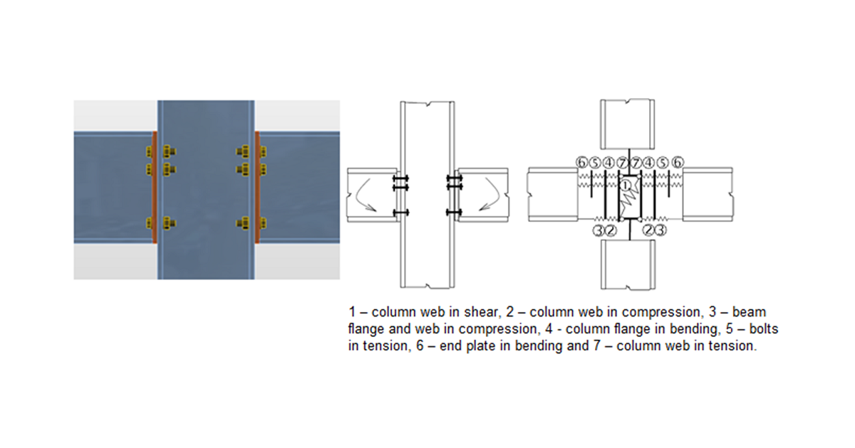
How do we at IDEA StatiCa leverage the technology behind CBFEM? This methodology is built into IDEA StatiCa Connection. Bolts are treated as dependant non-linear springs. This allows any connection geometry, with any applied loading, to be modelled, calculated, and code-checked. Additionally, the stability and other effects can be checked – after all, it is unlikely that the 'simple' approach will be good enough!
One of the arguments often cited is that this is a 'sledgehammer to crack a walnut' approach. However, in recent releases, we are making it even easier to model and design simple connections by using AI, Visual Programming, and API enhancements, using the power of our computers to drive down the monetary and CO2 cost of easy connections.
Added to this is the ability to extract the load effects/connections from several major FEA/BIM solutions from providers such as Autodesk, Trimble, CSi, Nemetshek, etc., which really impacts the efficiency and accuracy as the load effects or the connection itself are passed to IDEA Connection via Checkbot – a sort of hub for seamless information exchange between differing solutions.
IDEA StatiCa Connection is the best of both worlds! It will give you accurate, verifiable results that can be code-checked.
One thing is for sure, I will never treat a bolted connection as simple ever again!
Maak vandaag nog een proefrit met de nieuwste IDEA StatiCa
Further reading