Verification of longitudinal bracing
Motivation
As already stated, longitudinal bracing plays a crucial role in steel hall structures. This reliable element is widely used in construction due to its effectiveness in enhancing the overall bracing's behavior. Advanced simulation tools, such as IDEA StatiCa Member, enable engineers to accurately calculate buckling length and consider the impact of eccentric connections, further optimizing the design and performance of longitudinal bracing systems.
Project
The project was carried out by HESCON s.r.o. with engineer Lucián Lesňák being responsible for designing and checking the code of the hall. The hall has a width of 8.3 meters, a length of 22.6 meters, and a height of 2.3 meters. The key element that requires analysis is a 50x50x3 mm SHS profile that is welded to an IPE 180 on an eccentric gusset plate.
Analytical solution
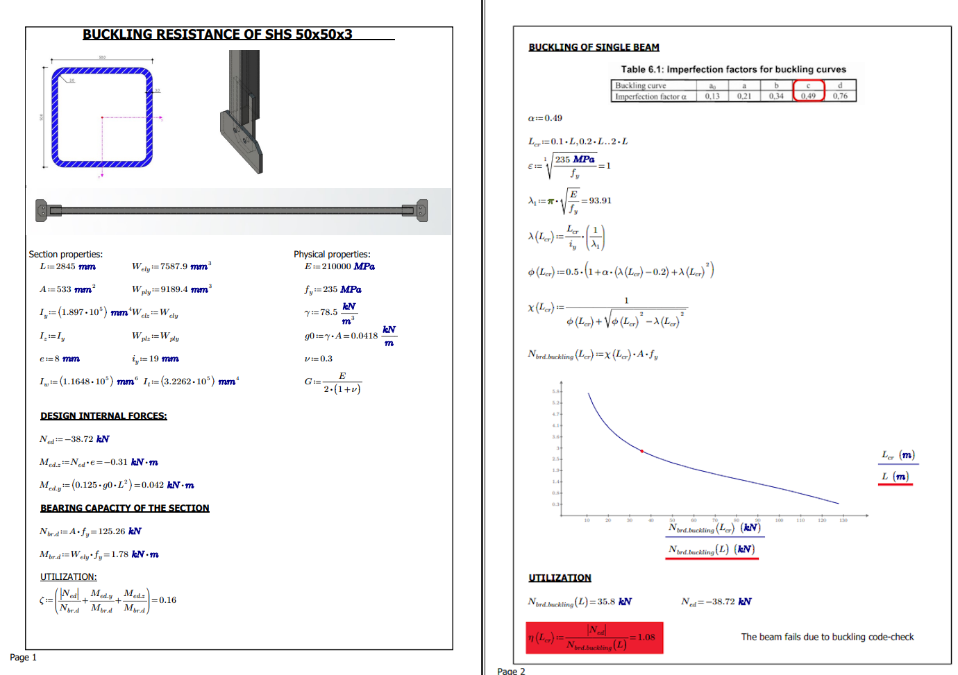
To perform advanced analysis, it's crucial to hand-calculate and comprehend the critical member's behavior. The hand calculation is performed by using EN-1993-1-1. The calculation considers the design axial force and code–checks for critical axial buckling resistance.
The benefits of hand calculations:
Understanding of principles: Performing hand calculations allows engineers to gain a deep understanding of the fundamental principles and theories behind structural analysis and design. It helps them develop a strong foundation of knowledge and problem-solving skills.
Verification and validation: Hand calculations serve as a valuable tool for verifying and validating the results obtained from computer-based analysis and design software. By performing independent calculations, engineers can ensure the accuracy and reliability of their designs.
Sensitivity analysis: Hand calculations enable engineers to perform sensitivity analysis by manually adjusting various design parameters and observing their impact on the overall structural behavior. This helps in optimizing the design and identifying critical factors affecting structural performance.
Quick estimations: Hand calculations provide a quick and efficient way to estimate structural responses and check the feasibility of preliminary design concepts. They can be performed during the early stages of a project when detailed computer-based analysis may not be necessary.
Enhanced problem-solving skills: By relying on hand calculations, engineers develop strong problem-solving skills and critical thinking abilities. They learn to break down complex structural problems into simpler components, analyze them systematically, and arrive at accurate solutions.
Educational purposes: Hand calculations are often used as teaching tools in structural engineering education. They help students grasp the underlying concepts, theories, and equations involved in structural analysis and design, fostering a deeper understanding of the subject matter.
Overall, hand calculations play a crucial role in the field of structural engineering by promoting a thorough understanding of principles, ensuring accuracy, facilitating optimization, enabling quick estimations, enhancing problem-solving skills, and serving educational purposes.
The imperfections of hand calculations:
Human error: The accuracy of hand calculations is highly dependent on the engineers' skills, experience, and attention to detail. Errors in data entry, unit conversions, or mathematical calculations can lead to incorrect results, compromising the safety and reliability of the structure.
Limited complexity: Hand calculations are typically limited to simple and straightforward structural systems. As the complexity of the structure increases, so does the complexity of the calculations, making it more challenging to perform them accurately and reliably.
Time-consuming: Hand calculations can be time-consuming and labor-intensive, particularly for large and complex structures. This can lead to delays in project timelines and increased project costs.
Limited optimization: Hand calculations are unsuited for optimization and iterative design processes. They are typically performed after the preliminary design has been established, limiting the ability to explore and optimize different design options.
Limited visualization: Hand calculations provide limited visualization of the structural behavior, making it challenging to identify potential failure modes or visualize the overall structural response.
While hand calculations offer several benefits, they are not without limitations and imperfections. It is essential to balance the advantages and disadvantages of hand calculations with other analysis tools and techniques to ensure accurate and reliable structural designs.
Numerical simulation
The structural engineers thoroughly verified the IDEA Statica model by comparing it against an ABAQUS solution. This process was aimed at ensuring that the model was robust and dependable, providing a reliable foundation for the structural design. By conducting such a detailed analysis, the engineers were able to identify any potential areas for improvement, allowing them to fine-tune the model and make it even more accurate. Ultimately, this verification process helped to increase the overall quality and safety of the structural design.
Assumptions of IDEA StatiCa and ABAQUS
The assumptions utilized to simulate the numerical twin have been incorporated into ABAQUS. For modeling purposes, the S4R element was selected. This element is a standard linear quad element that employs reduced integration, hourglass control, and finite membrane strains. To model the bolts, a join + revolute MPC has been used, along with kinematic coupling to distribute the stresses in the nut and bolt head area. Due to the presence of butt welds throughout the model, linear constraint ties have been used to bind the plates together. The material diagram employed in the simulation is identical to that used in the IDEA StatiCa model. The contacts have been set as frictionless. The simulation has undergone a general static analysis with a large displacement analysis to evaluate its performance. The mesh in the area of the connection reaches a maximum 2 mm size and the SHS 50/50/3 is divided into 5 mm mesh sizes.
- Shell finite elements
- Bolts – nonlinear springs (interaction tension and shear)
- Welds – special elements bonded the plates via MPC
- Frictionless contacts – penalty method
- Material – bilinear diagram with hardening (isotropic rule for hardening)
- Linear buckling analysis – material nonlinear analysis used as the preload; contacts are free during the analysis
You can read the theoretical background here.
Analytical model
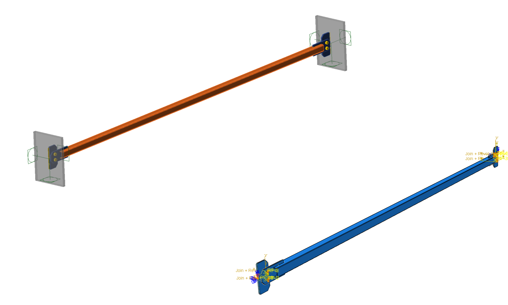
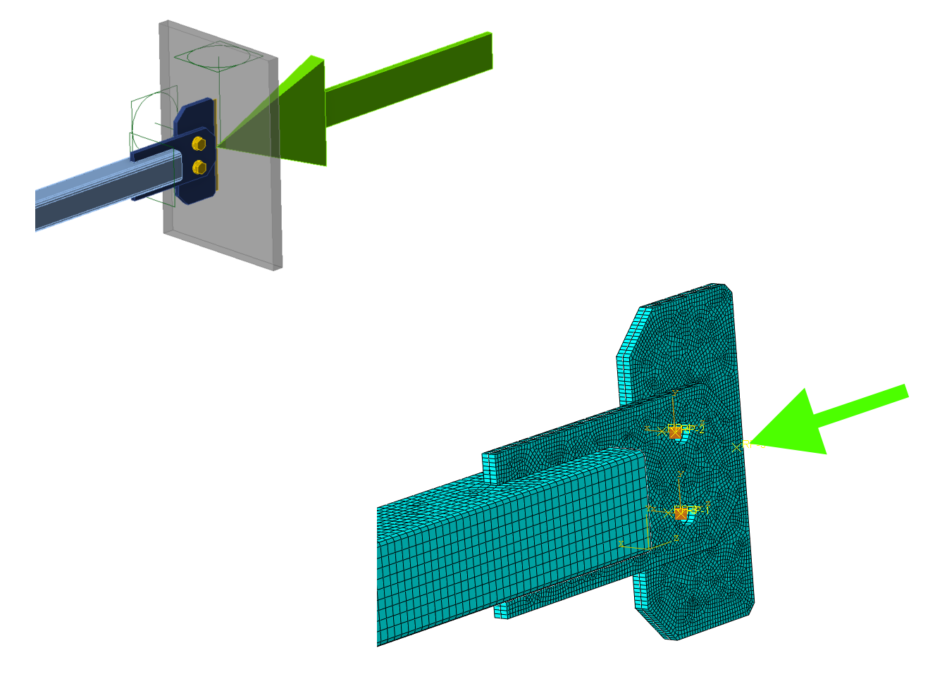
The analytical model has been constrained in all six degrees of freedom through one connection. The second connection restrains all rotations and translations except for the translations along the axis of the SHS member. This is due to the concentrated axial forces that are transferred to the model itself.
01) IDEA StatiCa model(left), ABAQUS model(right)
Mesh
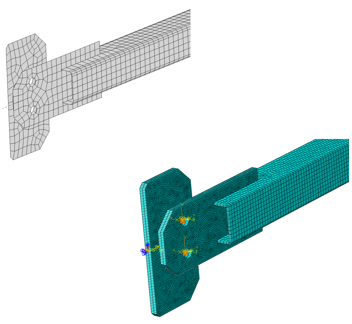
The default mesh size was utilized for the IDEA StatiCa solution, whereas ABAQUS employed a mesh size within a 2-5 mm range.
02) IDEA StatiCa mesh(left), ABAQUS mesh(right)
Load
A concentrated compressive force initially distributed over the rigid support condition was utilized in IDEA StatiCa, while in ABAQUS, a distributed coupling equation with uniform weighting was employed to propagate the concentrated force to all edges of the plate. The concentrated force was subsequently used to model the plate itself.
03) IDEA StatiCa load(left), ABAQUS load(right)
Geometrical and material nonlinear analysis
Geometrical and material nonlinear analysis is a numerical method used to simulate the behavior of structures under large deformations and nonlinear material responses. This type of analysis takes into account the nonlinearities arising from both the geometry and material properties of a structure. It is commonly used to analyze structures that undergo significant deformation, such as in the case of plastic deformation or large deflections. The results of this analysis can help engineers optimize the design of structures and predict their behavior under different loading conditions.
The primary aim of the analysis is to evaluate the stresses and displacements. The Newton-Rhapson method has been employed in each increment to obtain equilibrium on the deformed structure. All non-linearities, including the material and contacts, have been considered.
Equivalent stress
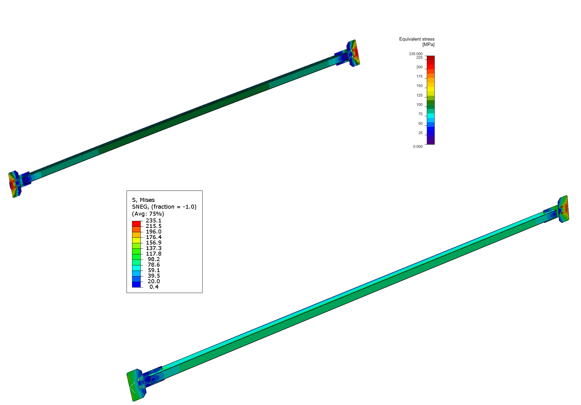
The equivalent stress has reached the same redistribution in both models.
04) IDEA StatiCa equivalent stress(left), ABAQUS equivalent stress(right)
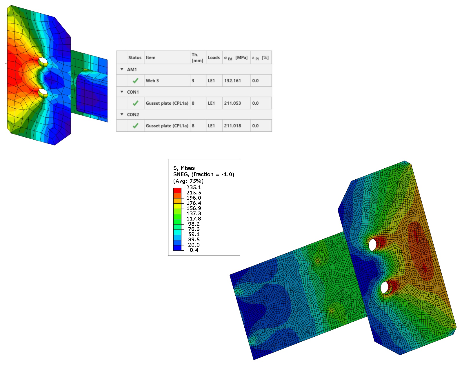
The detailed results have provided a more profound understanding of the outcomes. The equivalent stress (ES) reached its highest value of 211 MPa in IDEA StatiCa at the integration point, whereas in ABAQUS, it was 235 MPa. This increase in ES in ABAQUS can be attributed to the finer mesh used, which resulted in integration points being closer to the concentrated stress area near the opening.
05) IDEA StatiCa equivalent stress(left), ABAQUS equivalent stress(right)
Opening in the contact
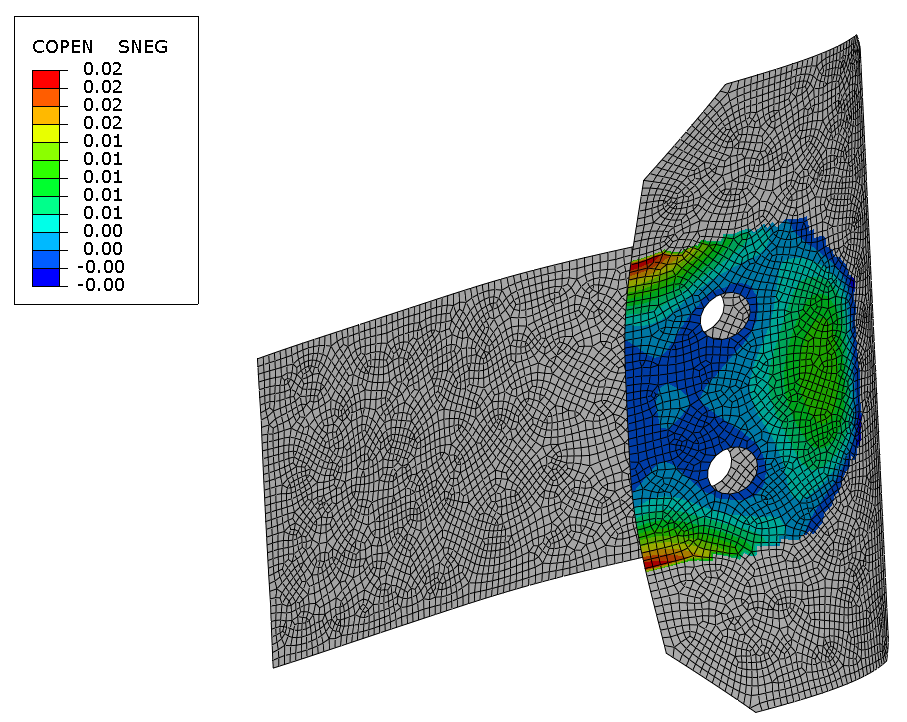
ABAQUS provides an additional output called "COPEN", which provides information about the gap or opening between two plates.
06) ABAQUS opening in contact
Deflections
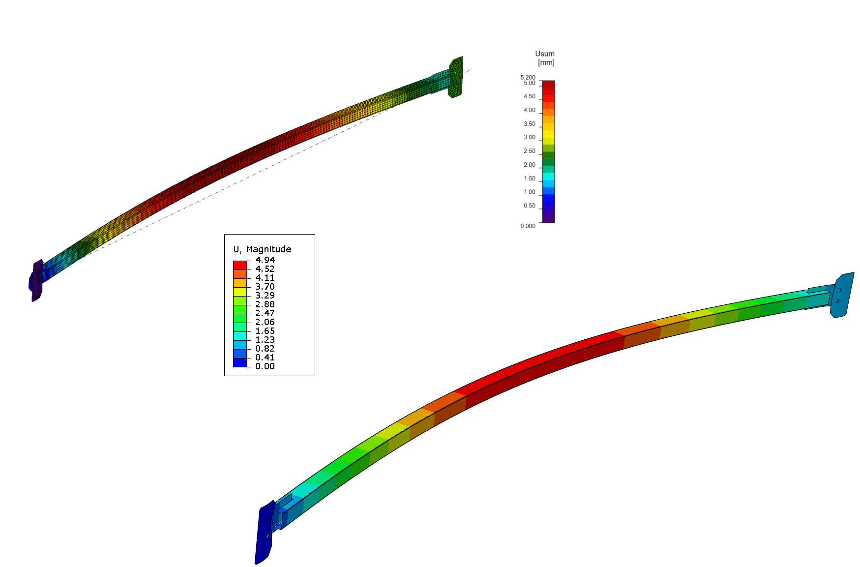
The material response is elastic as the stresses only affect the local area near the opening's yield point. The deflections indicate an excellent match in the results.
07) IDEA StatiCa total deformation(left), ABAQUS total deformation(right)
Linear buckling analysis
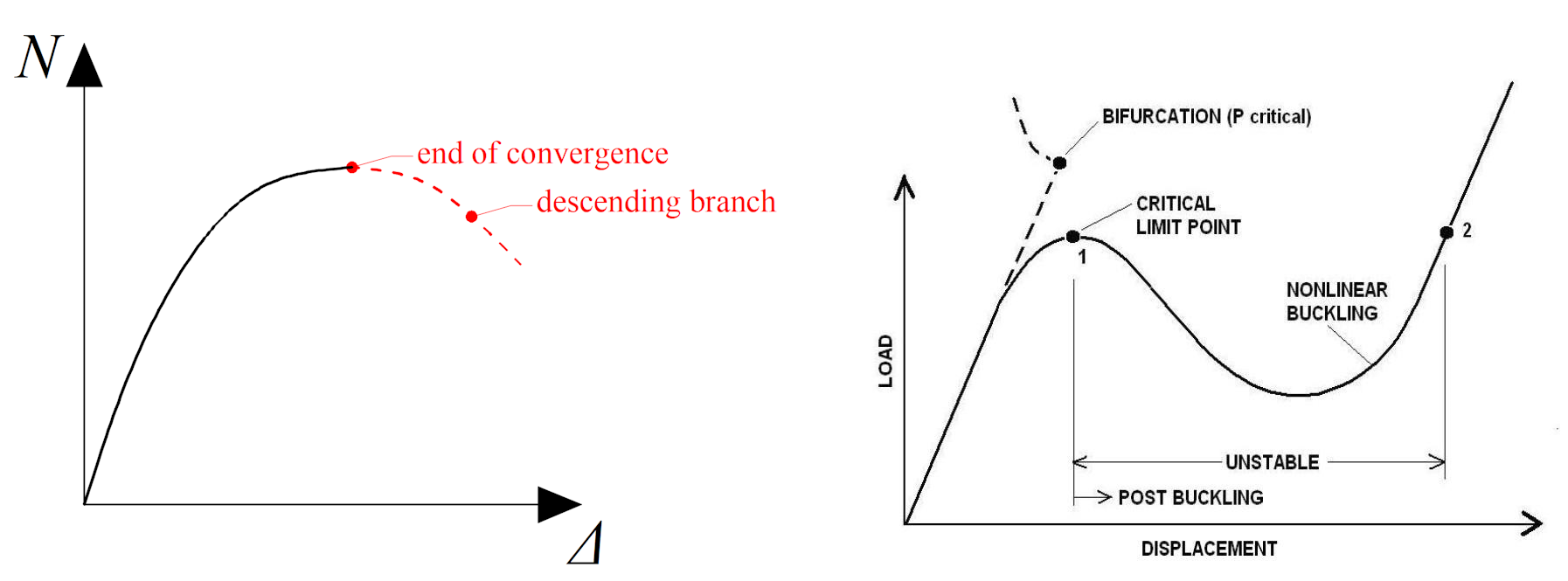
Linear buckling analysis is a numerical method used to predict the stability and buckling behavior of structures under applied loads. It involves determining the critical load or load factor at which a structure becomes unstable and experiences buckling. This analysis helps engineers assess the structural integrity and design of various components, such as columns, beams, and shells.
08) Linear vs. nonlinear buckling
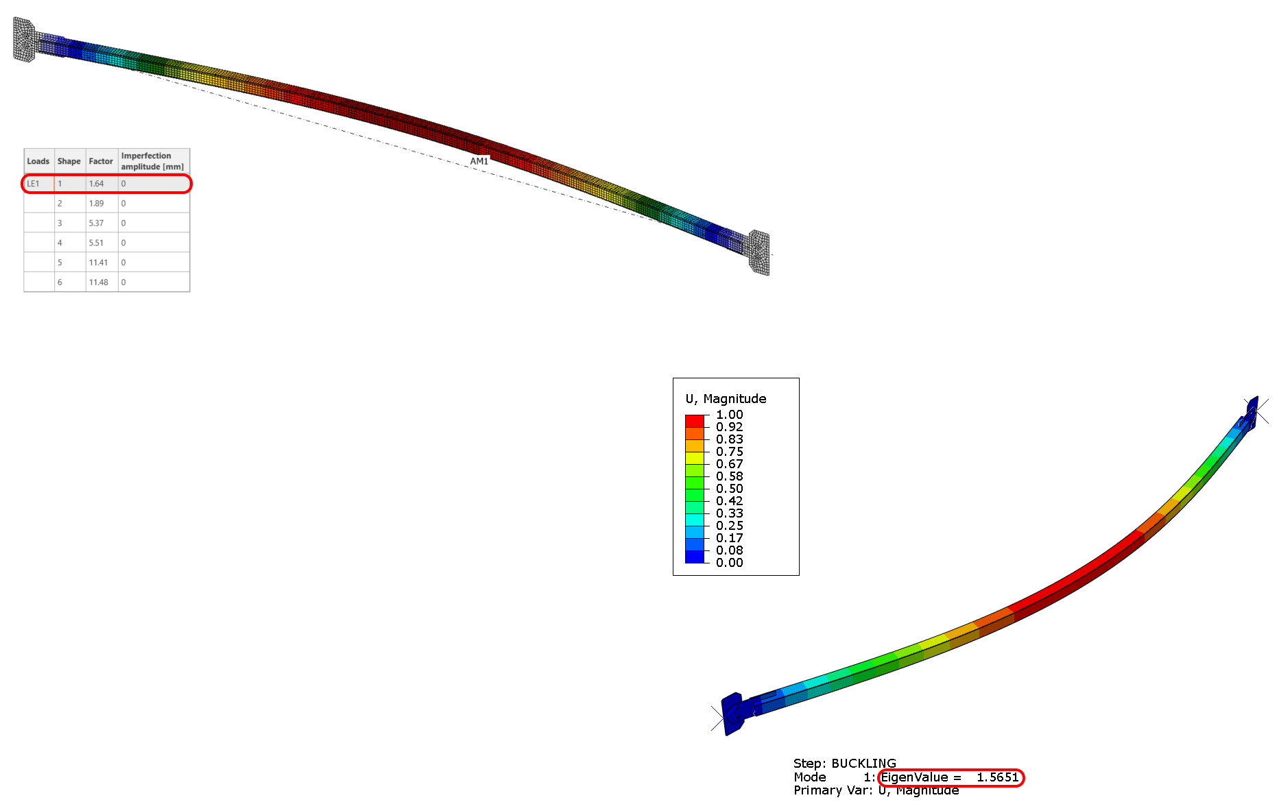
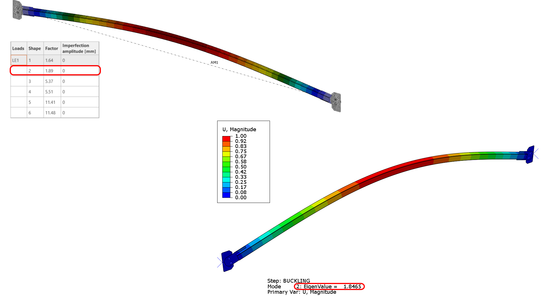
One of the most significant contributions of linear buckling analysis is the generation of eigenmodes and critical load factors, which help structural engineers to anticipate and prevent any potential structural failures. Based on the verification, a match can be seen between IDEA Statica and ABAQUS with very little error. The domain first buckling mode has reached a critical factor of 1.64 vs. 1.57 in ABAQUS.
09) IDEA StatiCa first buckling shape(left), ABAQUS first buckling shape(right)
10) IDEA StatiCa second buckling shape(left), ABAQUS second buckling shape(right)
Imperfection
In accordance with EN 1993-1-1, the inclusion of imperfections is crucial to the integrity of any analysis. The local imperfections are contingent upon the buckling curve, as outlined in Table 6.1, and the classification of the section. In light of the SHS 50/50/3's classification under buckling curve C, the corresponding local imperfection is 14 mm.
11) Imperfection values
Geometrical and material nonlinear analysis with imperfection
Geometrical and material nonlinear analysis (GMNIA) is a type of analysis used in engineering to study the behavior of structures under extreme loads. This analysis takes into account both the geometric nonlinearity (changes in shape) and material nonlinearity (changes in material properties) of a structure, as well as any initial imperfections or deformations present in the structure. By considering these factors, engineers can understand better how a structure will behave under loading and make informed decisions about its design and safety.
The analysis seeks equilibrium in every increment using the initial deformed shape from Linear Bifurcation Analysis's (LBA) imperfection. If equilibrium cannot be found, the solution stops.
- Material nonlinearity – occurs when the material can no longer deform elastically and begins to yield plastically, causing a change in its behavior.
- Stability issues – arise when the structure is unable to undergo further iterations due to a lack of equilibrium and a bifurcation point has been reached.
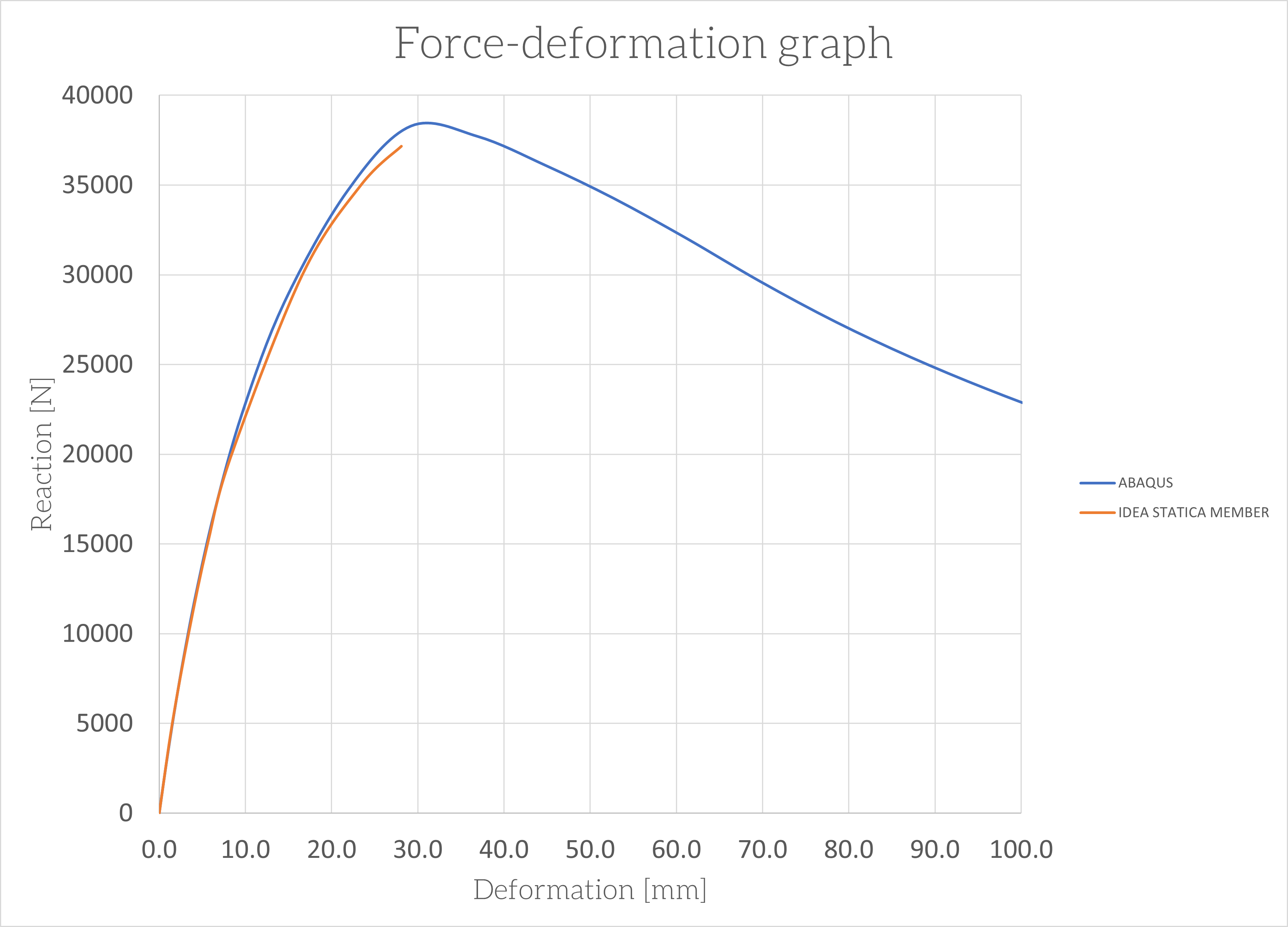
The methodology employed by IDEA StatiCa to solve the equilibrium is based on the Newton-Rhapson method. The analysis is terminated upon reaching the peak point, and the descending branch is unresolved. Nevertheless, this is not deemed necessary for structural engineers, whose primary concern is obtaining a stable solution rather than an unstable one.
12) Load deformation curve IDEA StatiCa (left), ABAQUS(right)
The initial state for GMNIA is based on the shape derived from the buckling analysis. In our case, the first mode shape is a half-sinusoidal wave.
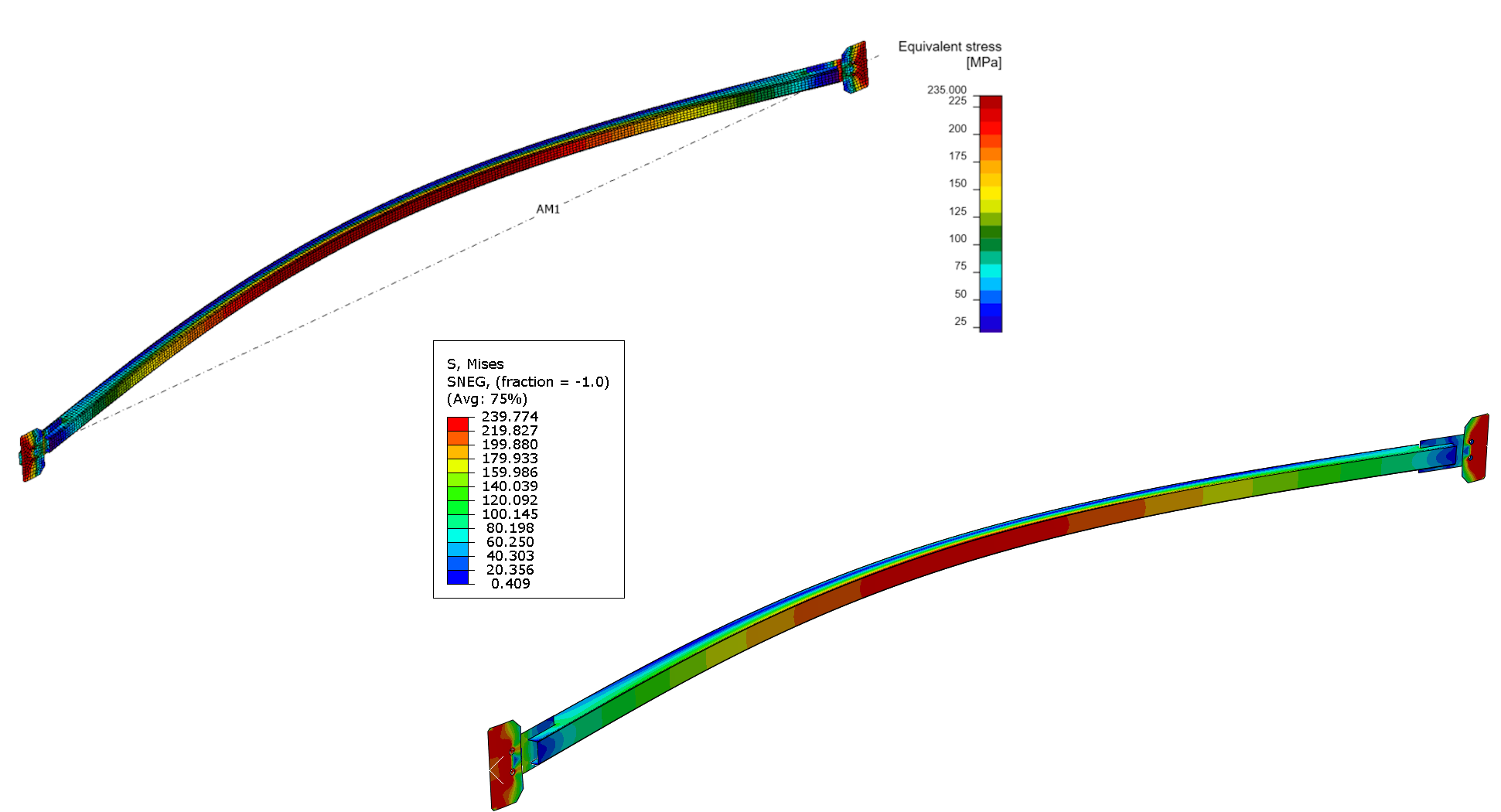
Equivalent stress
The stress levels have escalated to a significant extent, almost reaching the yield point. This indicates that certain components are on the verge of yielding, rendering the IDEA StatiCa model in a plastic state.
13) IDEA StatiCa equivalent stress(left), ABAQUS equivalent stress(right)
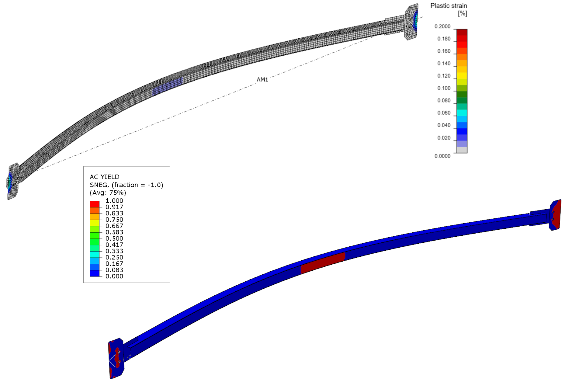
Plastic strain and plastic regions
The spots that have started to yield appeared in the area of connection and in the middle of the bracing itself.
14) IDEA StatiCa plastic strain(left), ABAQUS plastic strain(right)
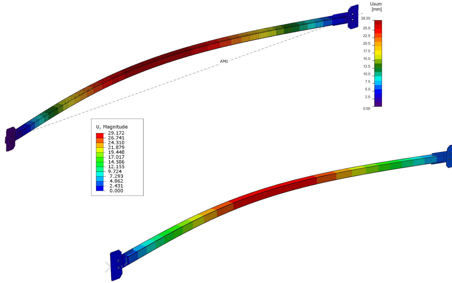
Deformation
Force-deformation graph
Conclusion
During the verification process, the main objective was to showcase the capabilities of IDEA StatiCa Member in ensuring the safe design and code-check of various structures. The tool was thoroughly tested and evaluated to determine its effectiveness in delivering accurate results while adhering to industry standards. The verification aimed to provide a comprehensive understanding of the tool's features and benefits, including its ability to optimize the design process and reduce errors. During the verification process, the main objective was to showcase the capabilities of IDEA StatiCa Member in ensuring the safe design and code-check of various structures. The tool was thoroughly tested and evaluated to determine its effectiveness in delivering accurate results while adhering to industry standards. The verification aimed to provide a comprehensive understanding of the tool's features and benefits, including its ability to optimize the design process and reduce errors.
The comparison between the analytical solution and IDEA StatiCa Member, as well as the ABAQUS solution, yielded a 95% match in results. The maximum design value obtained during the design process was 35.8 kN. However, the critical design value increased to 37.1 kN when using IDEA StatiCa Member, while ABAQUS displayed a maximum value of 38.2 kN. These findings are notable as they demonstrate the efficacy of these design approaches in achieving accurate results.
The results for equivalent stress, plasticity, and deformations are consistent across various applications, indicating the reliability of the code evaluation. These results demonstrate the code's accuracy and robustness for predicting a system response. Their consistency makes the code suitable for use in business and academic settings.


