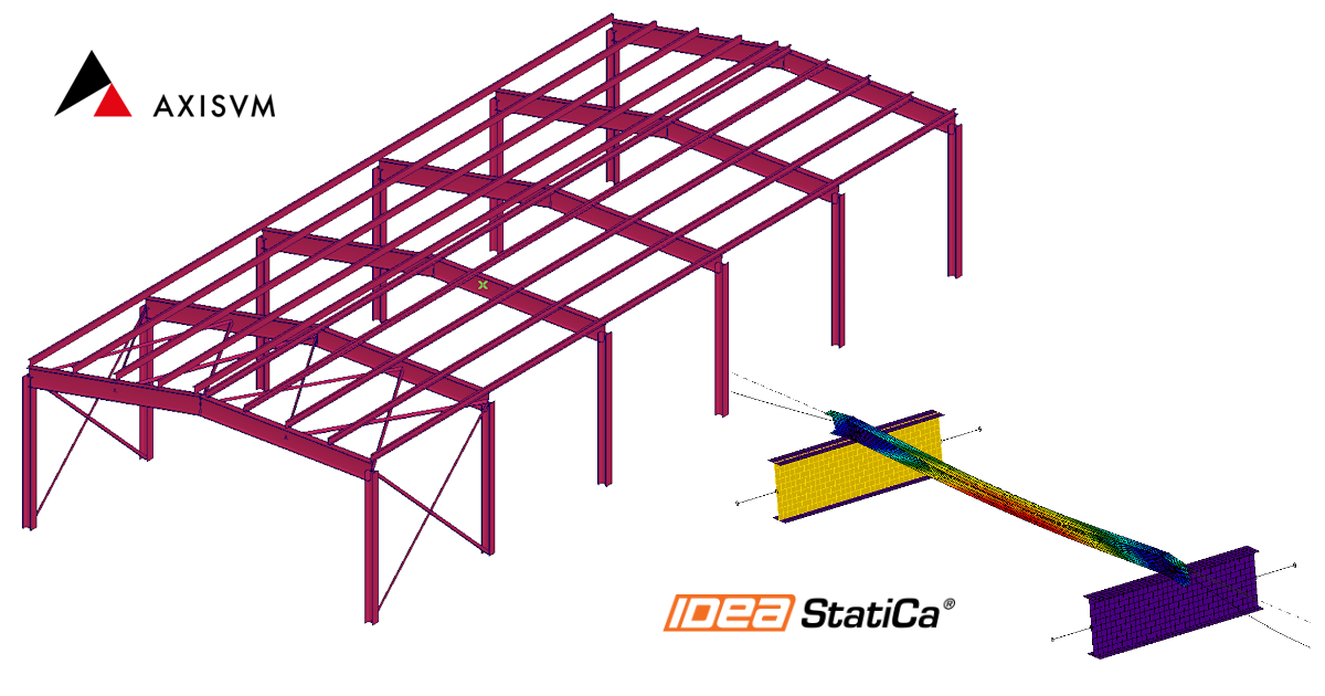
AxisVM BIM link for steel Member design (EN)
Hoe activeer je de link.
- Download en installeer de laatste versie van IDEA StatiCa
- Zorg ervoor dat u een ondersteunde versie van uw FEA/BIM-oplossing gebruikt.
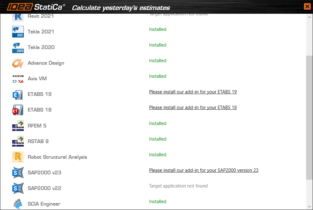
IDEA StatiCa integreert BIM-links in uw FEA/BIM-oplossingen tijdens de installatie ervan. U kunt de status controleren en meer BIM links activeren voor software die na de installering in de BIM link installer is opgenomen.
Houd er rekening mee dat sommige FEA-oplossingen extra stappen vereisen om de BIM-link met IDEA StatiCa volledig te activeren.
Open IDEA StatiCa en navigeer naar de BIM tab en open de BIM link installer (Activate your BIM link...).
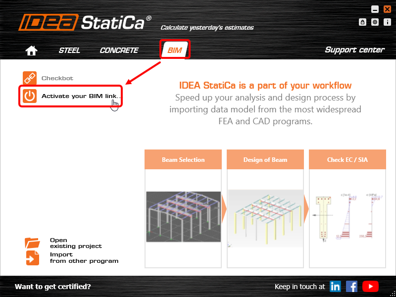
Er kan een melding verschijnen "Wilt u toestaan dat deze app wijzigingen aanbrengt aan uw apparaat?", zo ja, bevestig dan met de Ja-knop.
De BIM-link voor de geselecteerde software (indien gevonden) wordt geïnstalleerd. Het scherm toont ook de status van andere BIM-links die mogelijk al zijn geïnstalleerd.
How to use the link
Download the attached project, open it in AxisVM, and run the calculation to get the internal forces over the structure.
The BIM link is already integrated. It is in the top ribbon under Plugins -> IDEA StatiCa Checkbot.

Consequently, Checkbot application will be started.
Select the New option with project type Steel and design code EN. Then select Create project.
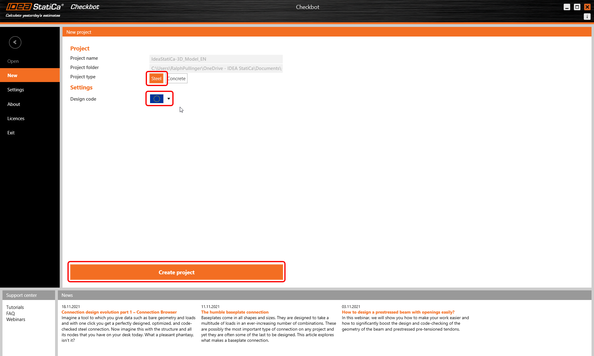
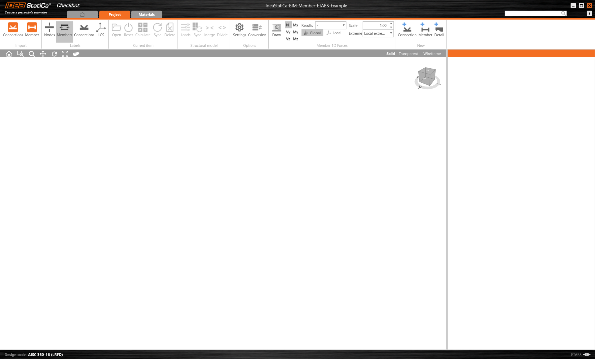
The new Checkbot project is ready to import connections from AxisVM.
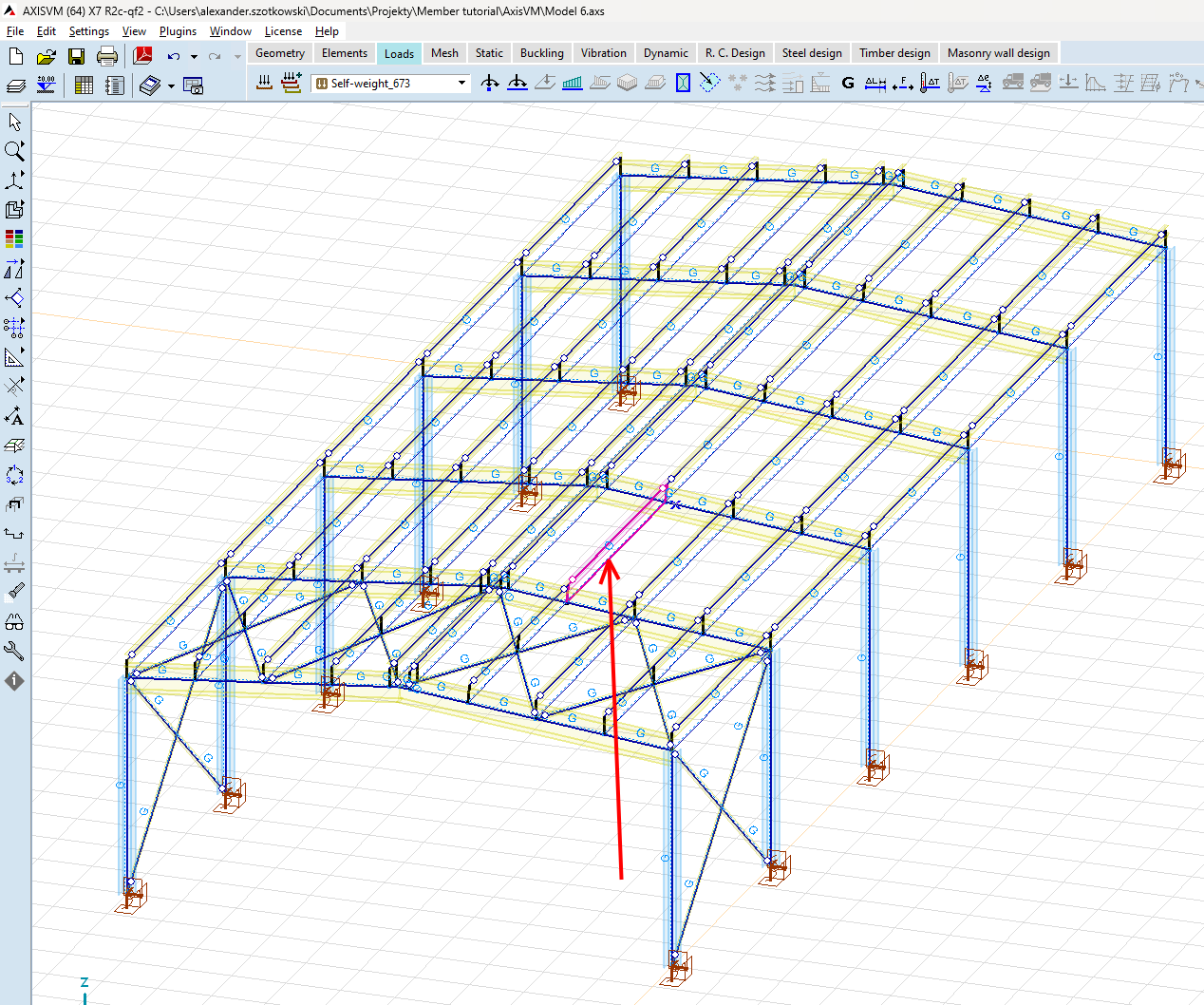
In AxisVM, select one of the inside members, as shown in the picture.
Import
Then in Checkbot select Member.
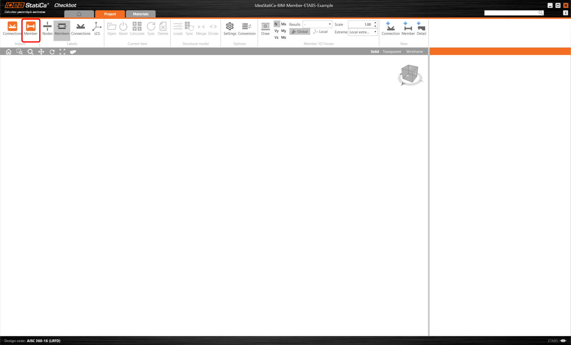
This will import the beam and its load effects into Checkbot - with the exact coordinates, orientations, and section sizes as per the FEA/BIM model.
Please note that your node and member numbering might be different, also the elevation position of the member itself.
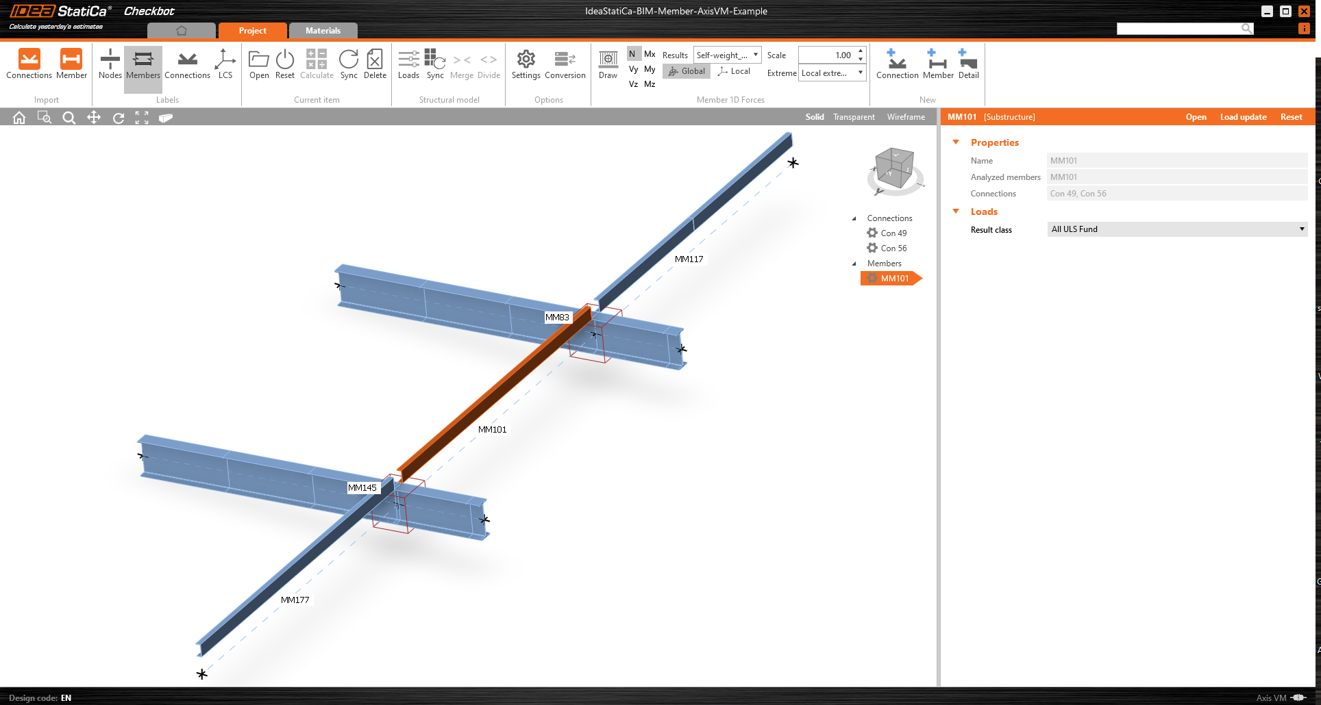
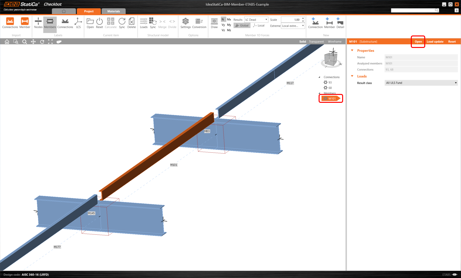
As you can see, the selected member with all related members was imported.
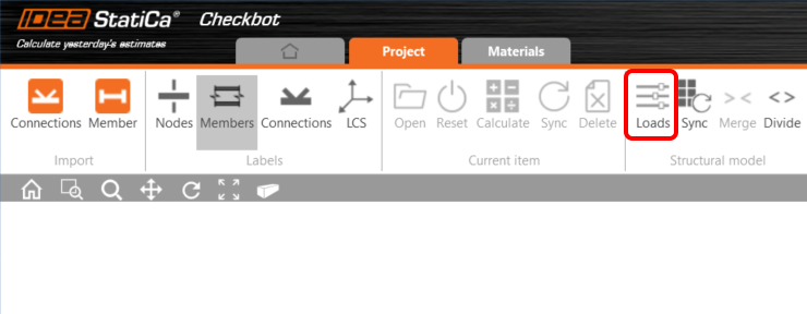
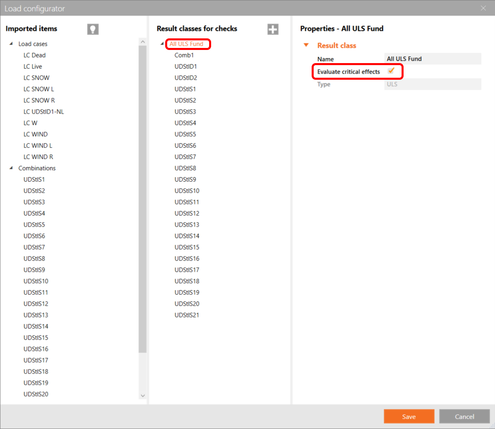
You can control what load case or combination will be loaded to the Member application by clicking on Loads and managing Result classes for checks.
Here in Load Configurator, you can add load cases for the member application. Please notice by default the Evaluate critical results function is enabled, which filters critical combinations to speed up the calculation. You can turn it off and all combinations will be included in the calculation.
Maak vandaag nog een proefrit met de nieuwste IDEA StatiCa
Members modul
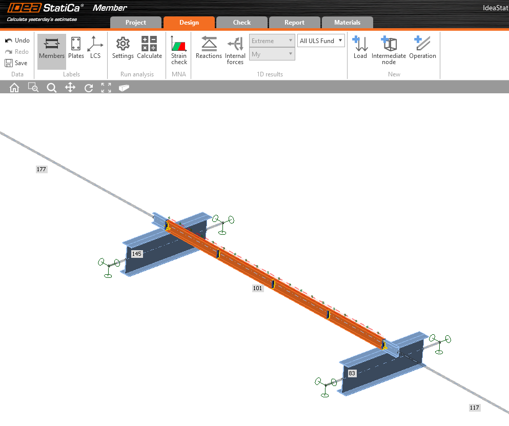
Now we can open the Member application. Just left-click on Open.
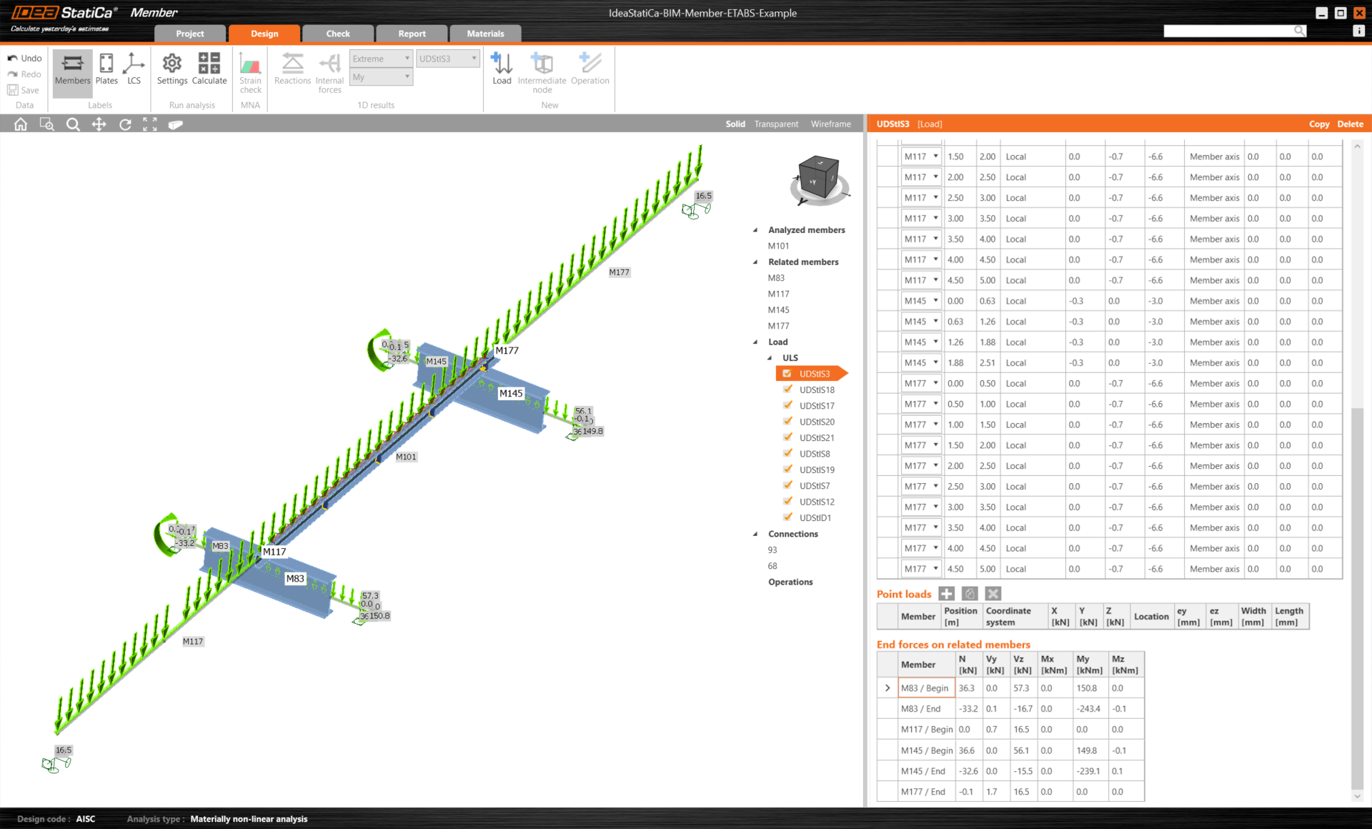
Here you can see our Member application.
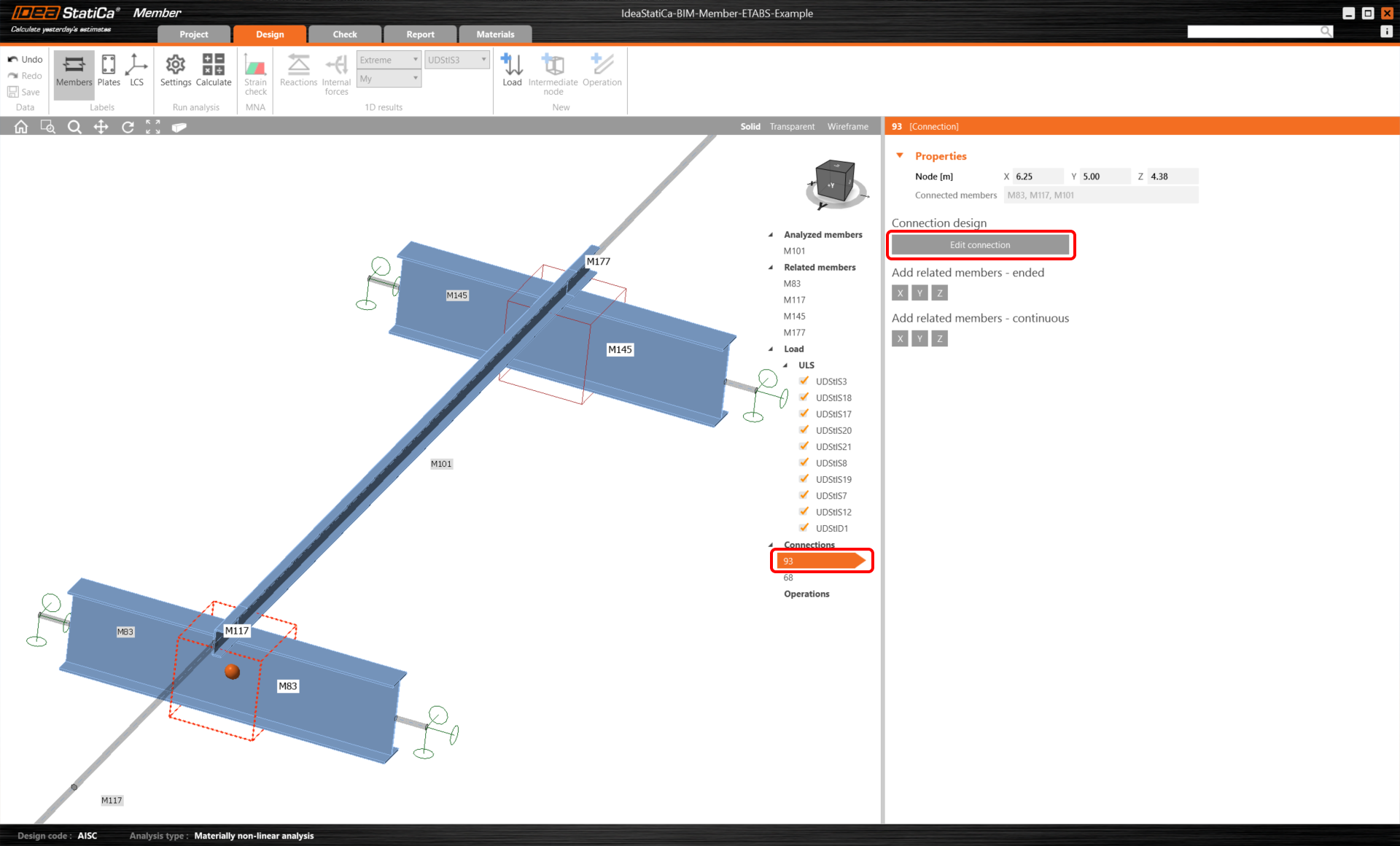
In the beginning, let us design the joints of the member U-profile, so please select the first connection and click on Edit connection. As you can see now I-profiles are represented by one continuous element, thanks to the merging we made.
Connections design
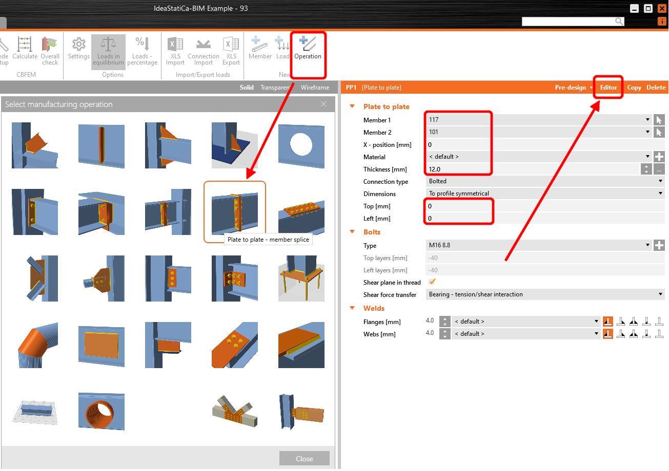
Click on Operation and select Plate to plate. Change the values according to the picture, then click on Editor.
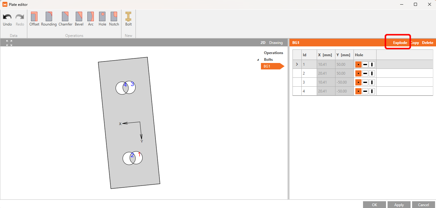
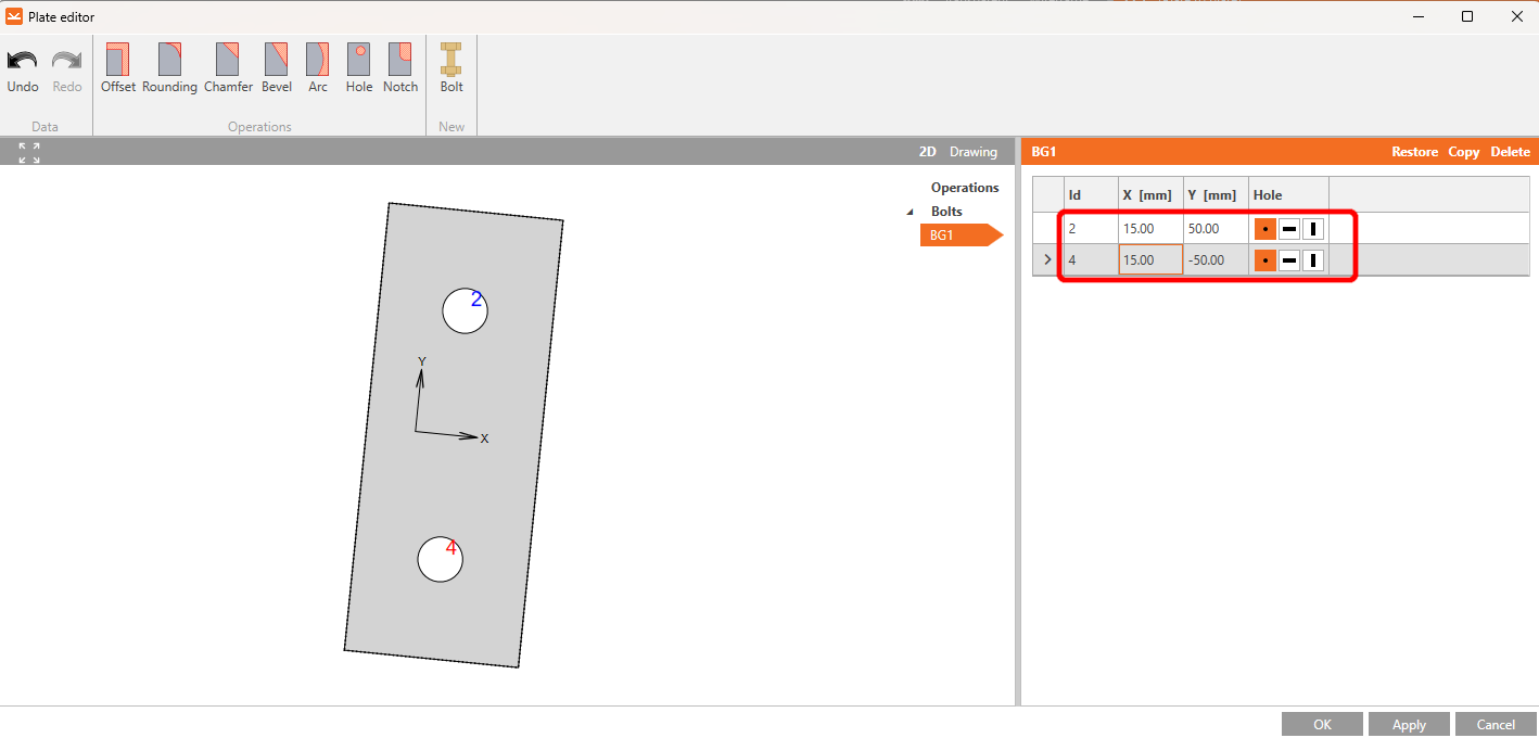
Click on Explode, delete the bolts Nr. 1 and 3, and set the values for bolts Nr.2 and 4 according to the picture.
After you make the changes, the element should look like this. Continue by clicking ok.
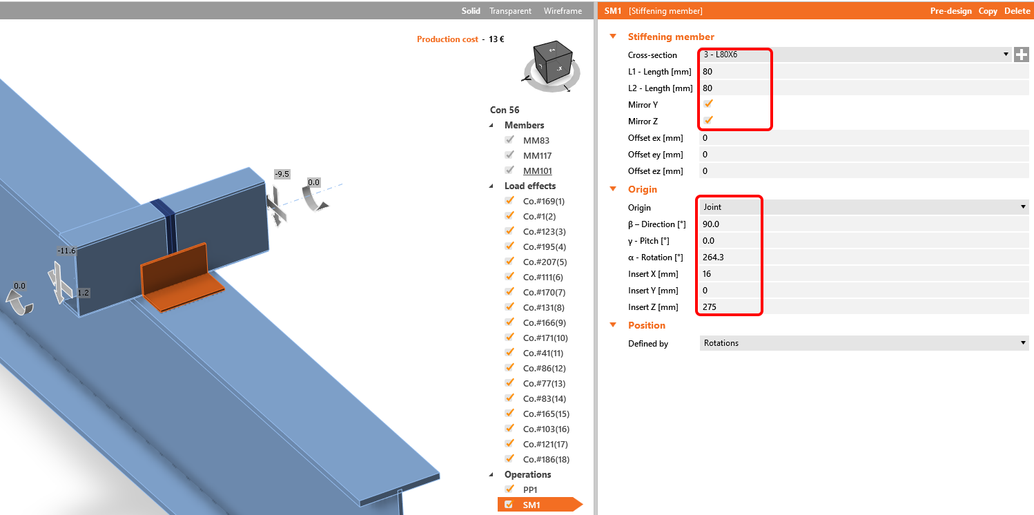
The next operation is the Stiffening member. First, you need to add a new L80x6 cross-section, click the white cross in the cross-section row, select L-profile, and enter the necessary name in the search. After that, fill in the values as shown in the following picture. Consequently, our model should look as shown in the picture below.
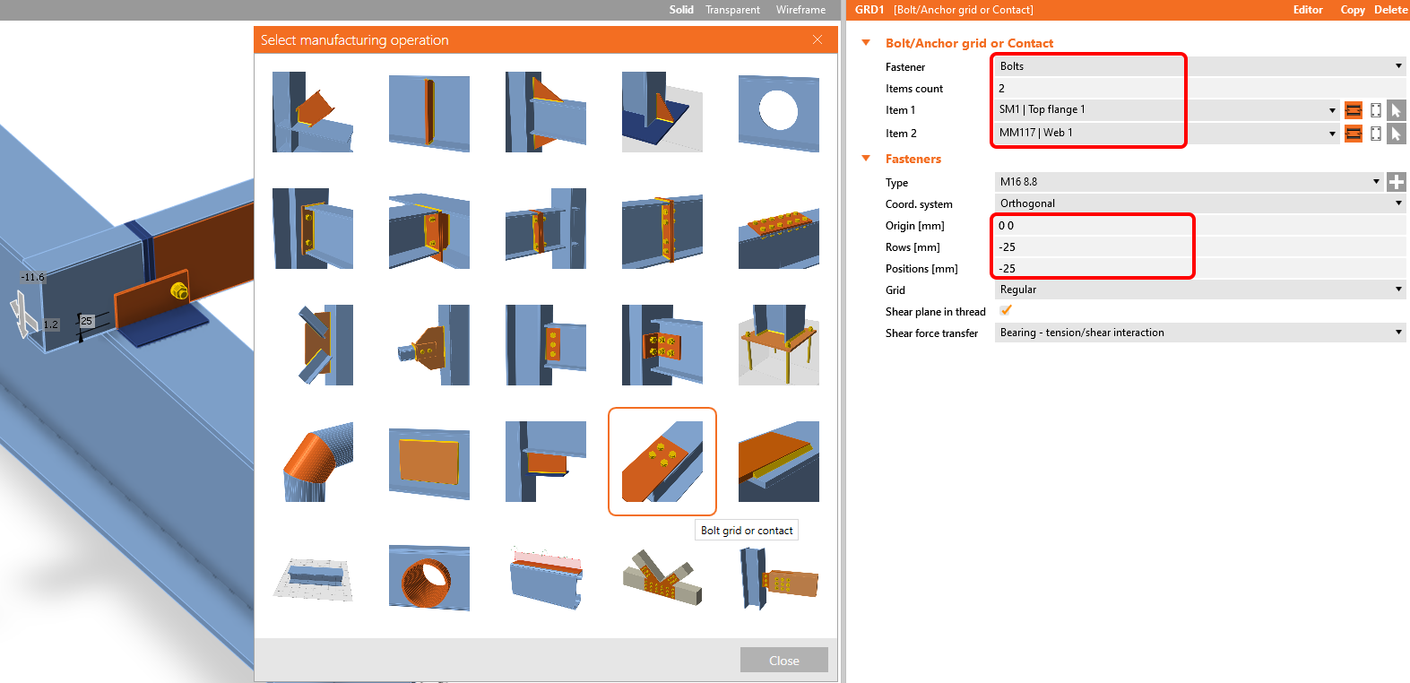
Add the operation Bolt/Anchor grid.
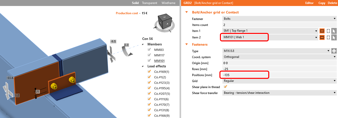
Copy this operation and change the selected values.
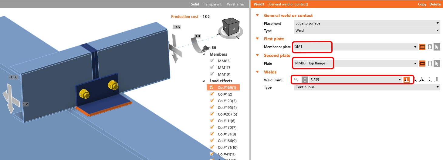
Add a weld to connect SM1 with the upper flange.
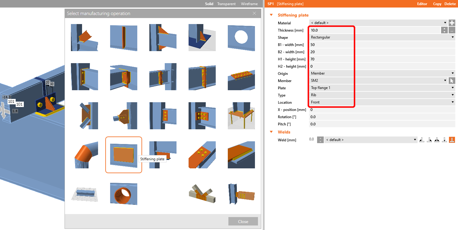
Now add a Stiffening plate to the joint and set the values according to the picture.
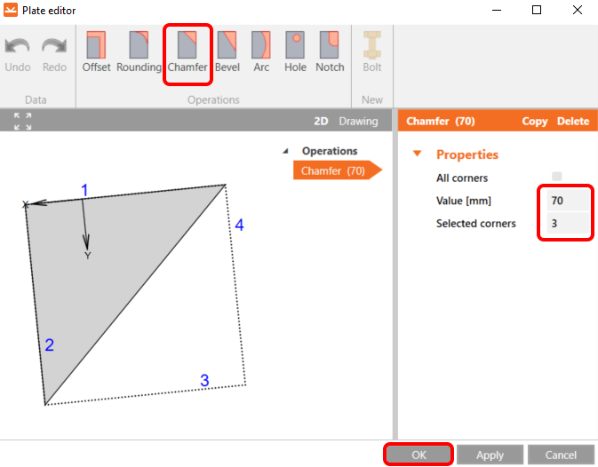
Then go to the Editor, select the chamfer operation, and set it according to the image.
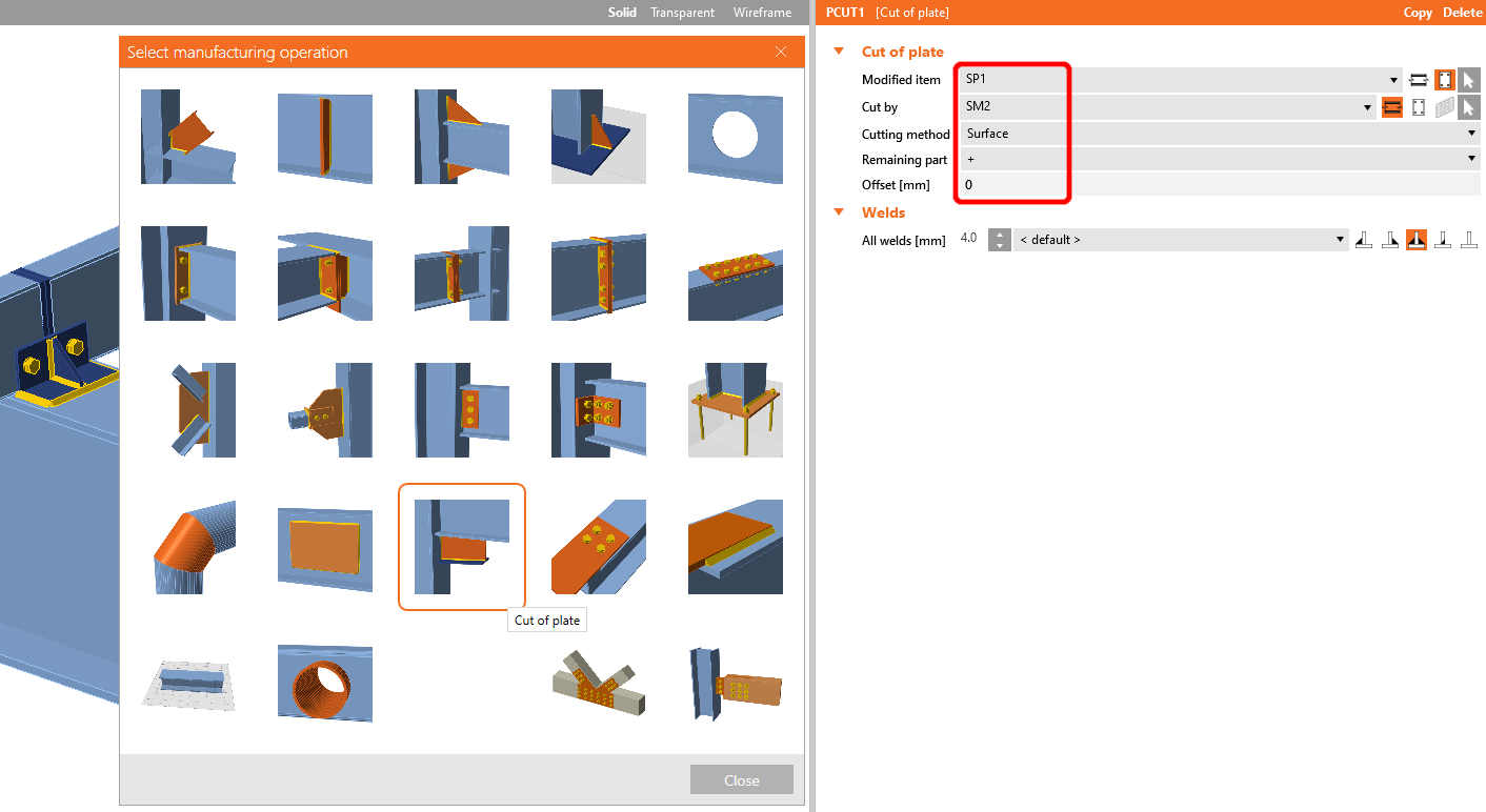
The last operation is Cut of plate operation.
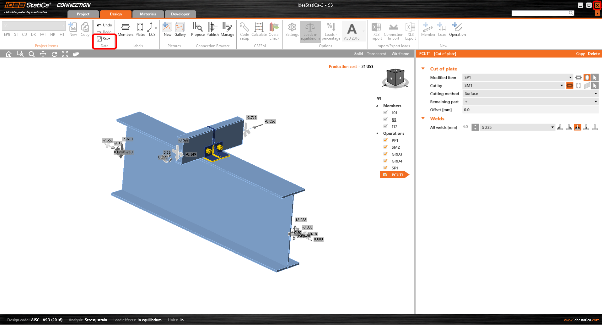
Now click on Save and close the module Connection.
Maak vandaag nog een proefrit met de nieuwste IDEA StatiCa
Check and Control
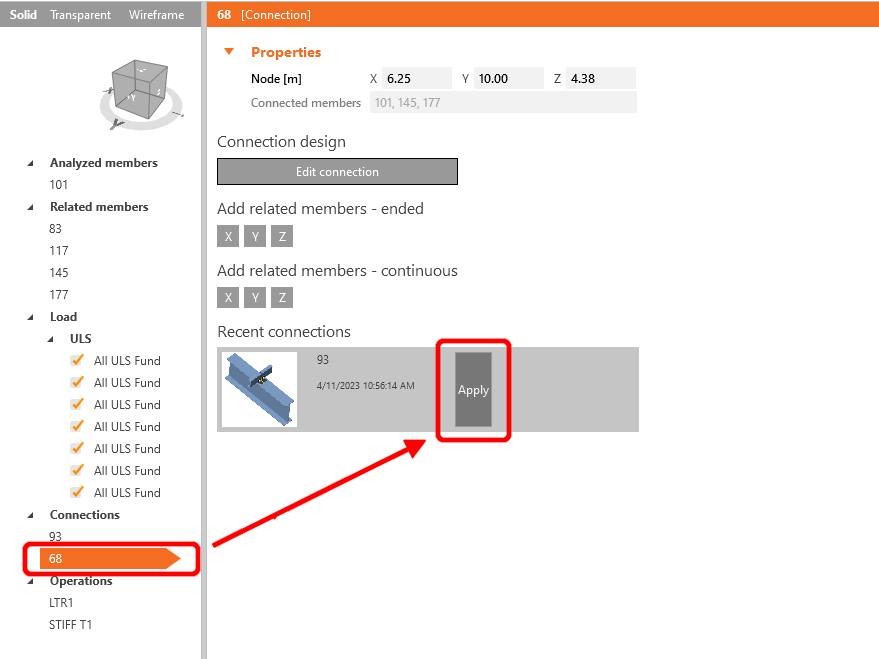
As we have similar joints on both sides of the member, you can copy the operations from the first joint to another by clicking Apply.
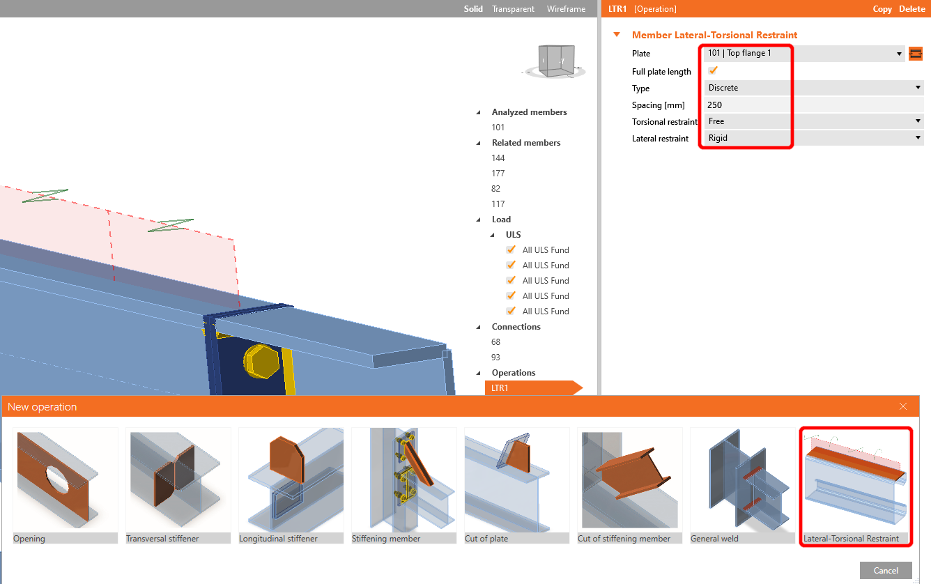
Before starting the analysis, firstly left-click on the U-member, add operation Lateral Restraint, and set up the values according to the picture.
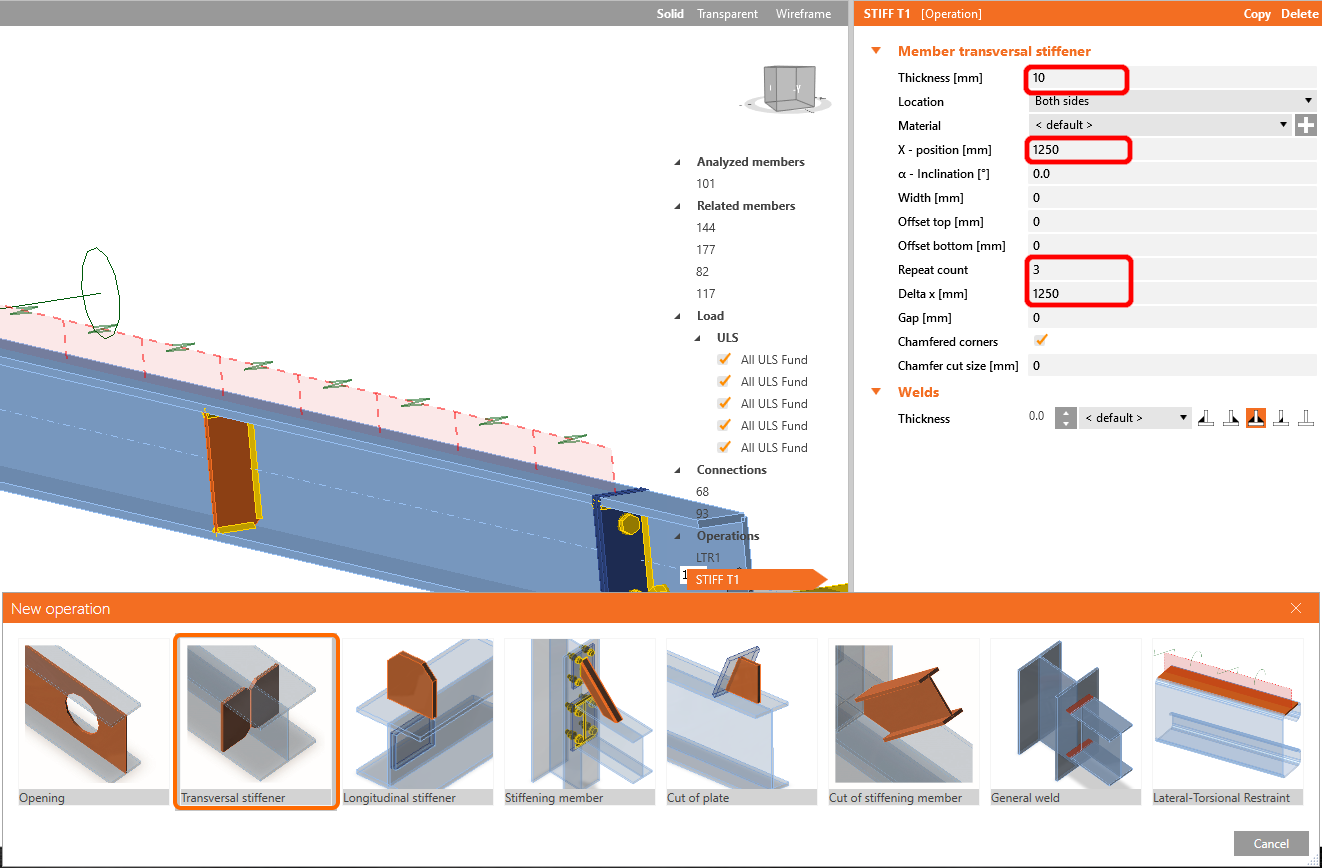
In the next step add operation Stiffeners the same way as in the previous step, and configure the values as shown
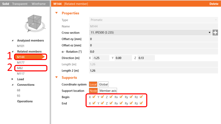
For the realistic behavior of the related members, restrict the supports of the connecting purlins to X, Y, Z, and Rx.
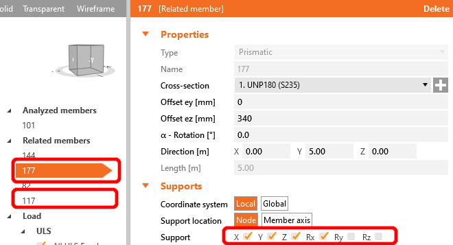
Do the same for the I-profiles frame members; restrict them to X, Y, Z, and Rx, Ry, Rz.
Now the member is ready to be analyzed.
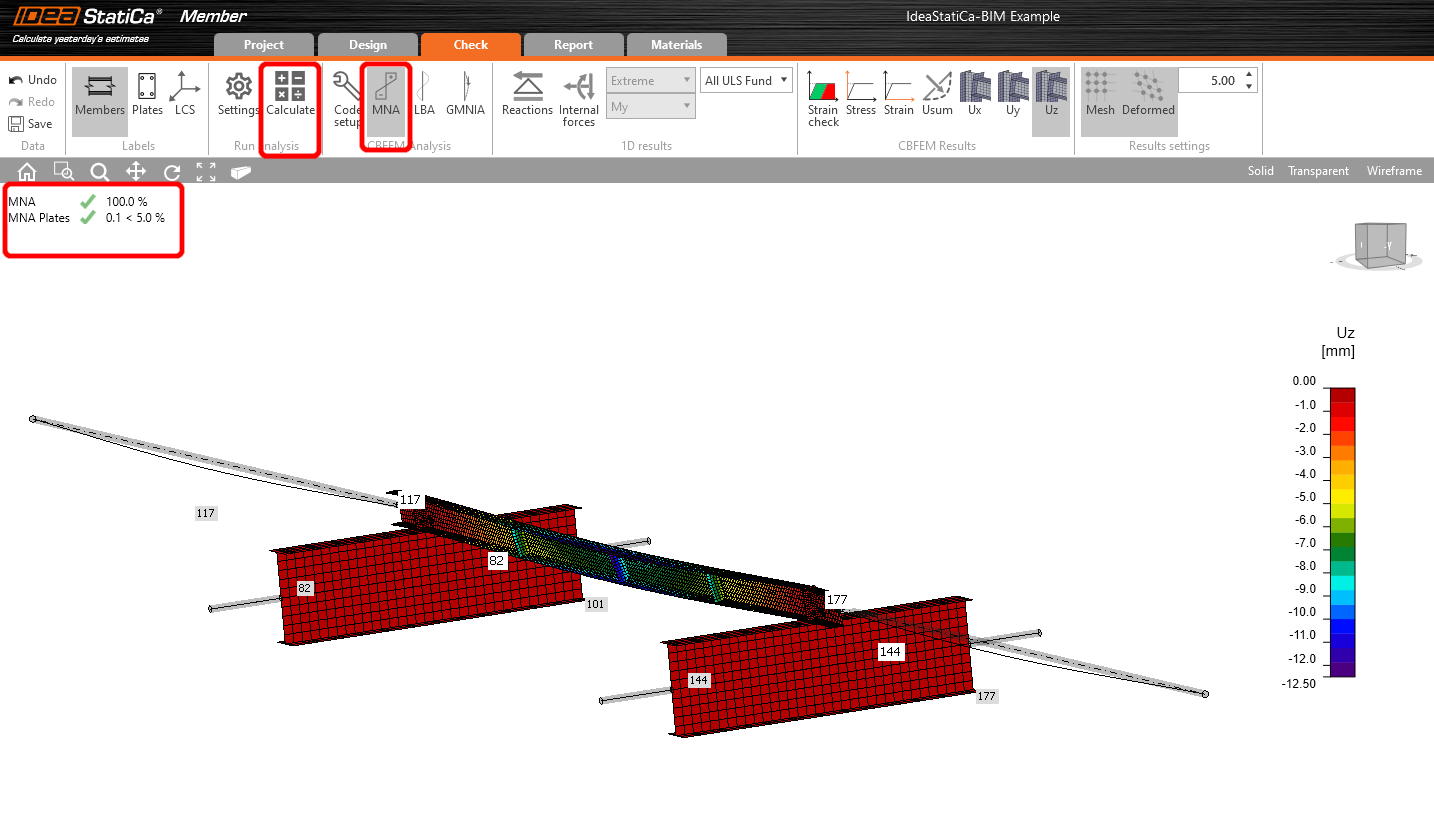
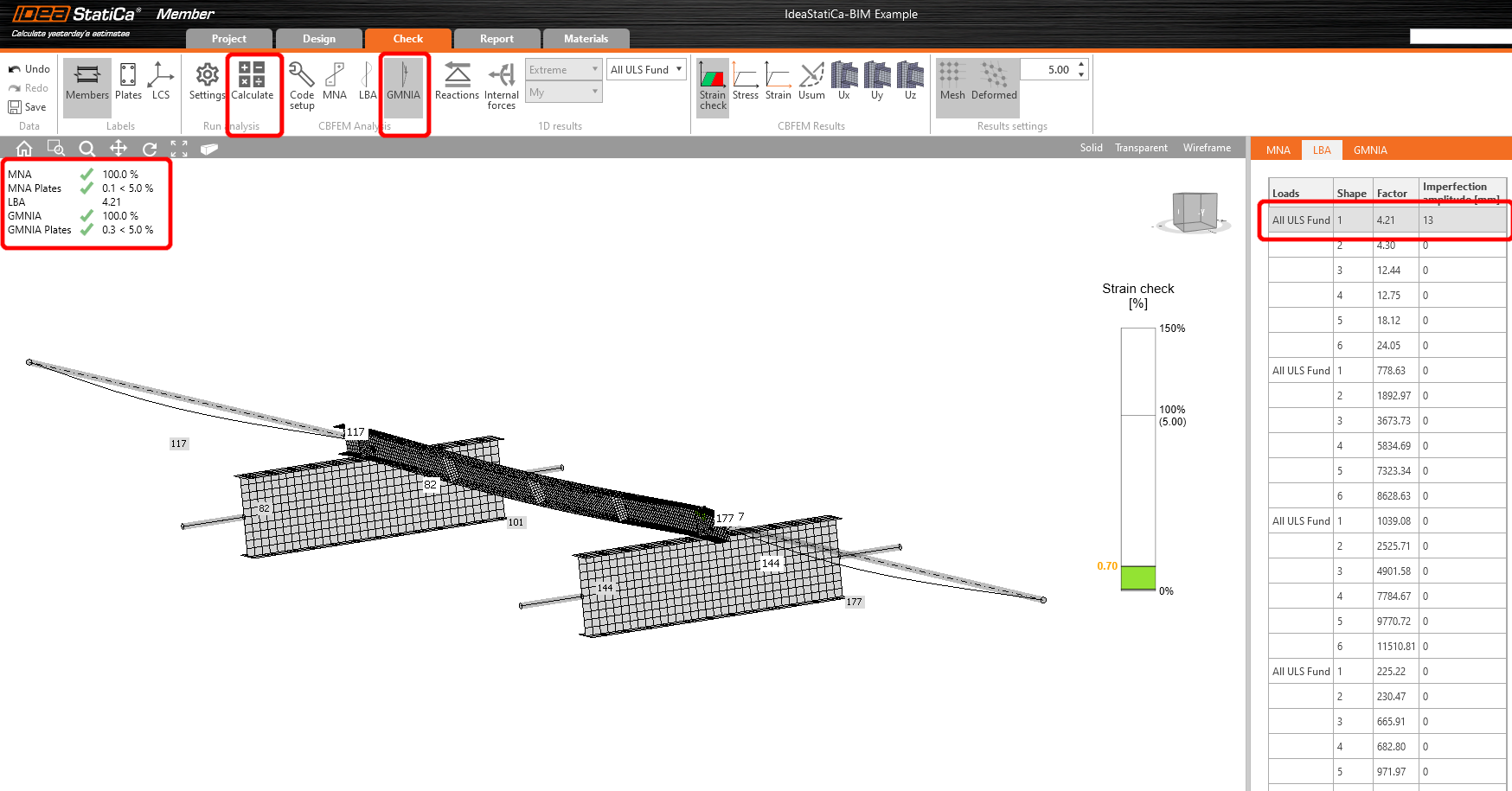
Select the Tab Check and run the MNA (materially non-linear) Analysis.
The second analysis is LBA (lateral buckling analysis), where we get a critical factor of less than 15.
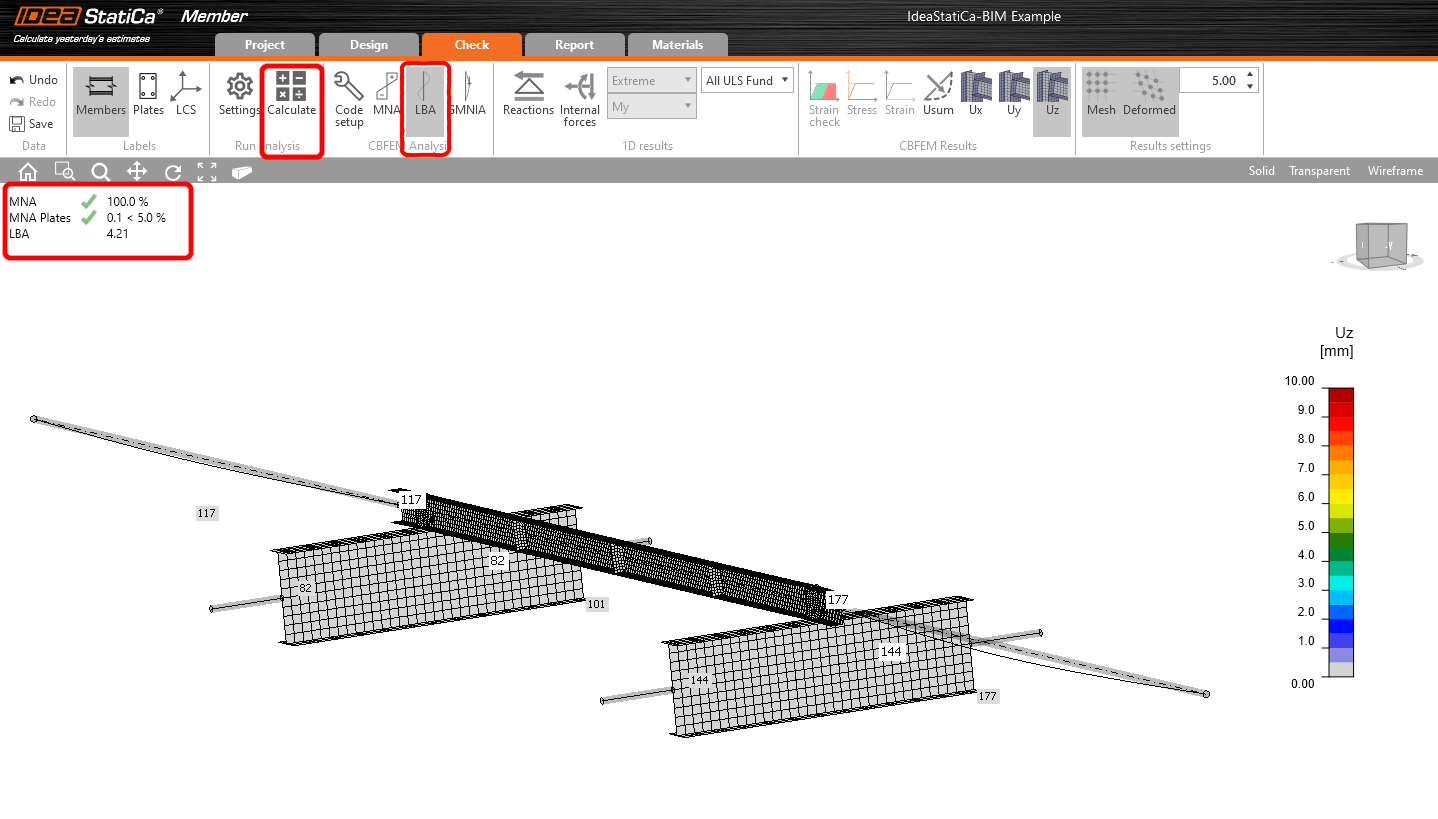
This result shows the necessity of running the GMNIA (geometrically and materially non-linear analysis).
Because lateral-torsional buckling is investigated, factor k0 = 0.5 may be used. Amplitude 0.5 • 5000 / 200 = 12,5 mm is applied to the first buckling mode.
Click on the imperfection field for the critical buckling factor, and fill the value we calculated above in the row, as shown in the following picture. Then you can run the last GMNIA (geometrically and materially non-linear) analysis.
Read more about:
- Member stability in IDEA StatiCa Member.
- Lateral torsional buckling
We have successfully imported and checked a purlin from AxisVM.
Maak vandaag nog een proefrit met de nieuwste IDEA StatiCa
Toegevoegde downloads
- IdeaStatiCa-BIM-Member-AxisVM-Example.zip (ZIP, 1,4 MB)
- BIM-Member-AxisVM-Example.axs (AXS, 104 kB)