
Structural design of a footing with diagonal (AISC)
1 New project
Let’s launch IDEA StatiCa and select application Connection. Create a new project by selecting a starting template closest to the desired design, filling in the name, and choosing the design code and default material properties – A992.
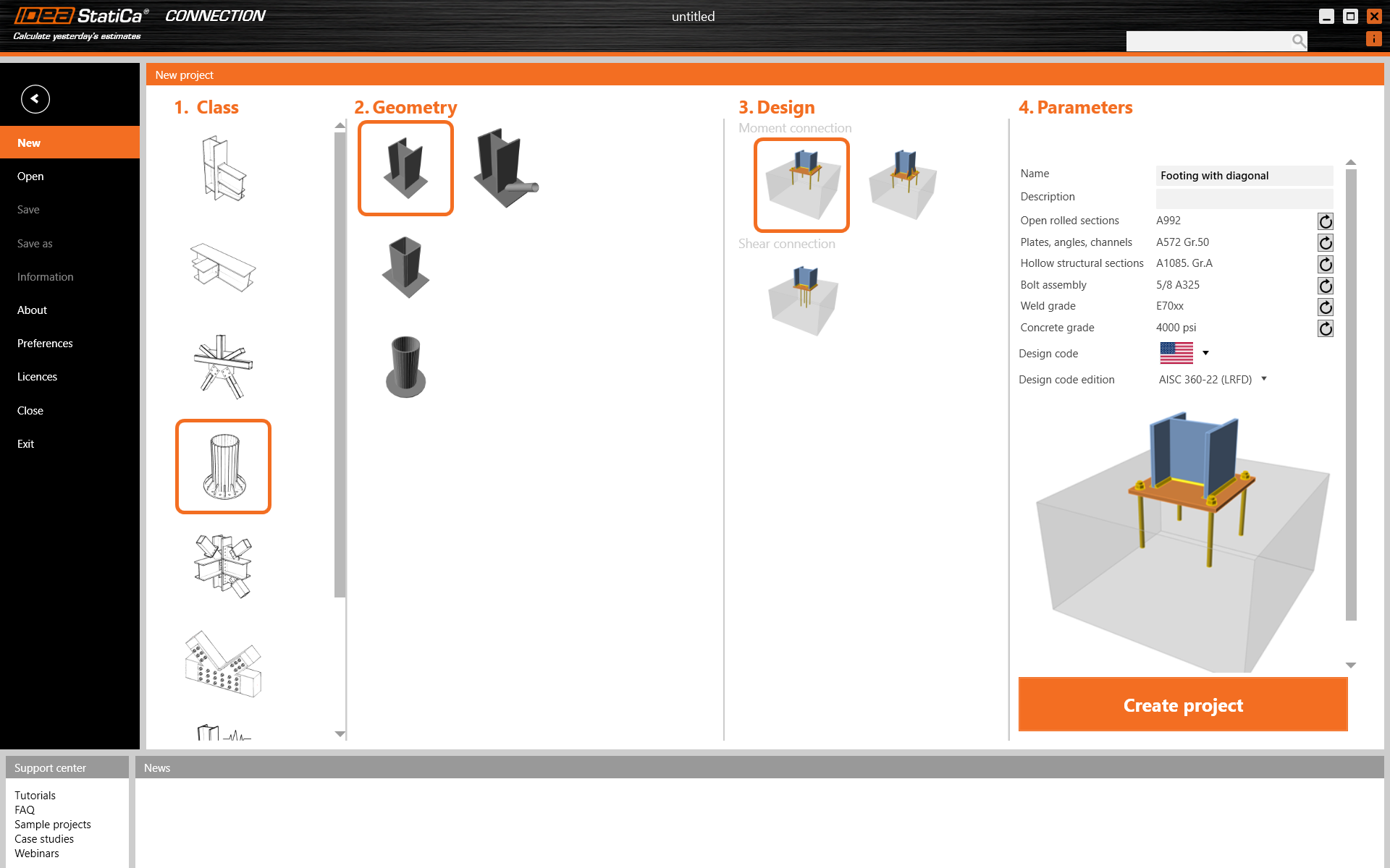
Since you work under the AISC code, set the imperial units (see How to change the system of units).
2 Geometry
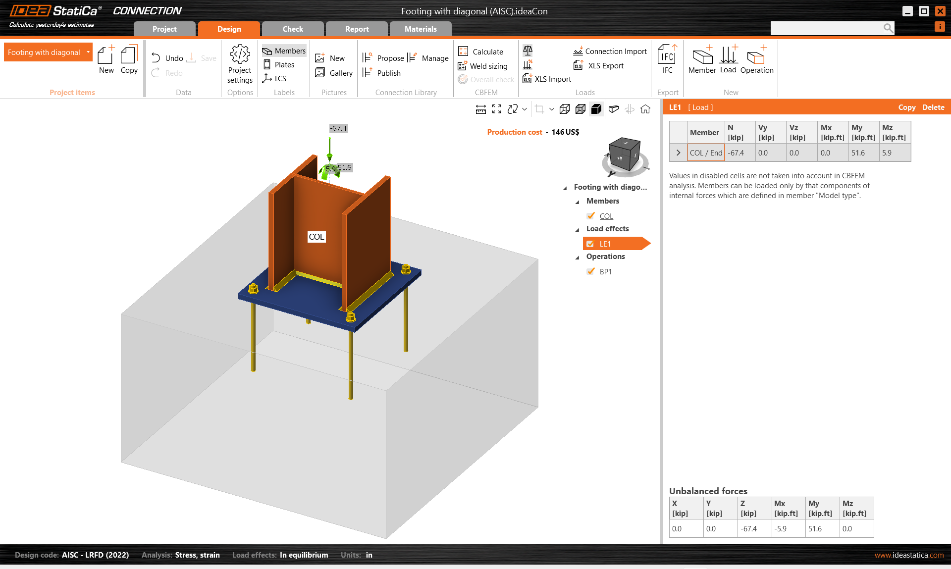
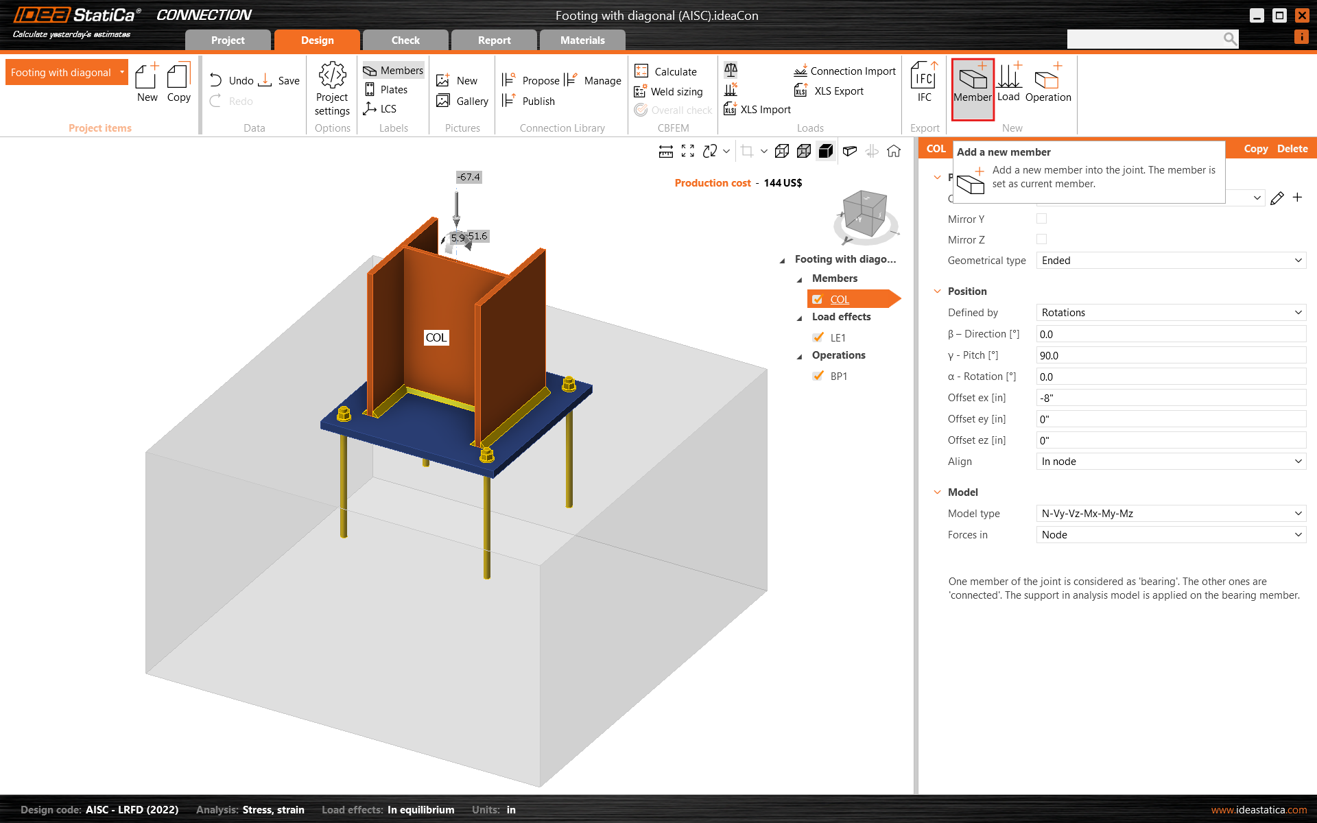
A column and a base plate with anchors were automatically added.
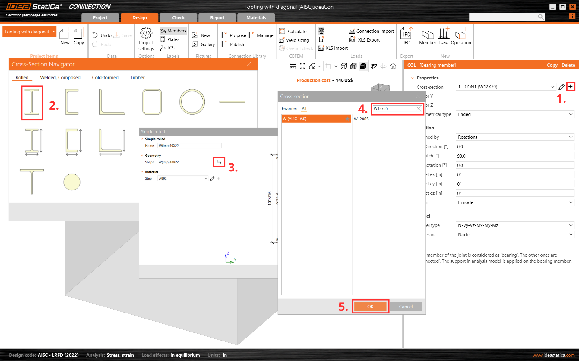
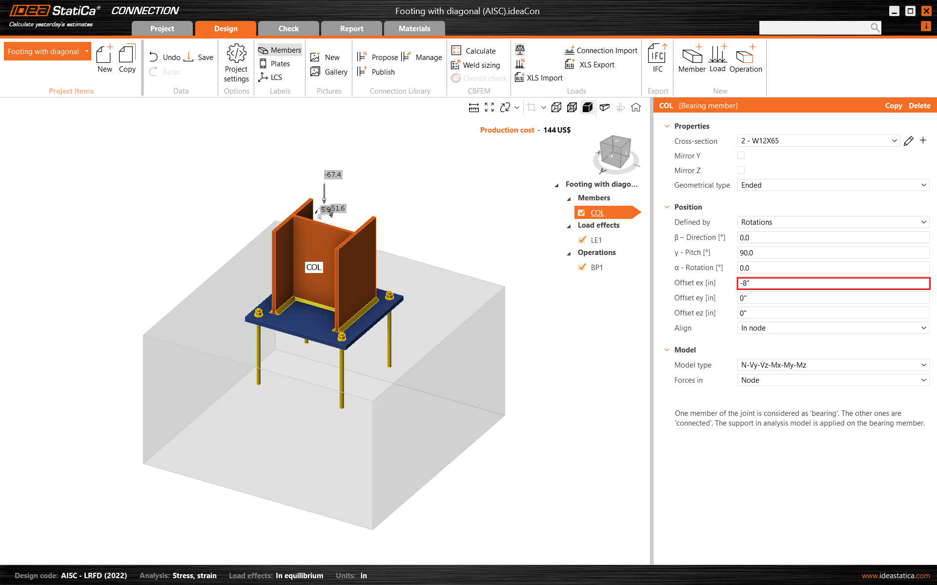
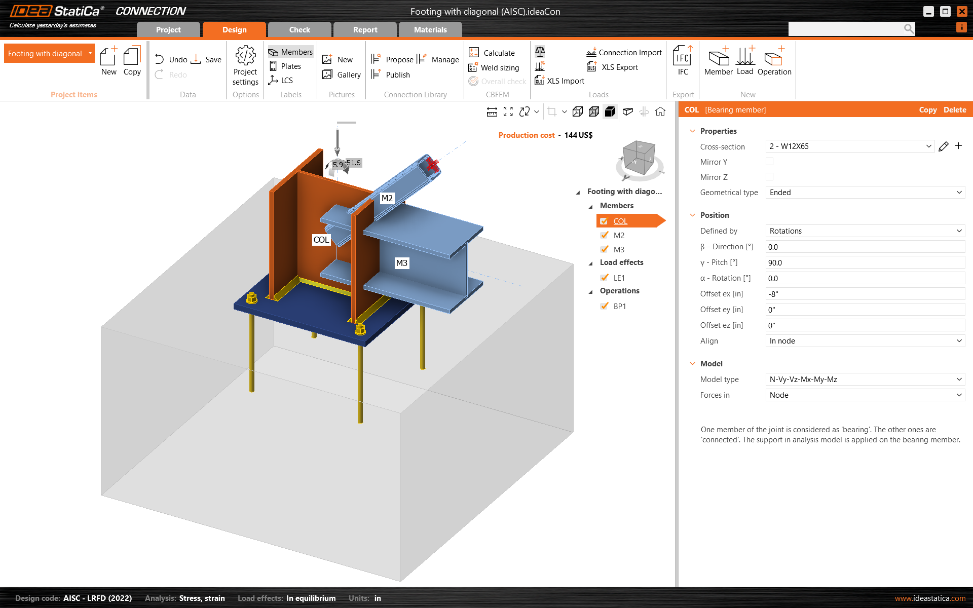
First, change the cross-section of the column.
And modify its offset in ex direction.
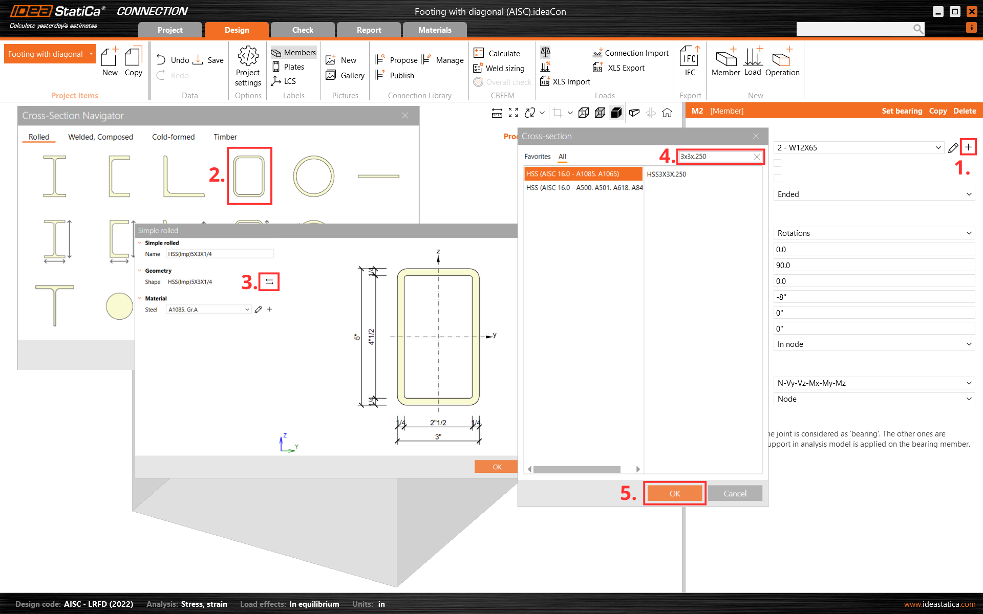
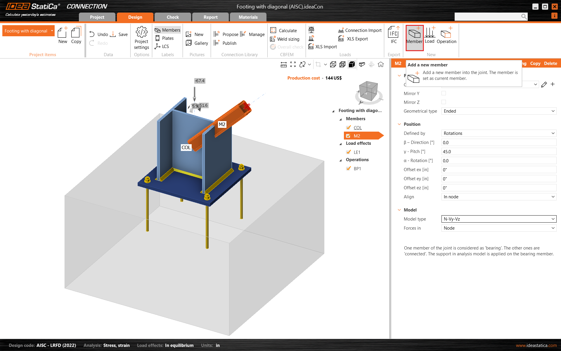
Then add a new member.
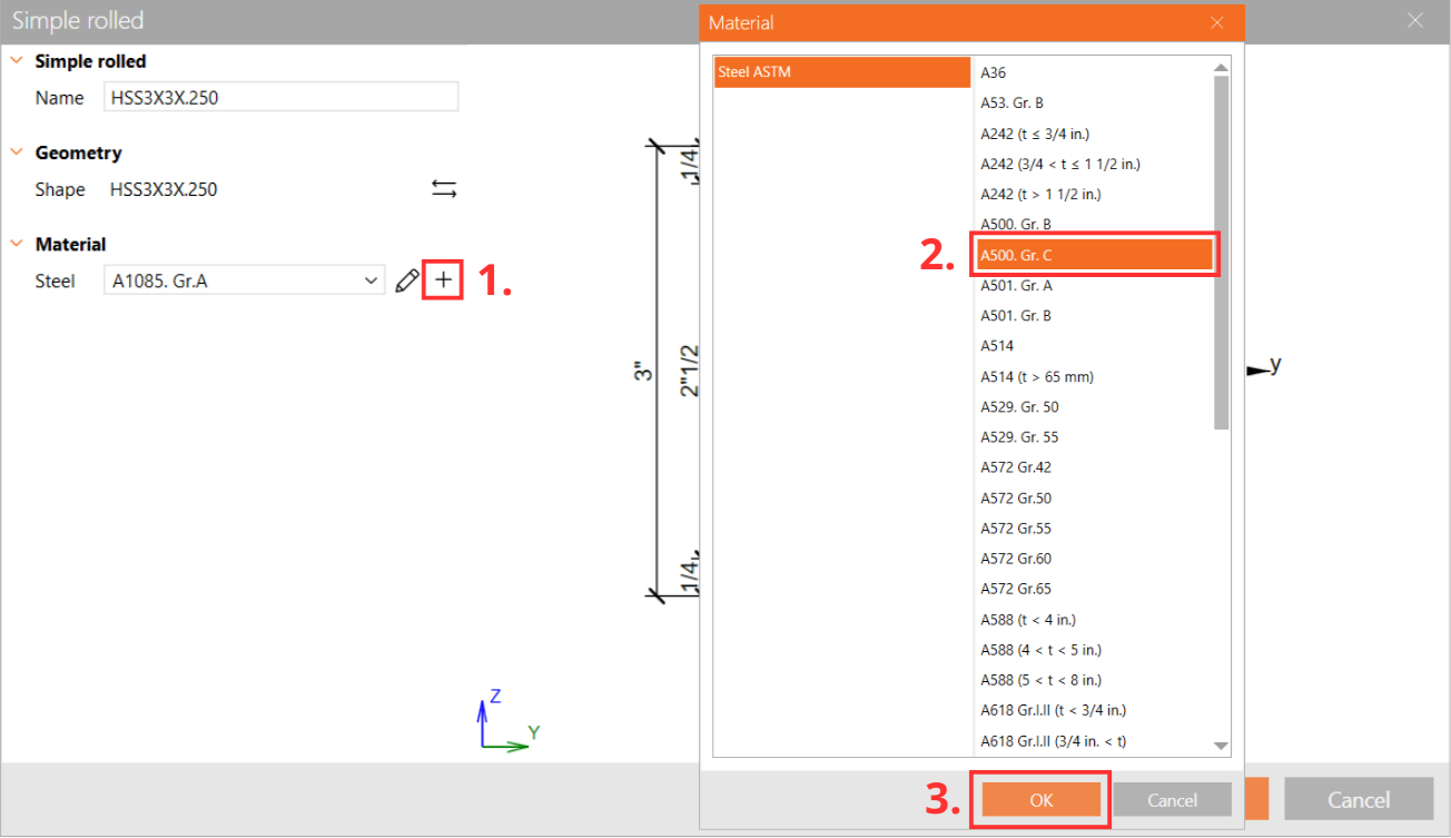
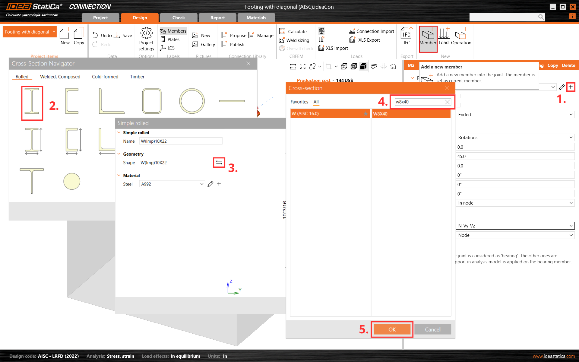
And change its cross-section to HSS3X3X1/4 and material to A500 Grade C shaped
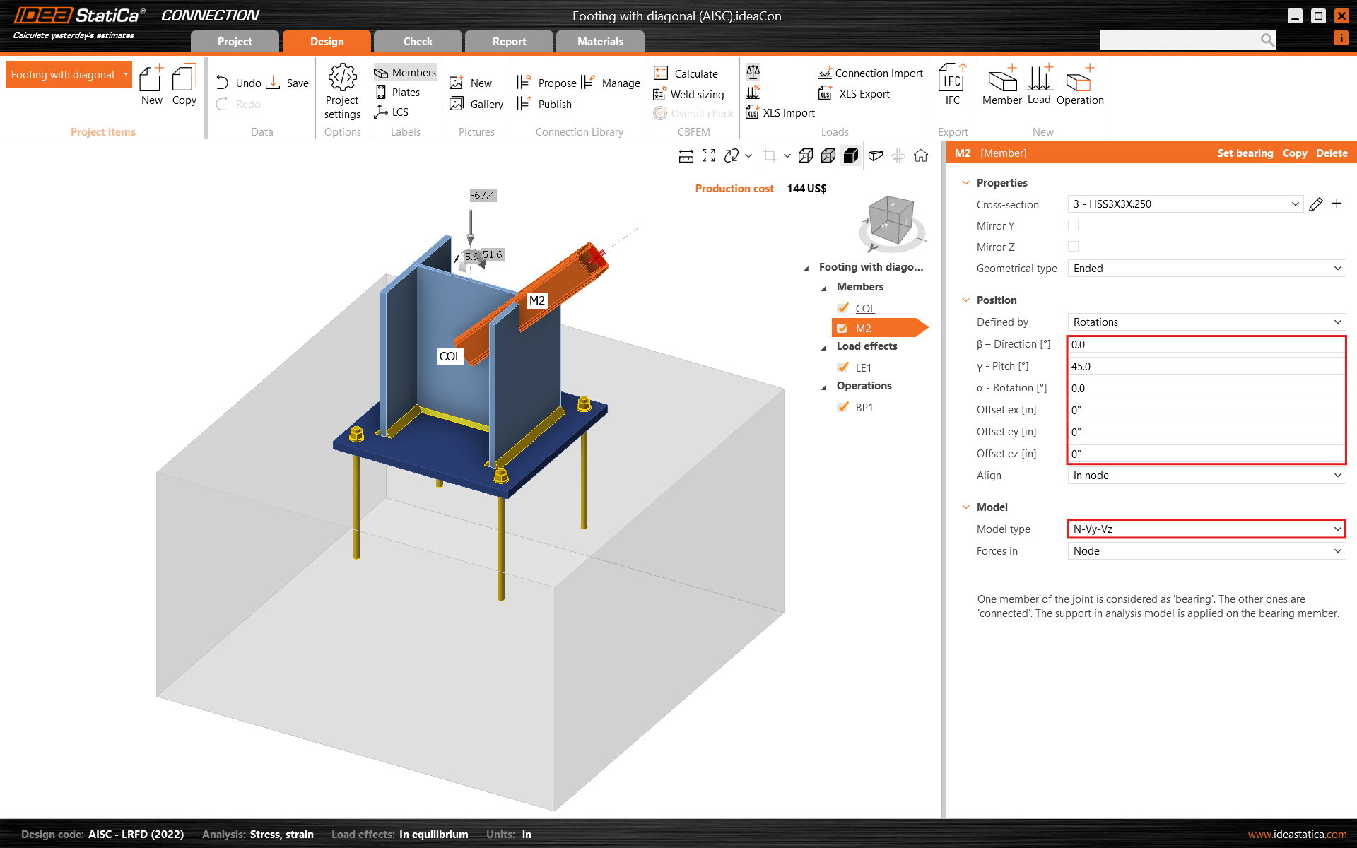
Change the member pitch angle and set the model type to N-Vy-Vz since this member will act in tension/compression only as a pinned bracing diagonal.
Add another member, change its cross-section to W8X40, and modify its properties.
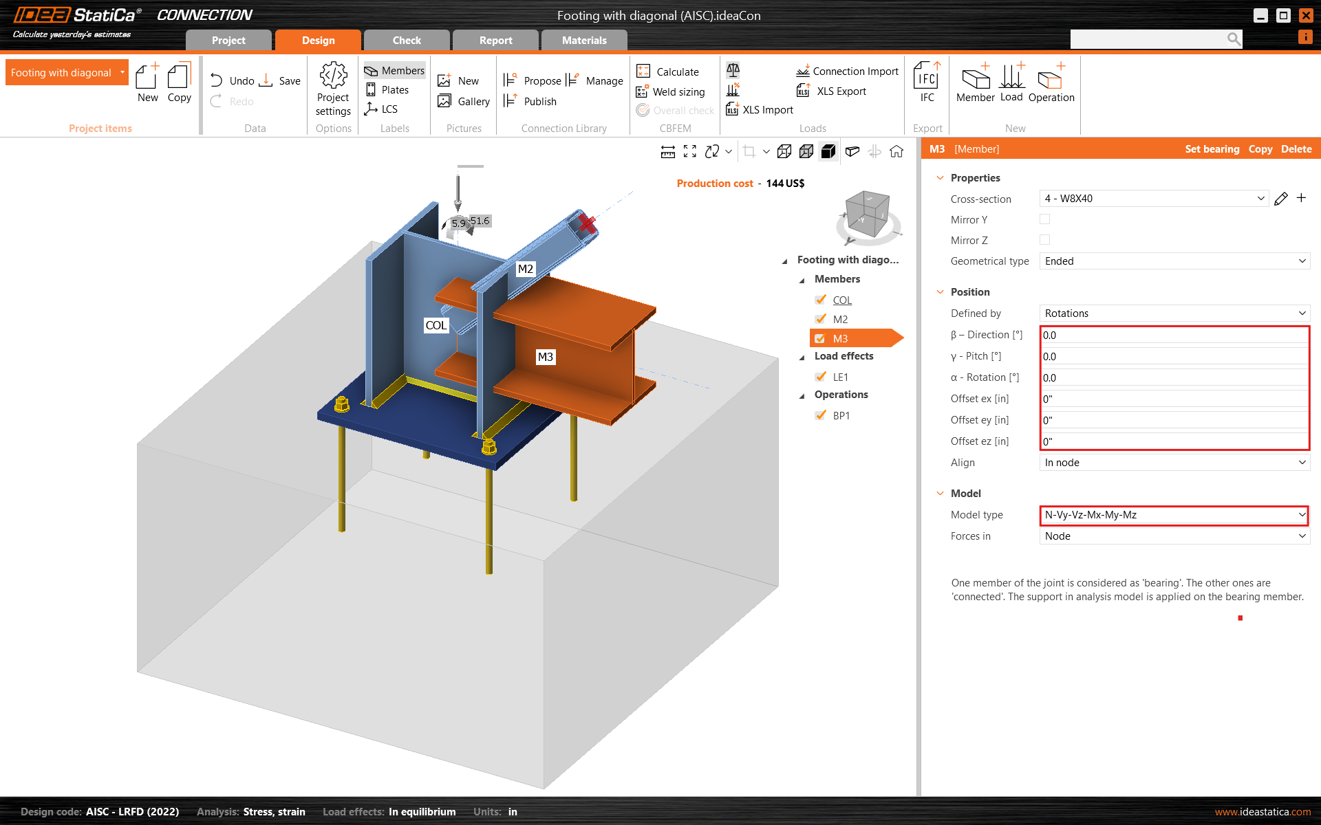
Check the geometry of all added members.
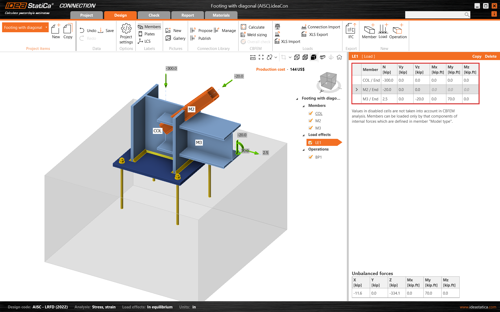
3 Load effects
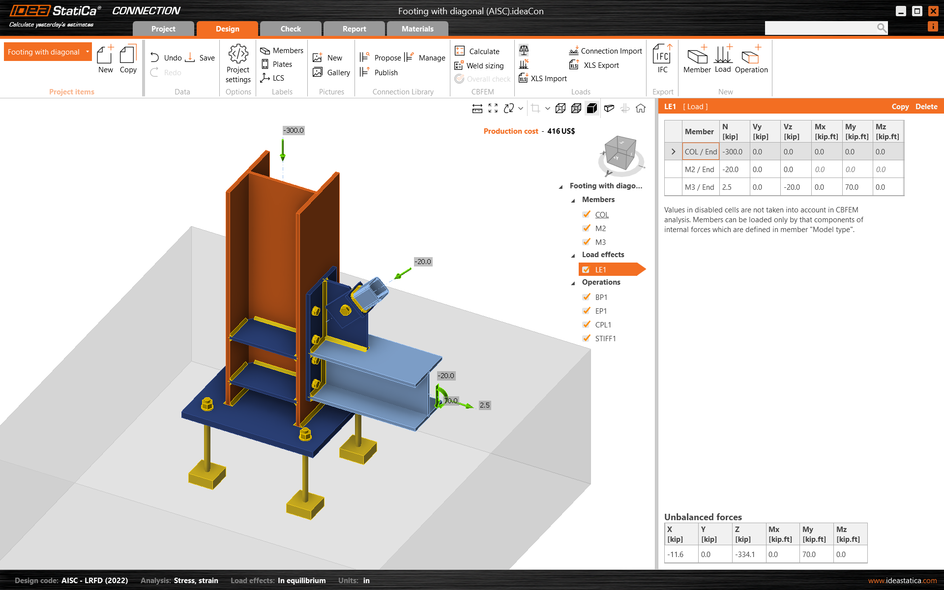
One load effect was automatically added. Input the values of internal forces into the chart. More load cases can be added.
4 Design
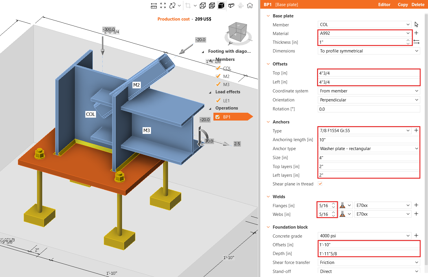
The manufacturing operation Base plate was already added. Just update some of its properties.
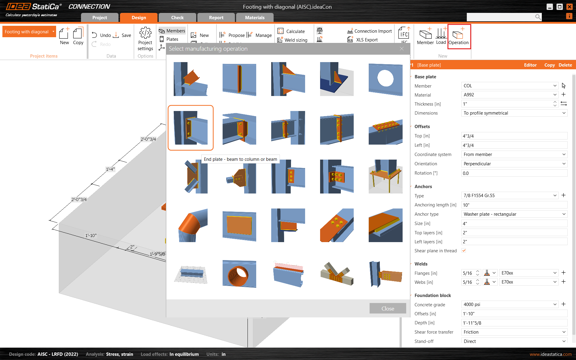
Go on and add another manufacturing operation and select the End Plate.
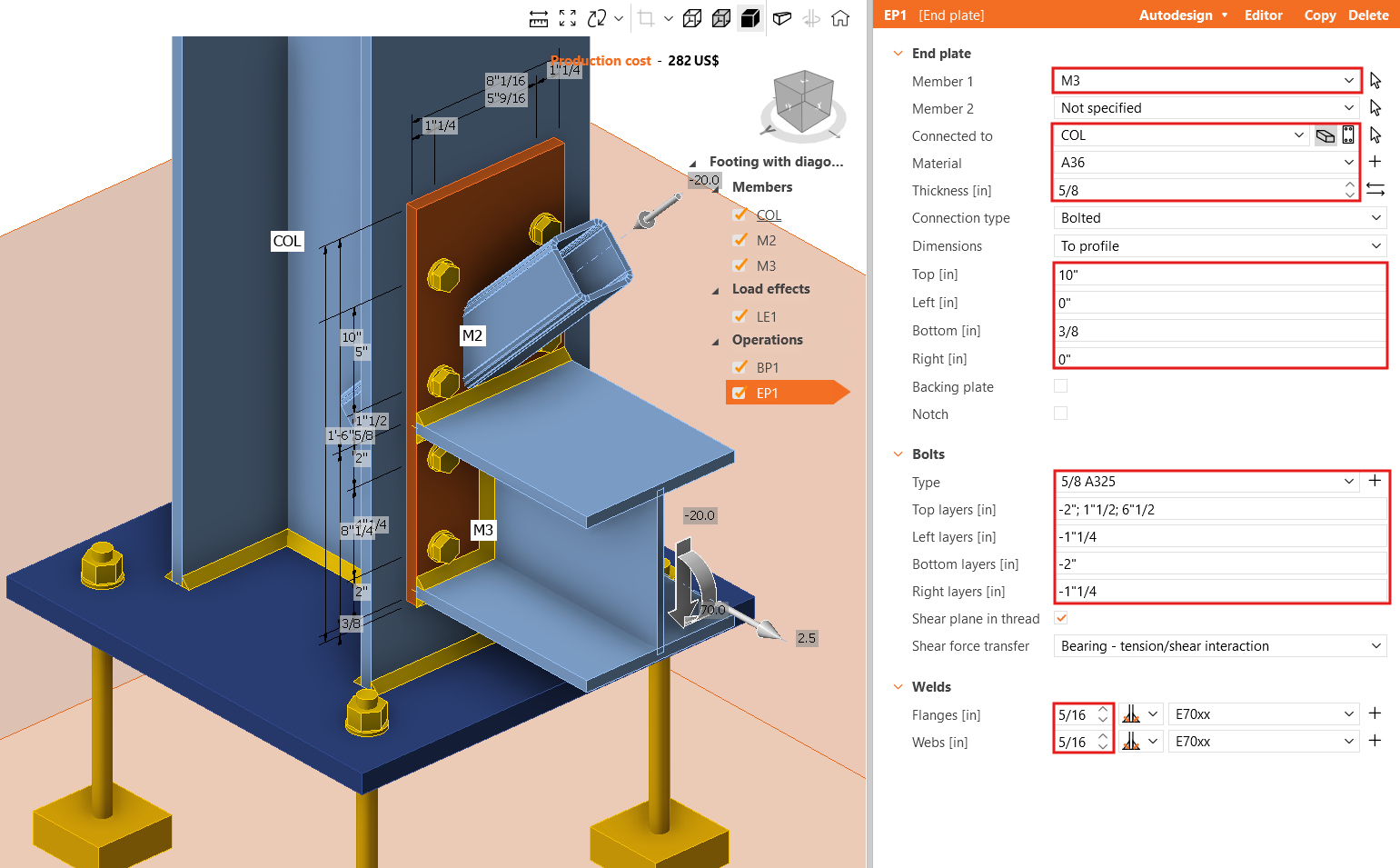
Modify the properties of the operation EP1.
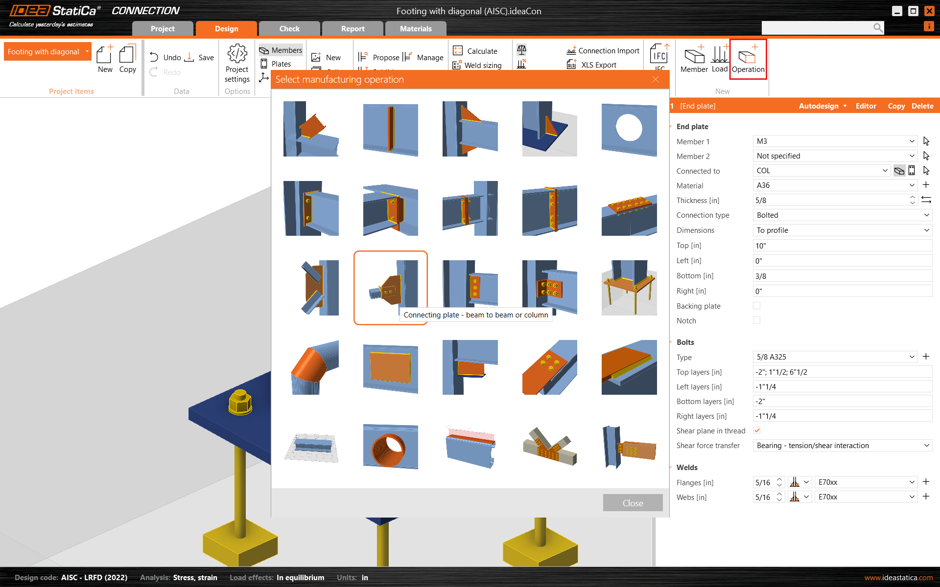
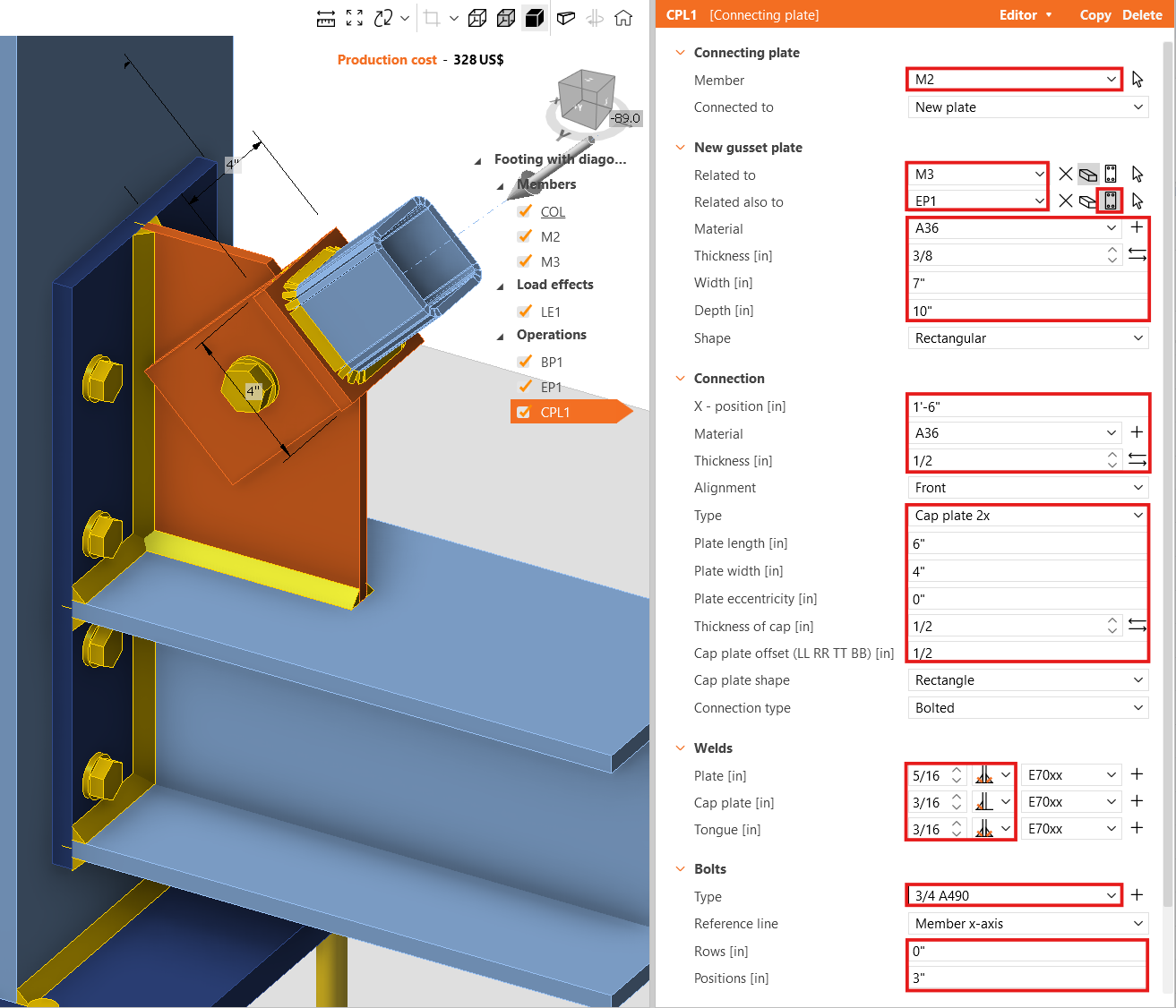
Now, add the Connecting Plate.
And redefine its properties.
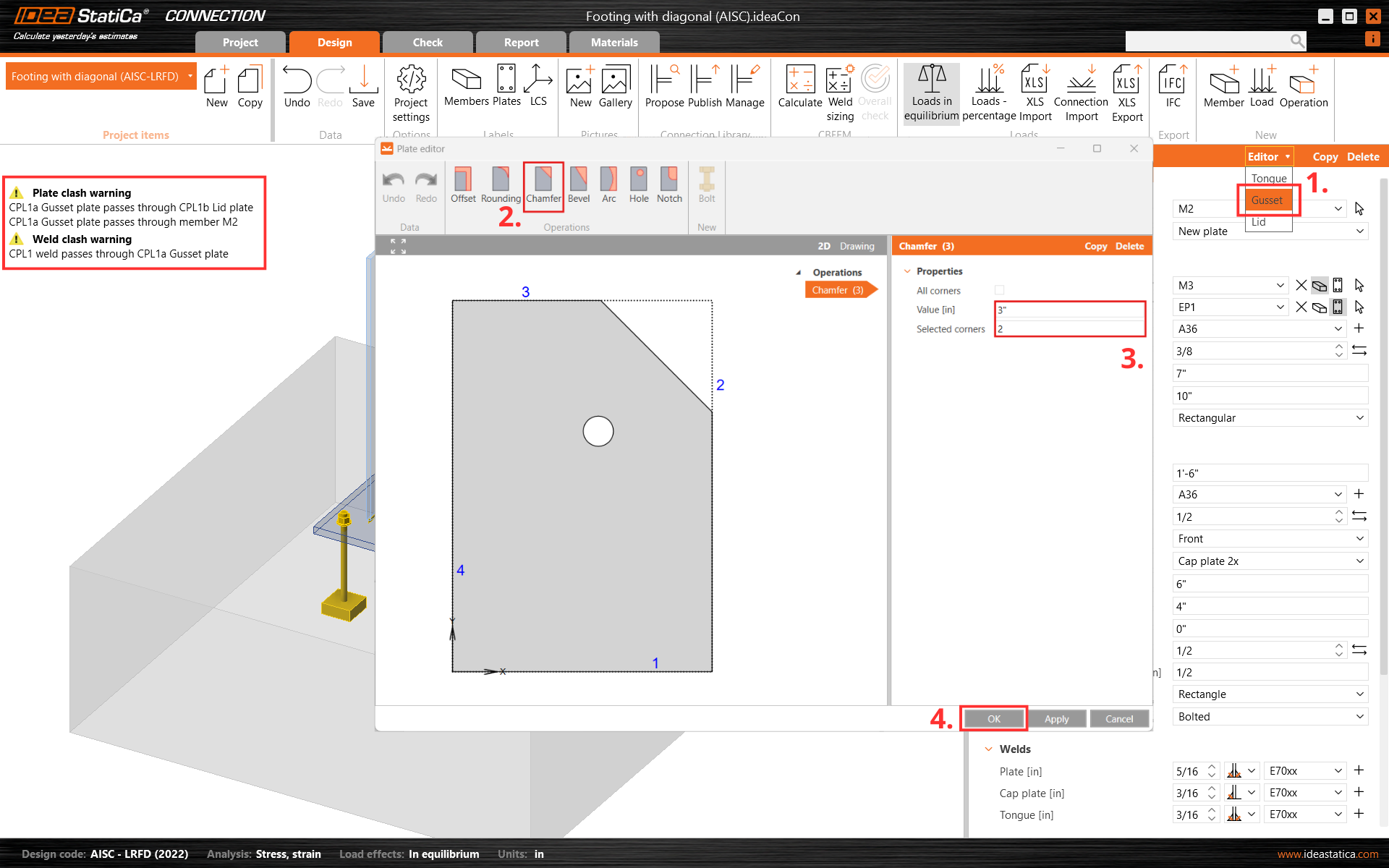
Next, cut one corner of the connecting plate CPL1. For this, go to the Editor - Gusset plate and create a Chamfer at corner number 2.
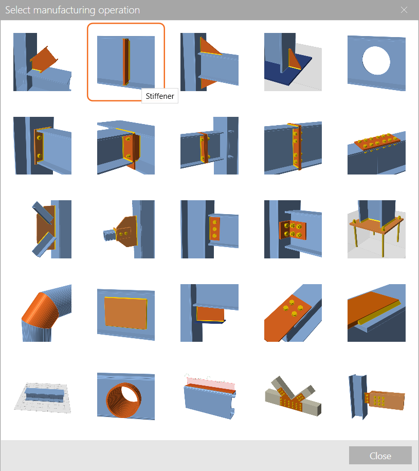
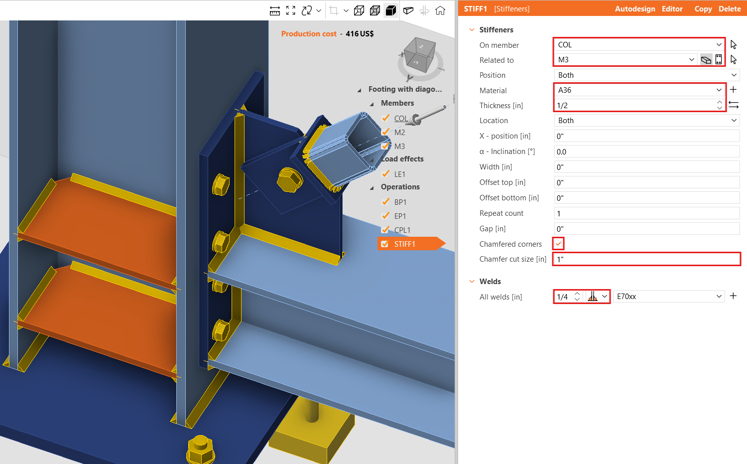
Finish the design with the operation Stiffener.
And set the correct properties of STIFF1.
Let’s check the final design of the joint.
5 Calculation and Check
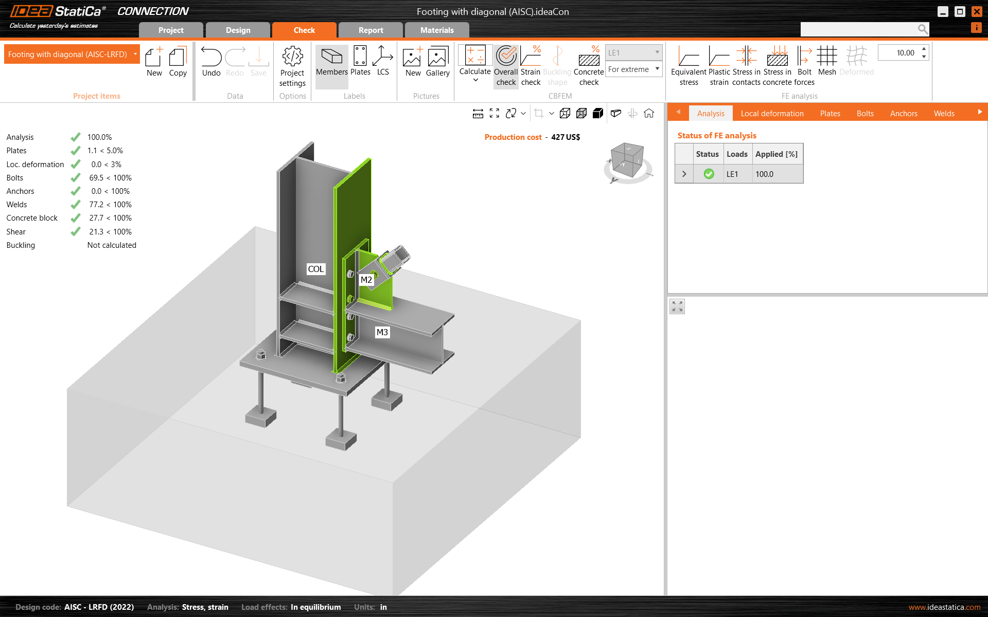
Start the analysis by clicking Calculate in the ribbon. The analysis model is automatically generated, the calculation based on CBFEM is performed, and we can see the Overall check displayed together with the fundamental values of check results.
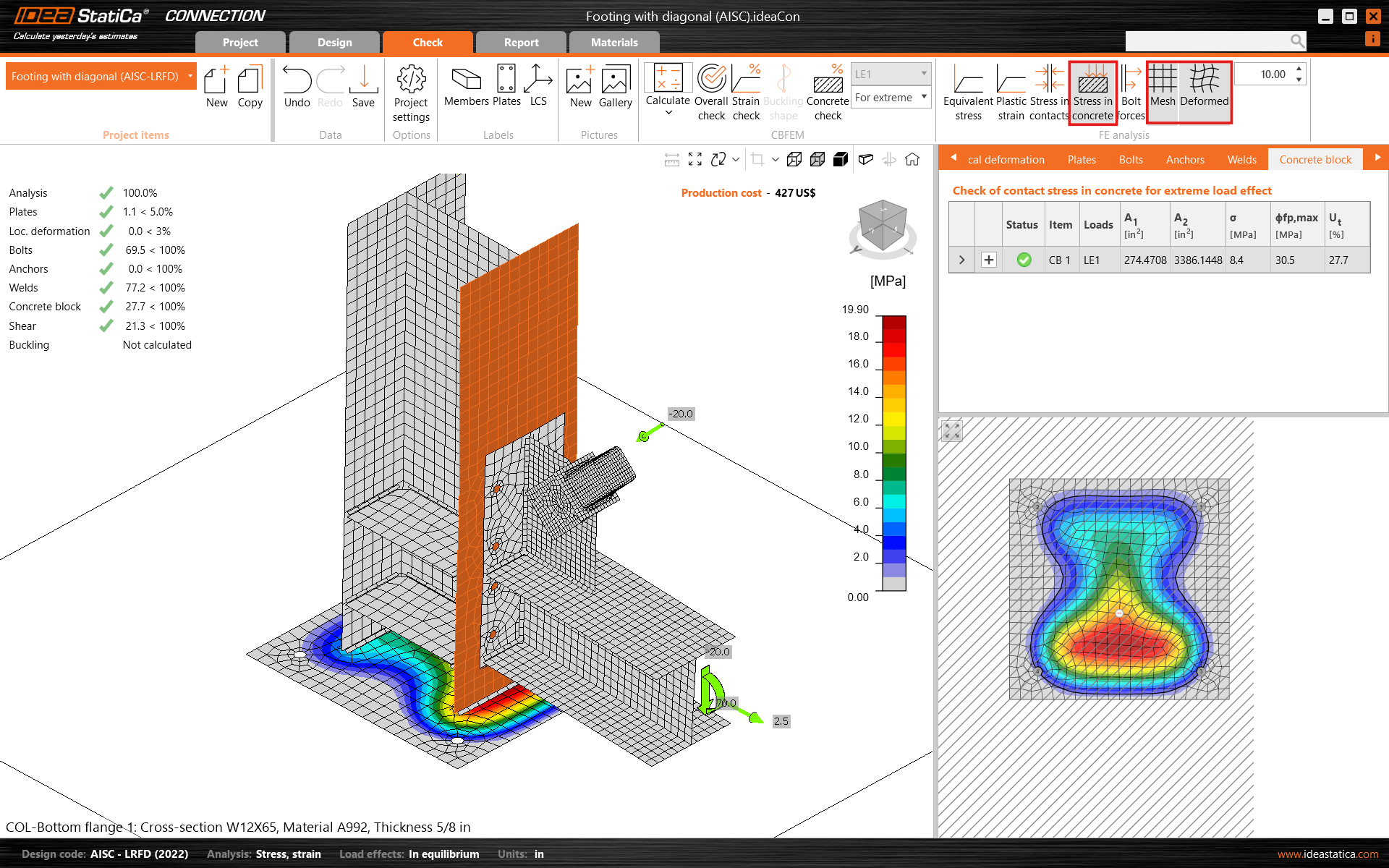
Go to the display tab Check, and activate Stress in concrete and Mesh from the ribbon to get a complete picture of what is happening in the joint. Open the tab Concrete block to see the detailed results for this item.
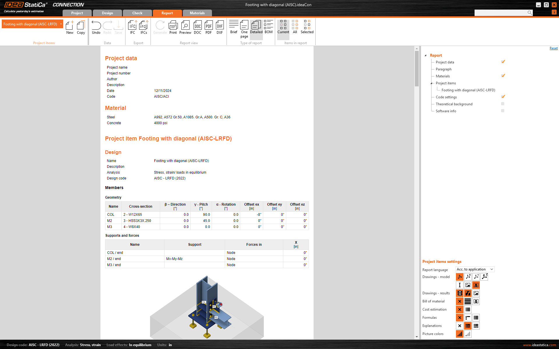
6 Report
At last, go to the tab Report. IDEA StatiCa offers a fully customizable report to print out or save in an editable format.
You have designed, optimized, and code-checked a structural steel joint according to AISC.