
Known limitations for Detail 3D
Introduction
At the beginning of this text let us define what the application is for. In the current version, we developed tools and verified the solution only for anchoring steel structures in simple concrete blocks and prismatic members. Because the 3D CSFM (3D Compatible Stress Field Method), which is a core of the IDEA StatiCa Detail application, is a general method we focus the next development on adding tools and doing more verifications supporting more use cases like pier caps, punching of slabs, bridge diaphragms, etc.
The following text is divided into two parts - limitations of the application and method itself and limitations of the import from IDEA StatiCa Connection.
Limitations of the application
Reinforced concrete
The 3D CSFM is not designed for plain concrete or lightly reinforced concrete. In this case, the result of the calculation can lead to misleading results or divergence of the non-linear calculation.
You can read more in Theoretical background.
So you need to model structures that meet the requirements of the detailing rules defined in codes especially the maximum distance of reinforcement bars. In the following figure, you can see where the method starts to be reliable. The left model does not contain any stirrup leg in the volume around anchors. The model will be calculated successfully, but the results can be misleading because the maximum distance of sturrup legs is far from fulfilled. On the other hand, the right model has this rule fulfilled and the results will be correct.
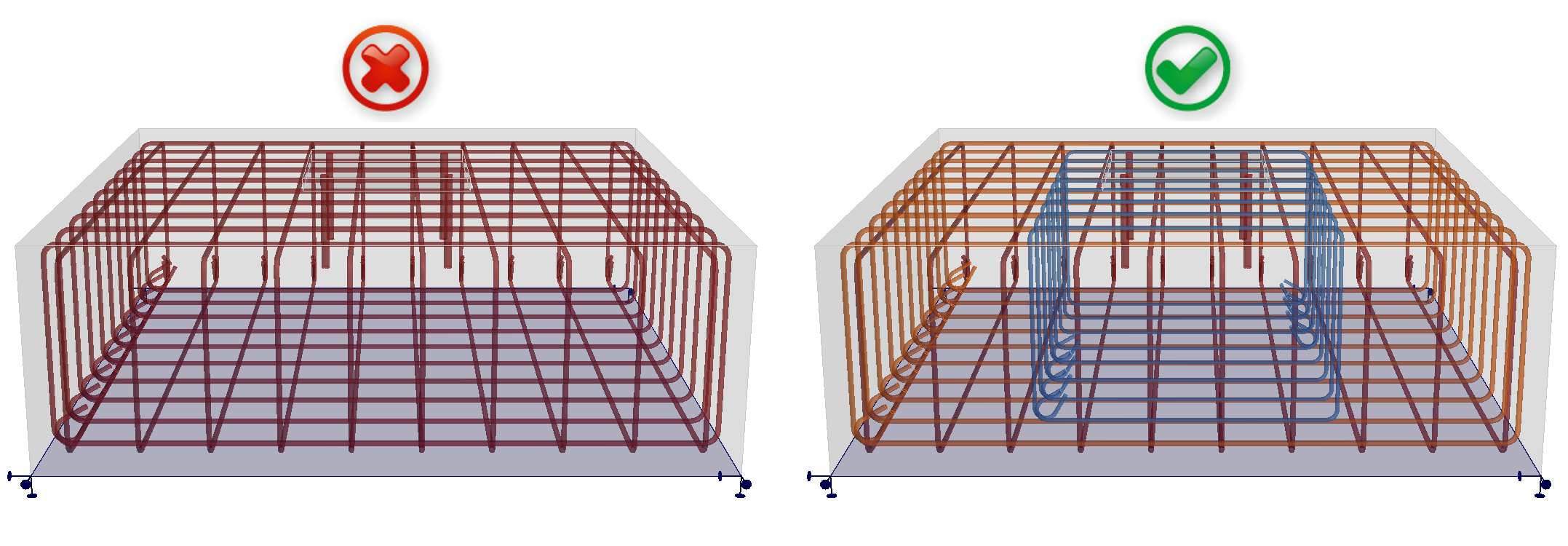
To wrap it up, follow the detailing rules defined in your code and you will obtain correct results.
Ultimate Limit State
All the calculations and code checks are implemented for ULS only. The definition of materials and the way of calculation itself must be different for SLS. You can see this difference in the Detail 2D.
Anchor check
The element of the anchor is defined as being able to transfer normal tensile or compression forces as well as shear forces also considering the bending stiffness as described in the Theoretical background. However, it is not possible to do the shear check (EN 1992-4 - 7.2.2.3.1) and interaction of tensile and shear check (EN 1992-4 - 7.2.2.4) in the Detail application.
This code-check is implemented in the IDEA StatiCa Connection application. Users can model the anchoring there, check anchors, and use the option to export the model to the Detail application.
To conclude, the shear load can be transferred from anchors to concrete block, but the code check itself cannot be done.
Contact stress from Shear
It is possible to transfer shear load from anchors or shear lugs to the concrete volume (and then, of course, to reinforcement, etc.). The contact stress between the concrete and the anchor or shear lug is not checked and is only informative.
Overturning
If the load input causes overturning of the model, the model will calculate until the divergence or reaching of a criterion. This usually takes a long time and you receive the following result:
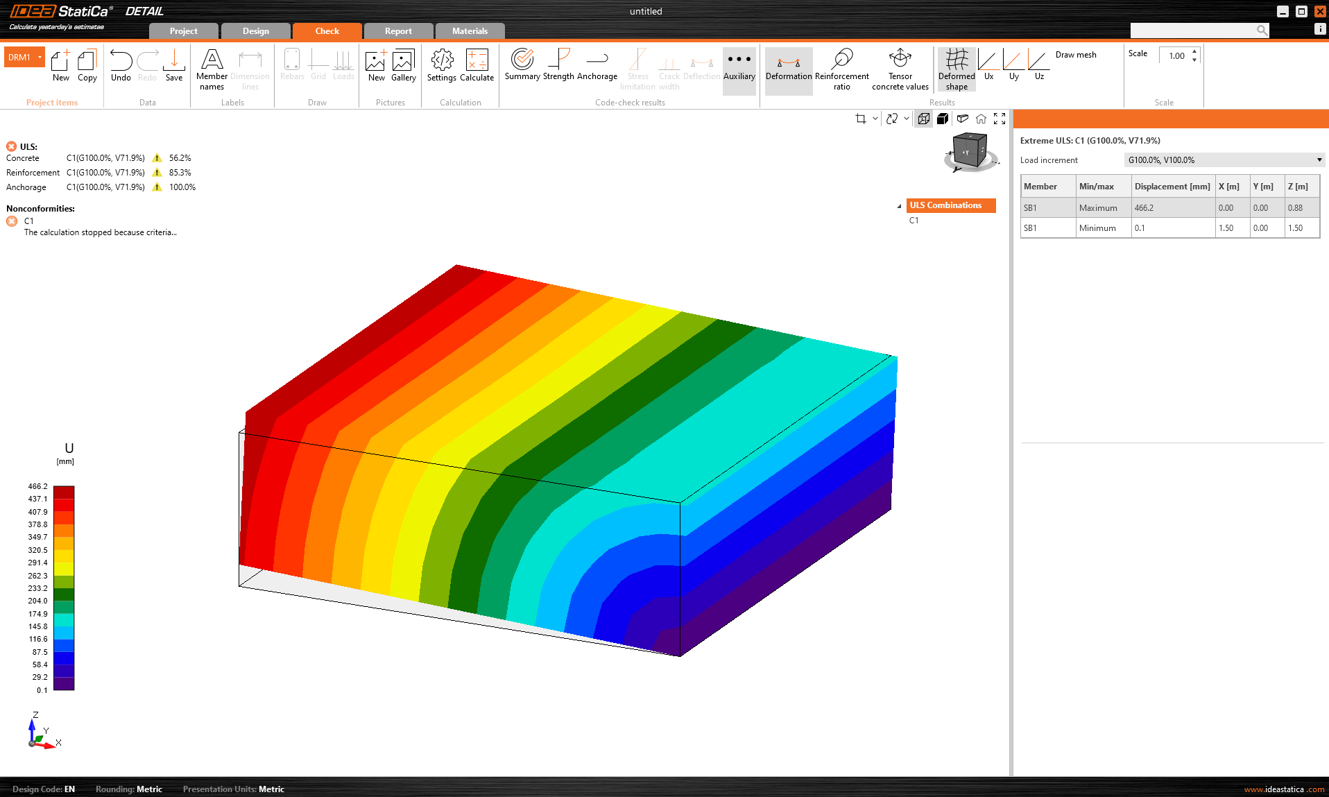
The percentage of the transferred load is displayed. Moreover in Auxiliary results extreme deformation is shown.
Workaround: It is recommended to calculate any model first with the Multiplier of default mesh size set to a high value (4-5). This multiplier can be found in Settings -> Mesh settings. The calculation will be quick and you will be able to see if the overturning is the problem or not.
Limitations of import form Connection
Stand-off
Only Direct contact can be imported to Detail. For the Mortar joint, the thickness of the mortar joint is neglected. If the thickness is reasonable, the results are only slightly influenced.
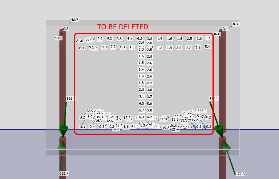
Workaround: For the option of Gap, it is assumed that the load is transferred completely by anchors. Users can import geometry, neglect the base plate, and leave only the loaded anchors in the model. In this case, the group of forces acting on the base plate must be manually deleted.
Contacts
Generally, the import of forces acting on the base plate by contact is not supported. This applies to both the edge-surface contact and the surface-surface contacts.
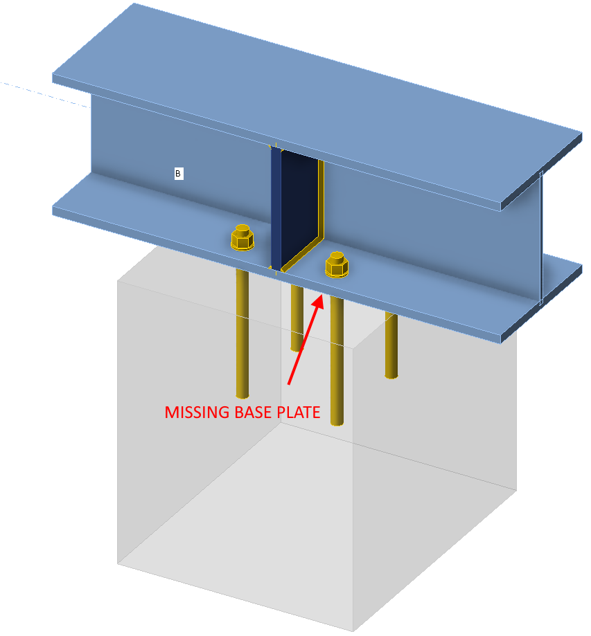
Anchoring by member
Only models anchored via the base plate can be correctly imported to the Detail application. For models, where members are connected to concrete blocks directly, the connecting plate of the member with anchors is imported without loads.
Imported loads and user-input loads combination
Imported loads and user-input loads cannot be combined within one model. Because of the reasons described in the Theoretical background. Anchors are imported disconnected from the base plates. If you create a user-defined load case, it is obvious that the load will not be transferred correctly.
Workaround: Copy the imported Project item, delete all imported loads, interconnect all anchors with the base plate, and then you can input your user-defined load case.
One concrete block
Only one concrete block is supported in Detail. It applies also to the import from the Connection.
Default material
The Connection application by default does not contain materials for reinforcement like B500B. If you intend to import cast-in reinforcement, you will need to manually switch material in the Detail application.