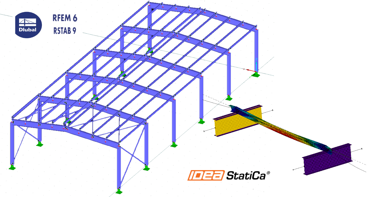
RFEM/RSTAB BIM link for steel member design (EN)
How to activate the link
- Download and install the latest version of IDEA StatiCa
- Make sure that you are using a supported version of your FEA/BIM solution
IDEA StatiCa integrates BIM links into your FEA/BIM solutions during its installation. You can check the status and activate more BIM links for software installed after in the BIM link installer.
Please note that some FEA solutions require additional steps to fully activate their BIM link to IDEA StatiCa.
Open IDEA StatiCa and navigate to the BIM tab and open the BIM link installer (Activate your BIM link...).
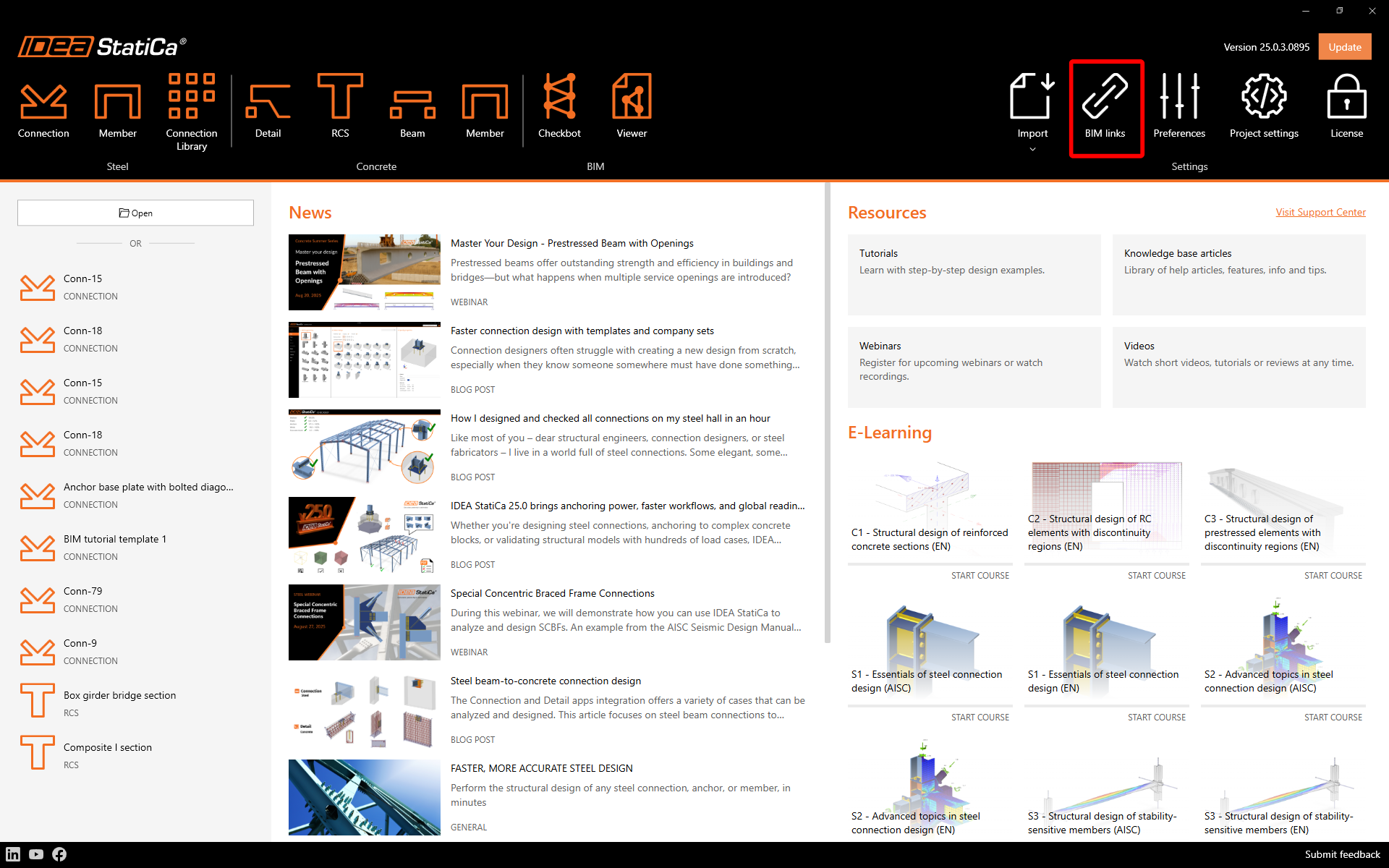
A notification "Do you want to allow this app to make changes to your device?" may appear, if so, please confirm with the Yes button.
How to activate the link - RFEM 5 and RSTAB 8
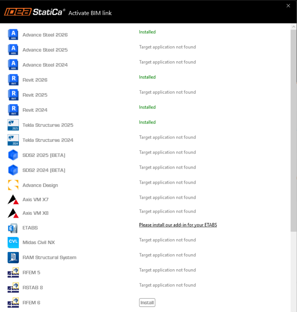
The BIM link for the selected software (if found) is installed. The screen also tells you the status of other BIM links that may have already been installed. Possibly click Install to activate any BIM link.
How to activate the link - RFEM 6 and RSTAB 9
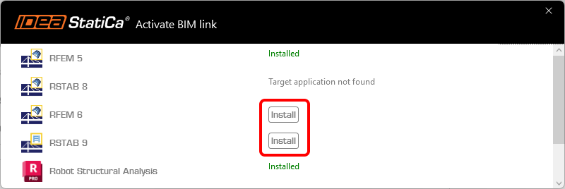
In the BIM link installer, click Install to create a shortcut icon IDEA StatiCa 2X.X for RFEM 6/IDEA StatiCa 2X.X for RSTAB 9 on your desktop.
Note: original file in path C:\Program Files\IDEA StatiCa\StatiCa 2X.X\net6.0-windows\IdeaRFEMLink.exe or IdeaRSTABLink.exe
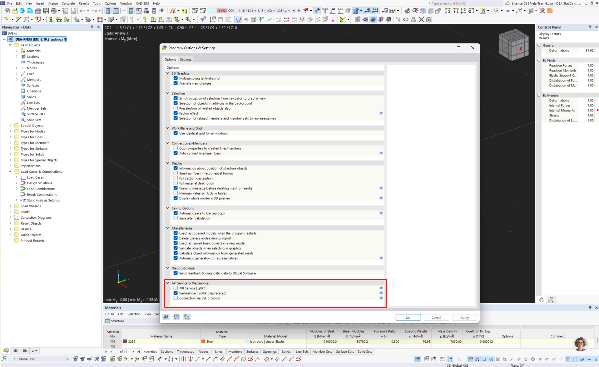
Open RFEM 6/RSTAB 9 and navigate to the menu Options and Program options, and turn on the WebService to enable the data transfer.

How to use the link
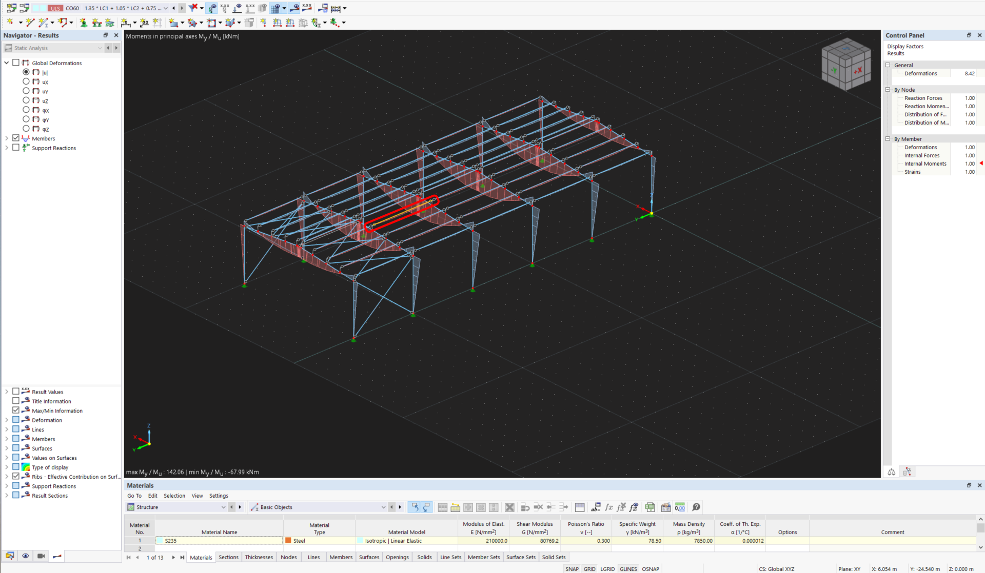
Download and open the attached project, and run the calculation to get the internal forces over the structure.
How to use the link - RFEM 5 and RSTAB 8
In the ribbon menu navigate to Add-on modules and External Modules and IDEA StatiCa Checkbot.
How to use the link - RFEM 6 and RSTAB 9
In RFEM 6/RSTAB 9 there is no ribbon menu command. Instead, with opened RFEM 6/RSTAB 9 project, go to your desktop and run the shortcut icon IDEA StatiCa 2X.X for RFEM 6/IDEA StatiCa 2X.X for RSTAB 9.

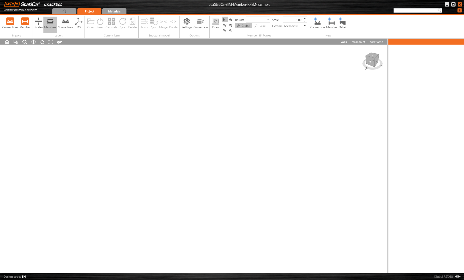
The Checkbot app, which serves as the BIM link manager opens, and you can start a new project.
Select the New option with project type Steel and design code EN. Then select Create project.
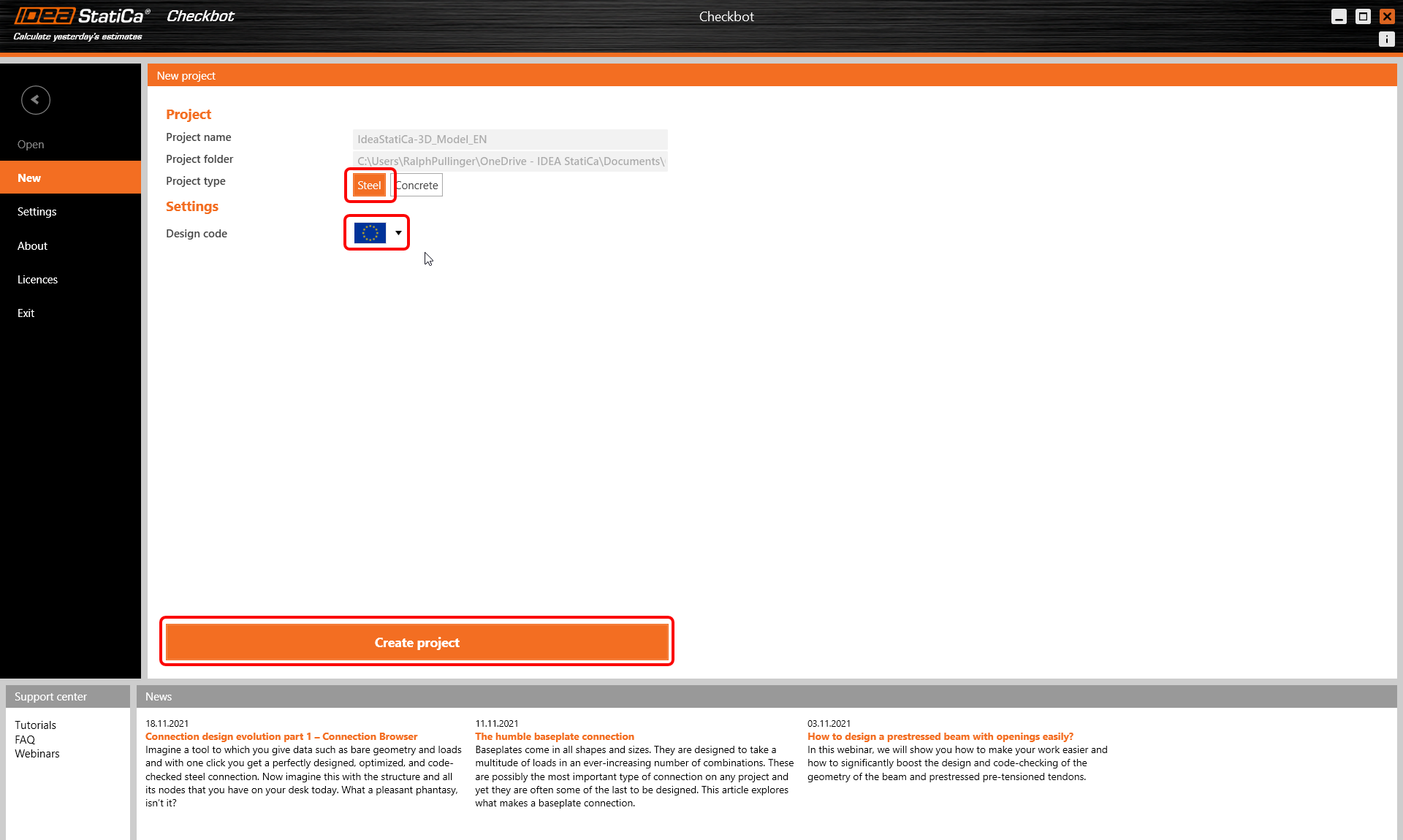
The new Checkbot project is ready to import connections from RFEM/RSTAB.
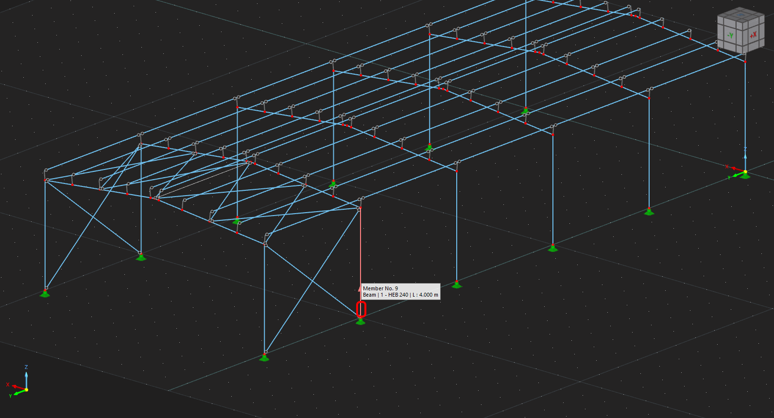
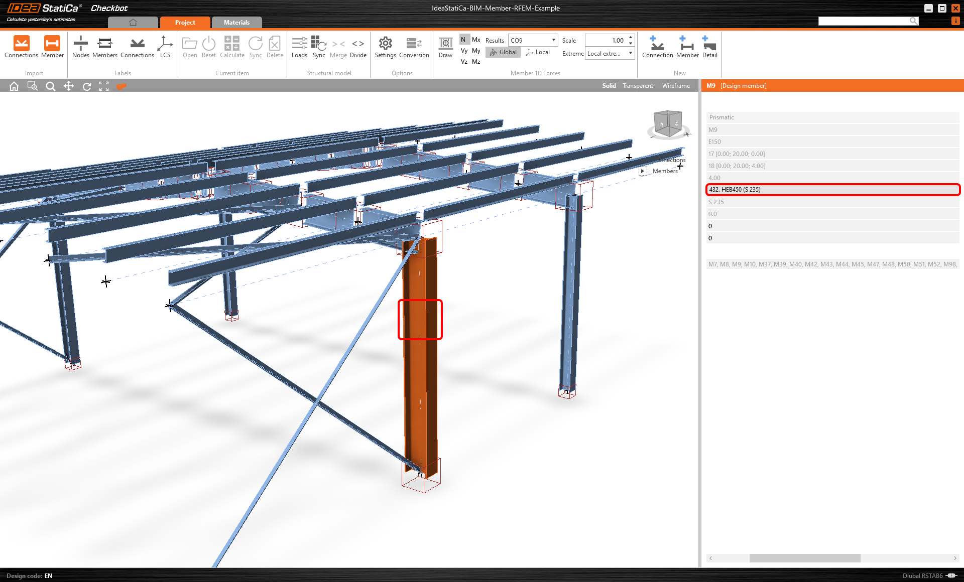
In RFEM/RSTAB, select one of the inside members, as shown in the following picture.
Import
Then, in Checkbot select the Member command.
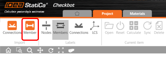
This will import the member with load effects and all related members into Checkbot - with the exact coordinates, orientations, and section sizes as per the FEA/BIM model.
Please note that your node and member numbering might be different.
Geometry
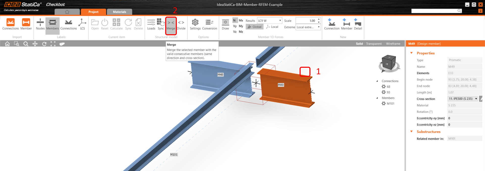
In Checkbot you can merge separated members into a continuous one. Merge both supporting beams as related members. Select the related member M-49, click the Merge command.
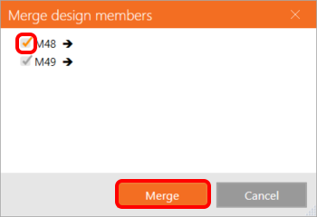
Here, select also the the M-48 related member.
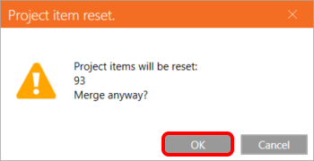
And confirm the reset of the affected project item - connection 93.
Repeat the same for the other supporting related members.

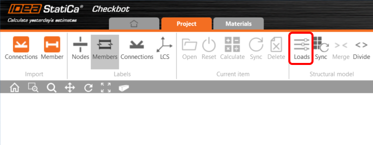
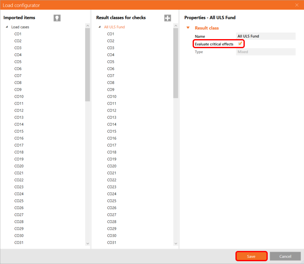
You can control which load cases and combinations will be used for the analysis in the Checkbot application by clicking on Loads and managing the Result classes for checks column.
Note: By default, the Evaluate critical results function is enabled, which filters out the non-dangerous load cases and combinations to speed up the calculation. You can turn it off, and all combinations will be included in the calculation. You can delete or add items via right-click or drag and drop between the columns.
Design
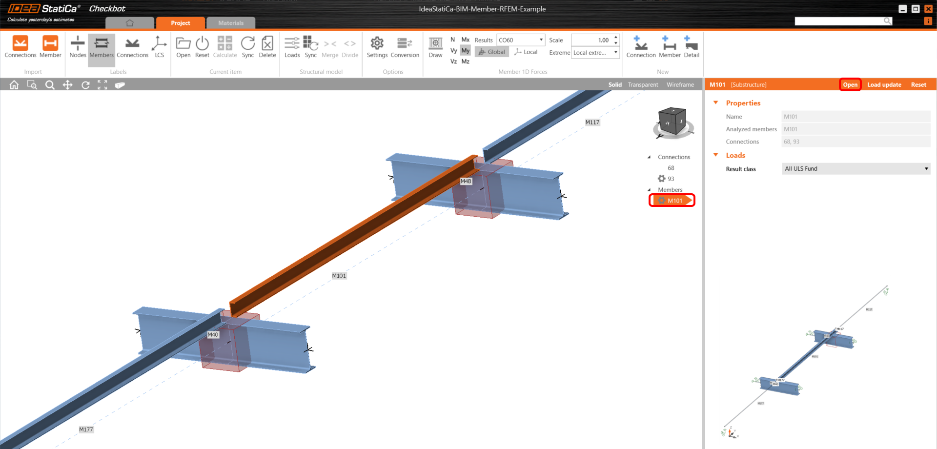
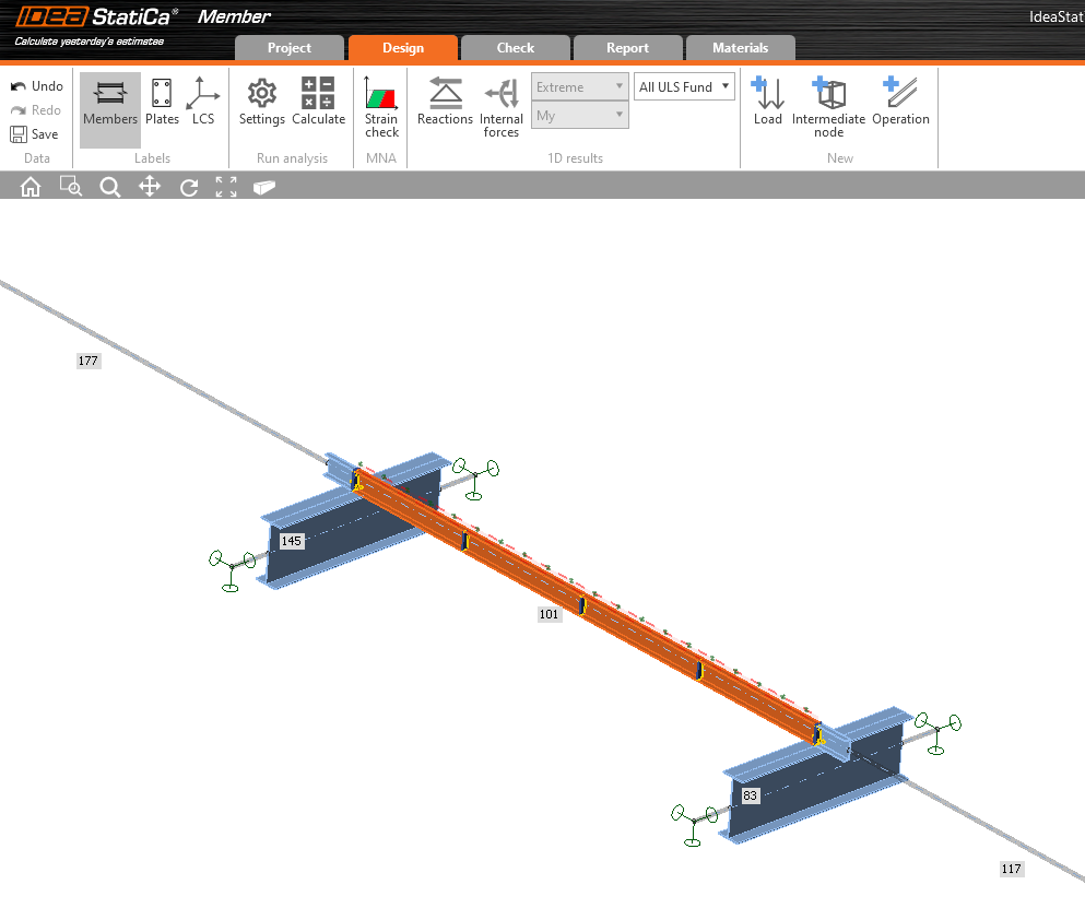
Now, select member M101 and click Open to start the design.
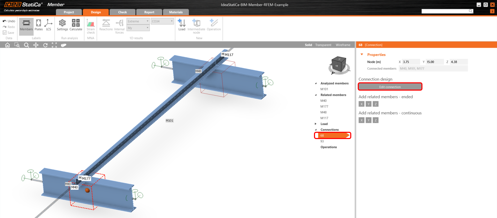
First, design connection 68. Select it, and click Edit connection to open the application Connection.
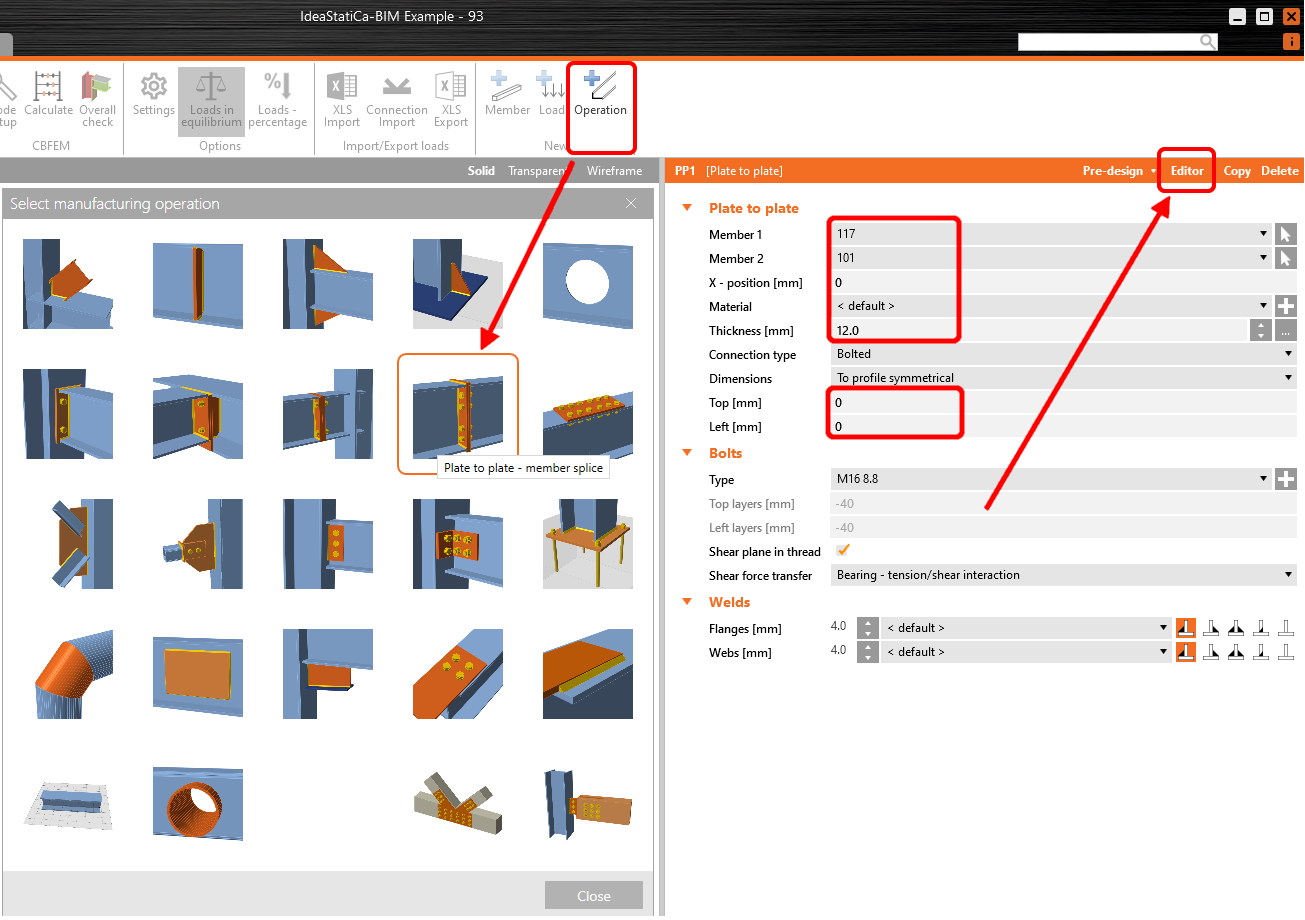
Click on Operation and select Plate to plate. Set the values according to the picture. Then click on Editor.
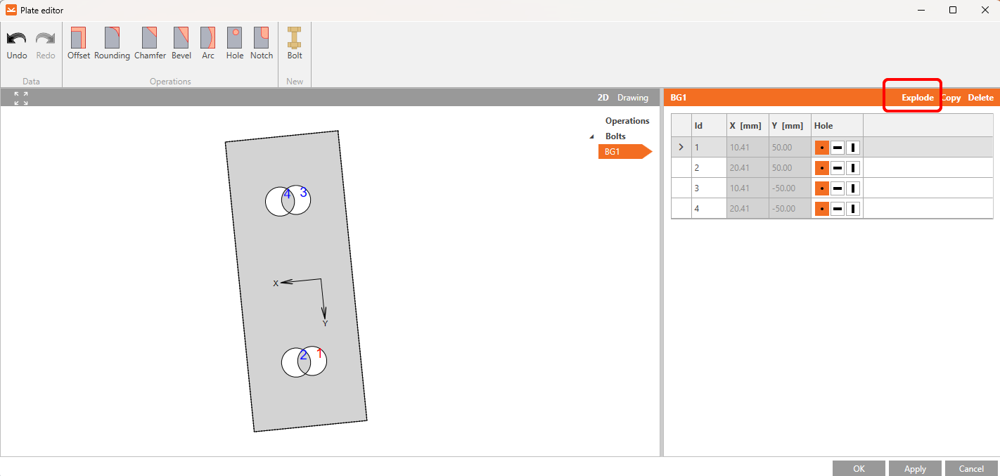
Click on Explode and delete bolts 1 and 3.
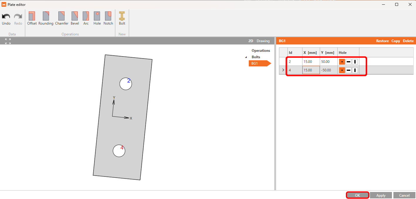
And set coordinates for bolts 2 and 4 according to the picture. Confirm changes by clicking OK.
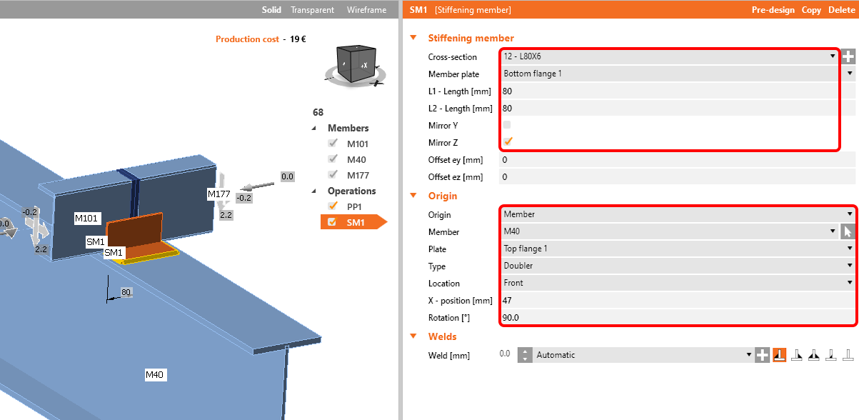
The next operation is the Stiffening member, set L-profile L80x6 with the following values.
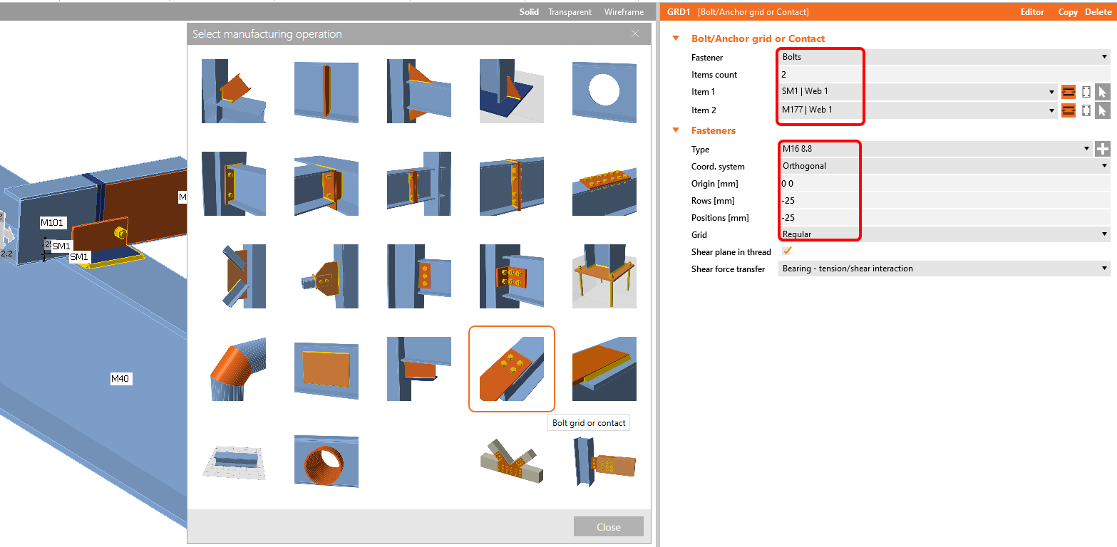
Add the operation Bolt/Anchor grid and modify the parameters.
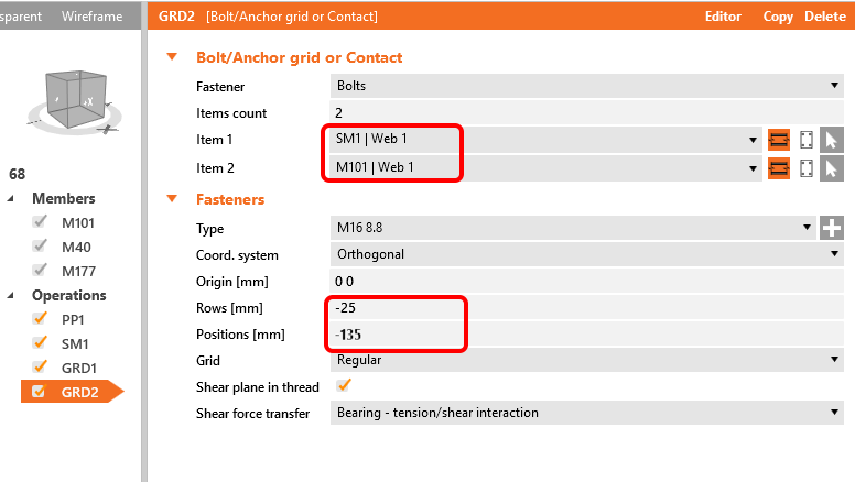
Copy this operation and change the selected values.
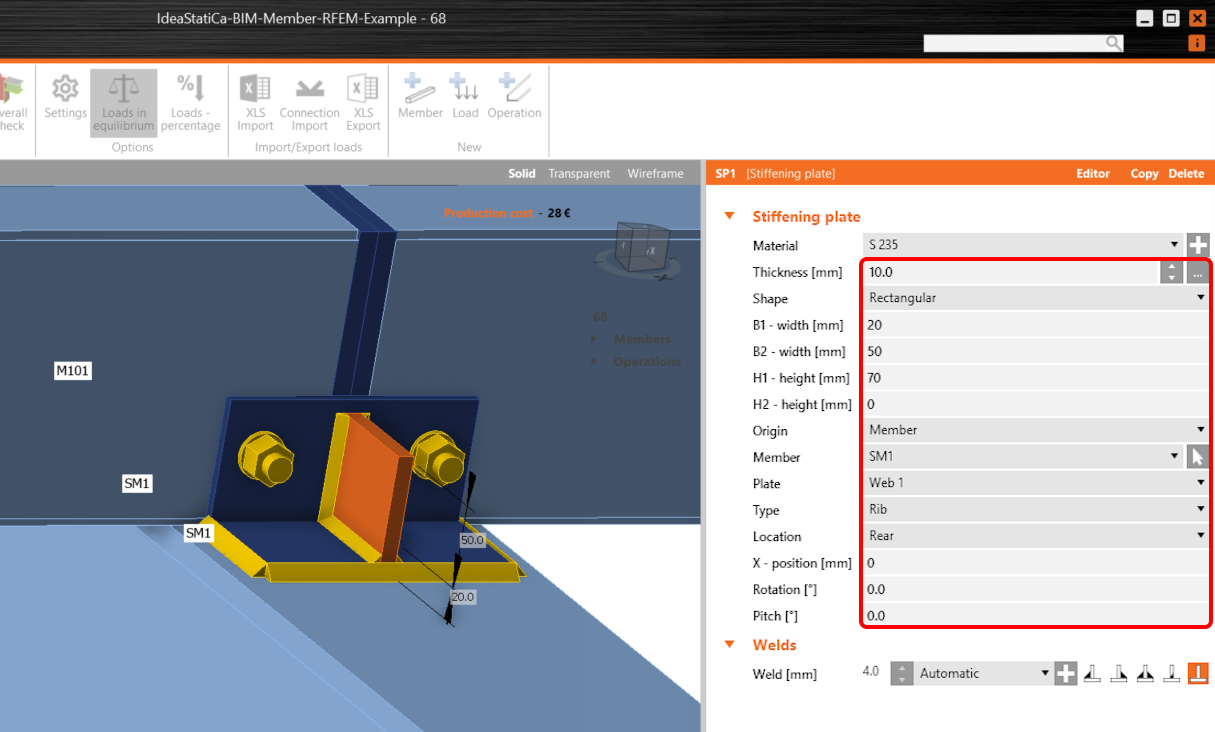
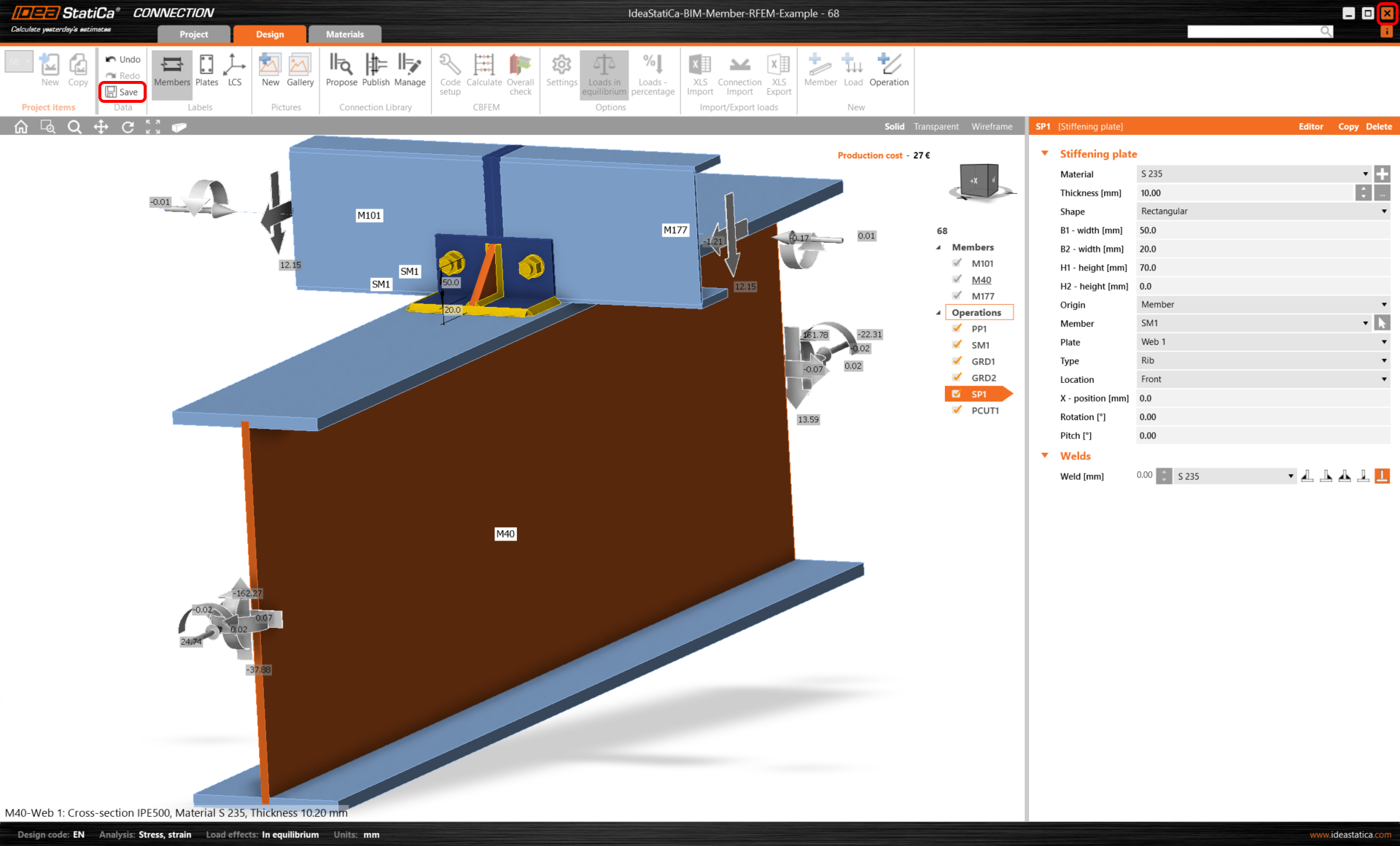
Now add a Stiffening plate to the joint.
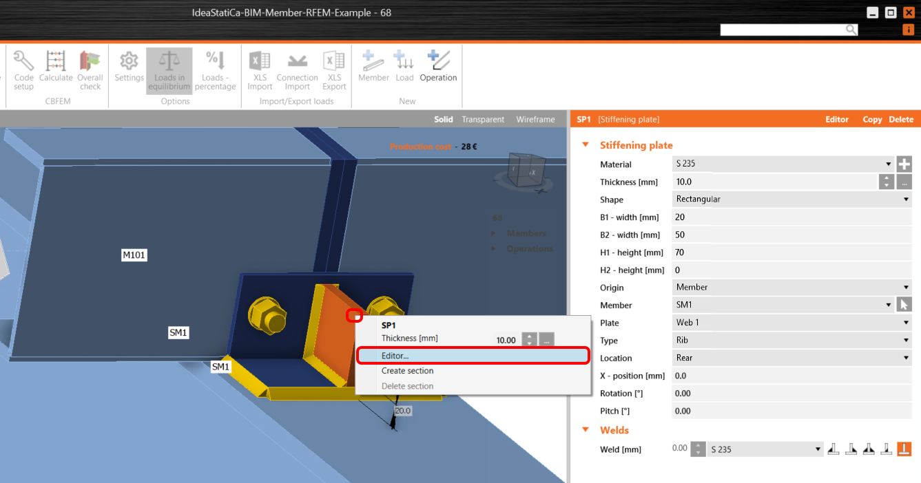
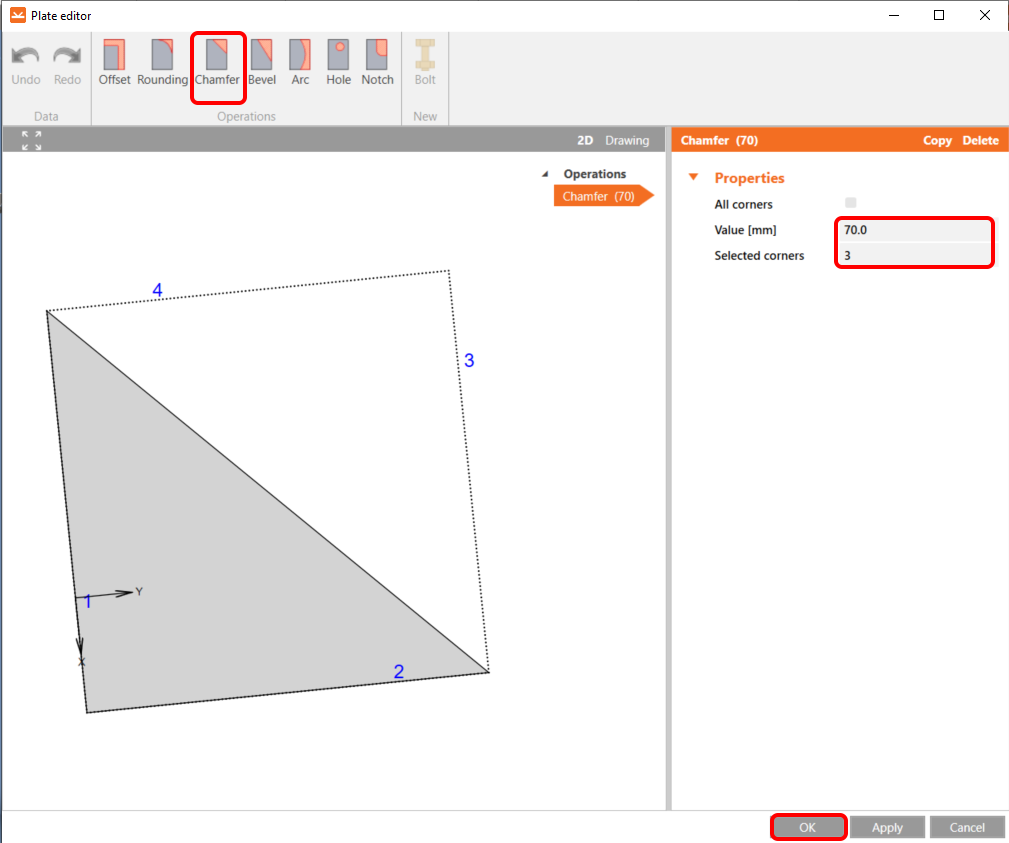
And modify its shape in the plate Editor.
Here, add the Chamfer operation to cut the plate.
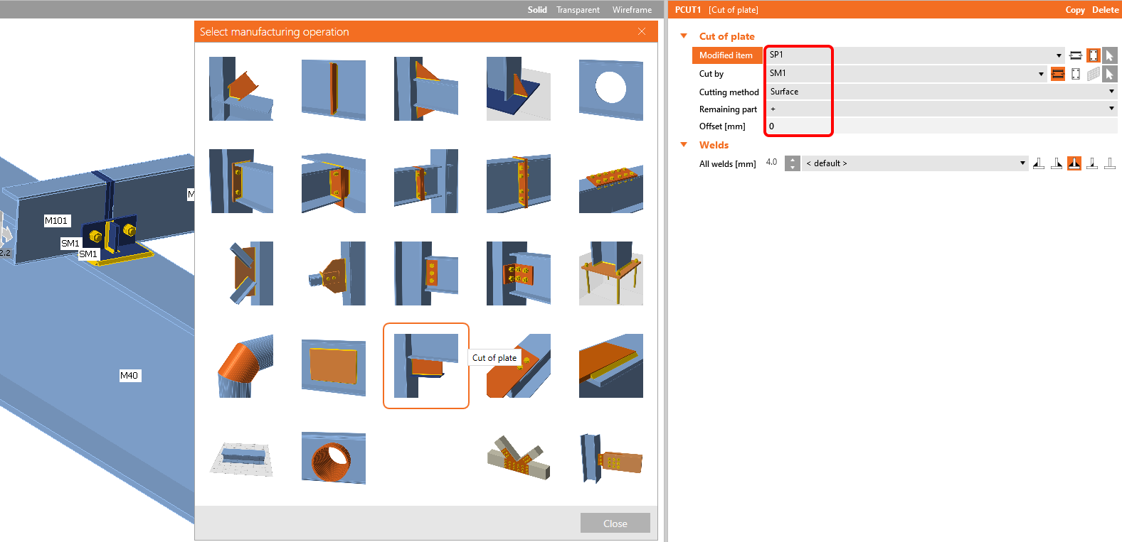
The last operation is the Cut of plate.
Now click on Save and close the module Connection.
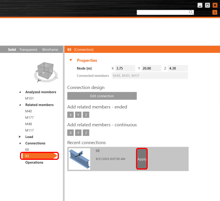
As we have a similar connection in both nodes, you can copy the finished design to node 93 by clicking Apply.
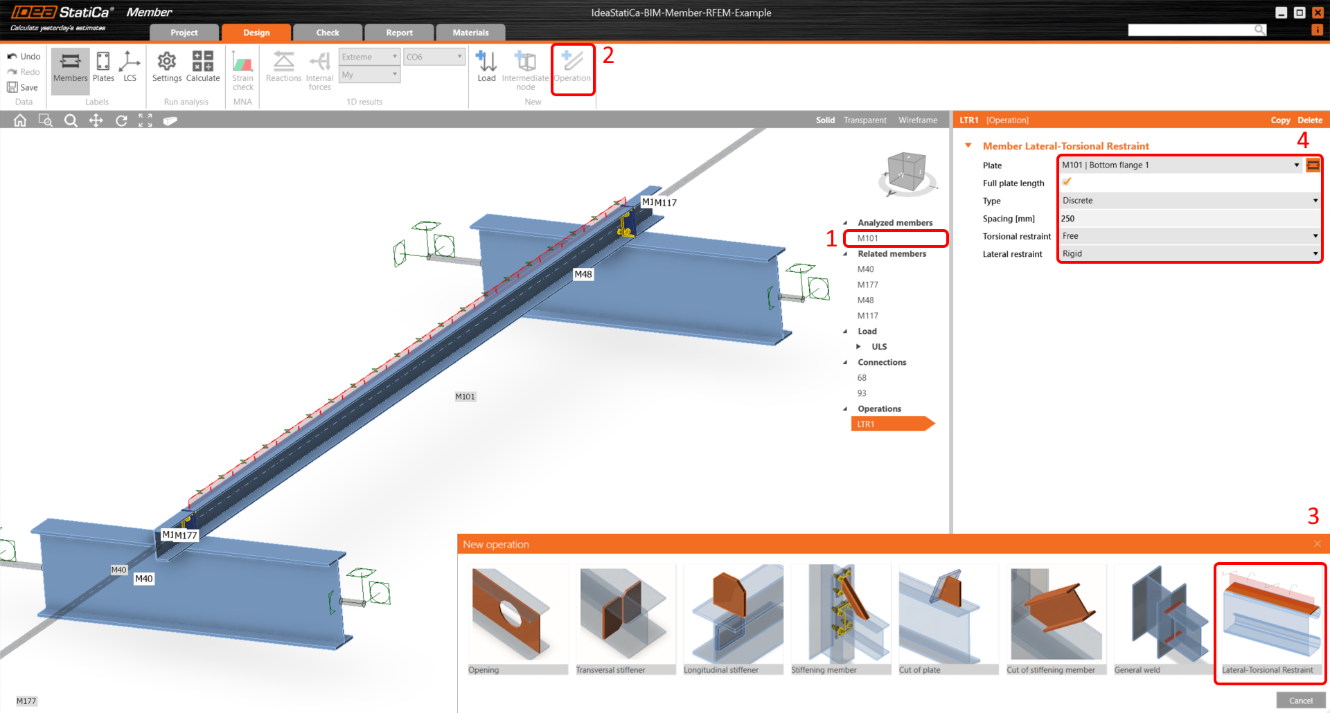
Because there are roof panels stabilizing the analyzed purlin, add the operation Lateral-Torsional Restraint to simulate it and set the parameters.
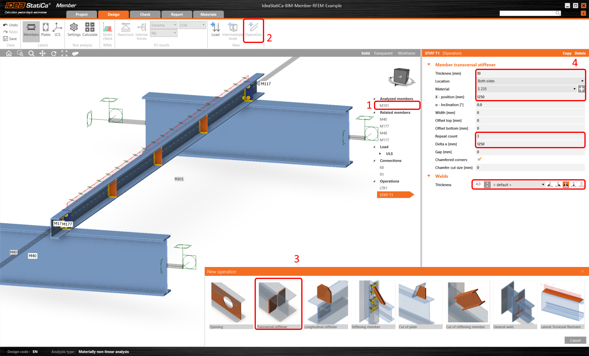
Then add the operation Transversal stiffener.
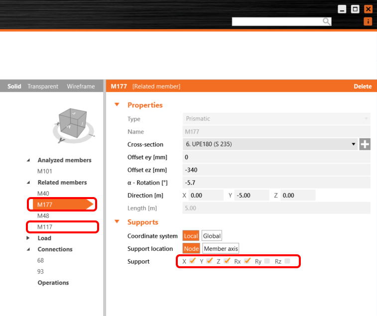
For the proper structural behavior of related members, set the supports of the connecting purlins M177 and M117 to X, Y, Z, and Rx.
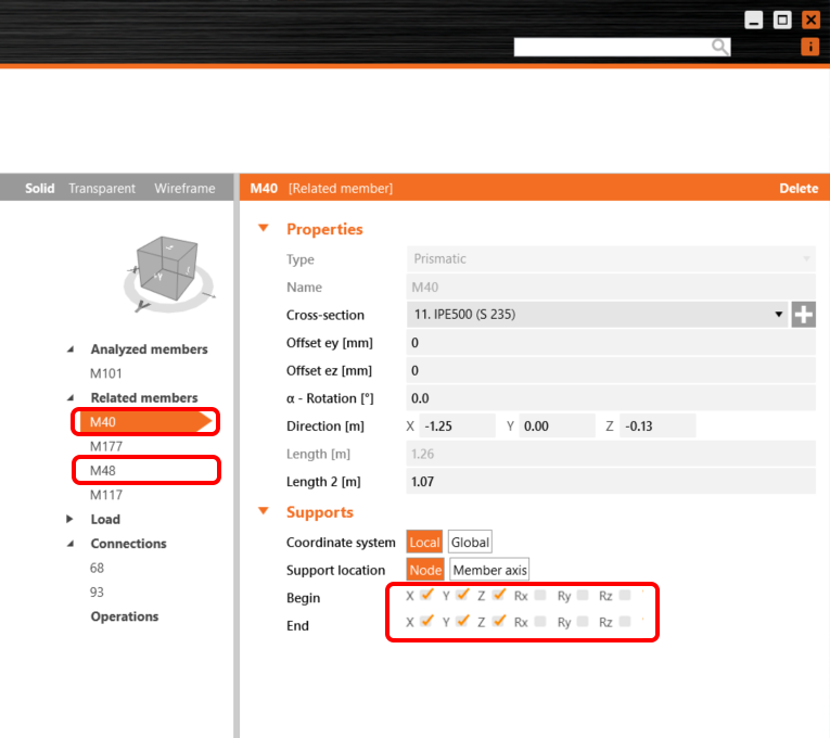
As well as for the supporting members M40 and M48 set supports to X, Y, Z.
Code-check
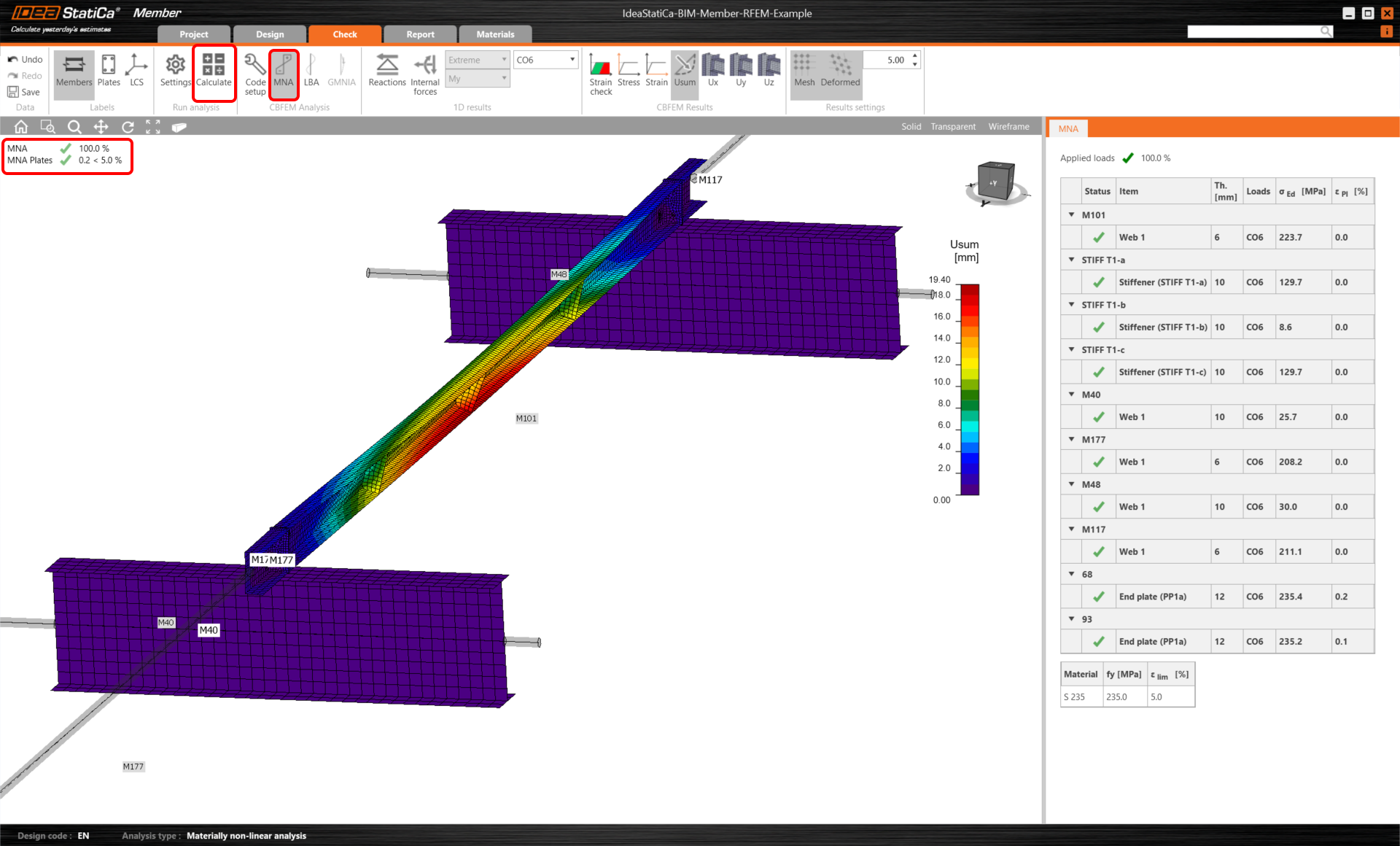
Now, the member model is ready for the analysis.
Select the Tab Check and run the MNA (materially non-linear) analysis with the Calculate button.
The second analysis is LBA (lateral buckling analysis), where we get a critical factor of less than 15. This result shows the necessity of running the GMNIA (geometrically and materially non-linear analysis).
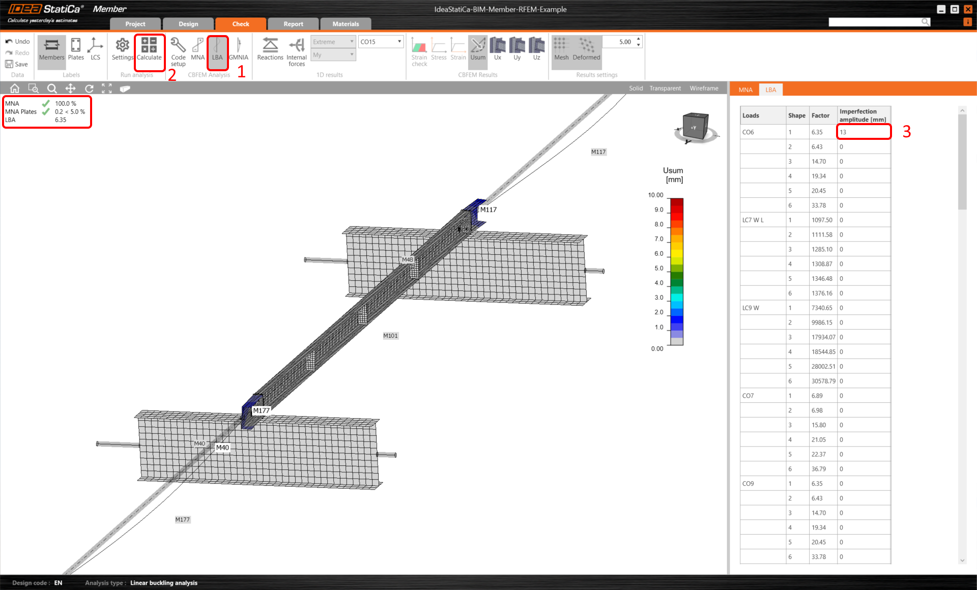
Before running the GMNIA (geometrically and materially non-linear) analysis, fill in the Imperfection amplitude value. Because lateral-torsional buckling is investigated here, factor k0 = 0.5 may be used. Amplitude 0.5x5000/200 = 12,5 mm can be applied to the first buckling mode.
Read more about:
- How to input imperfections in Member
- Member stability in IDEA StatiCa Member.
- Lateral torsional buckling
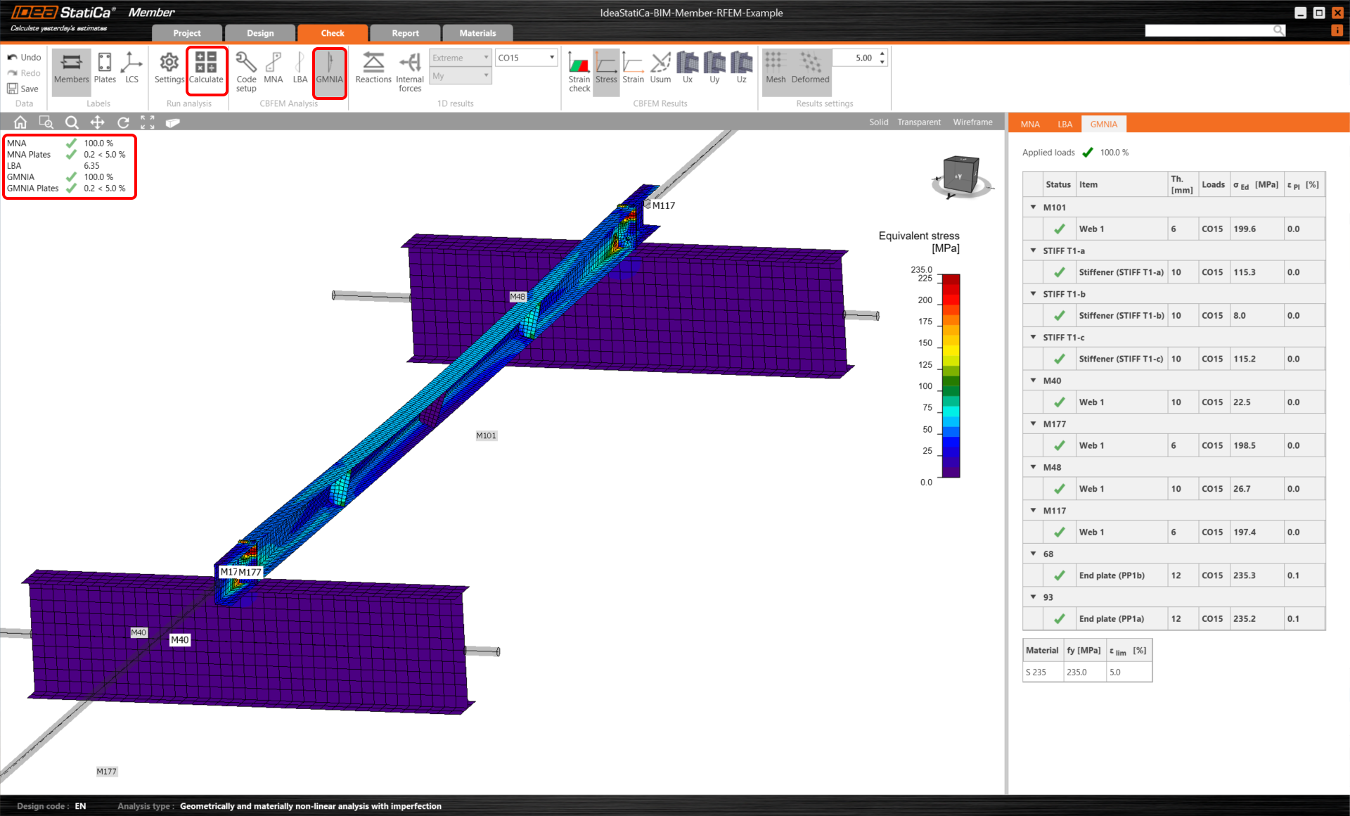
Once the analysis is finished, you can read the final code-checks, including the imperfections.
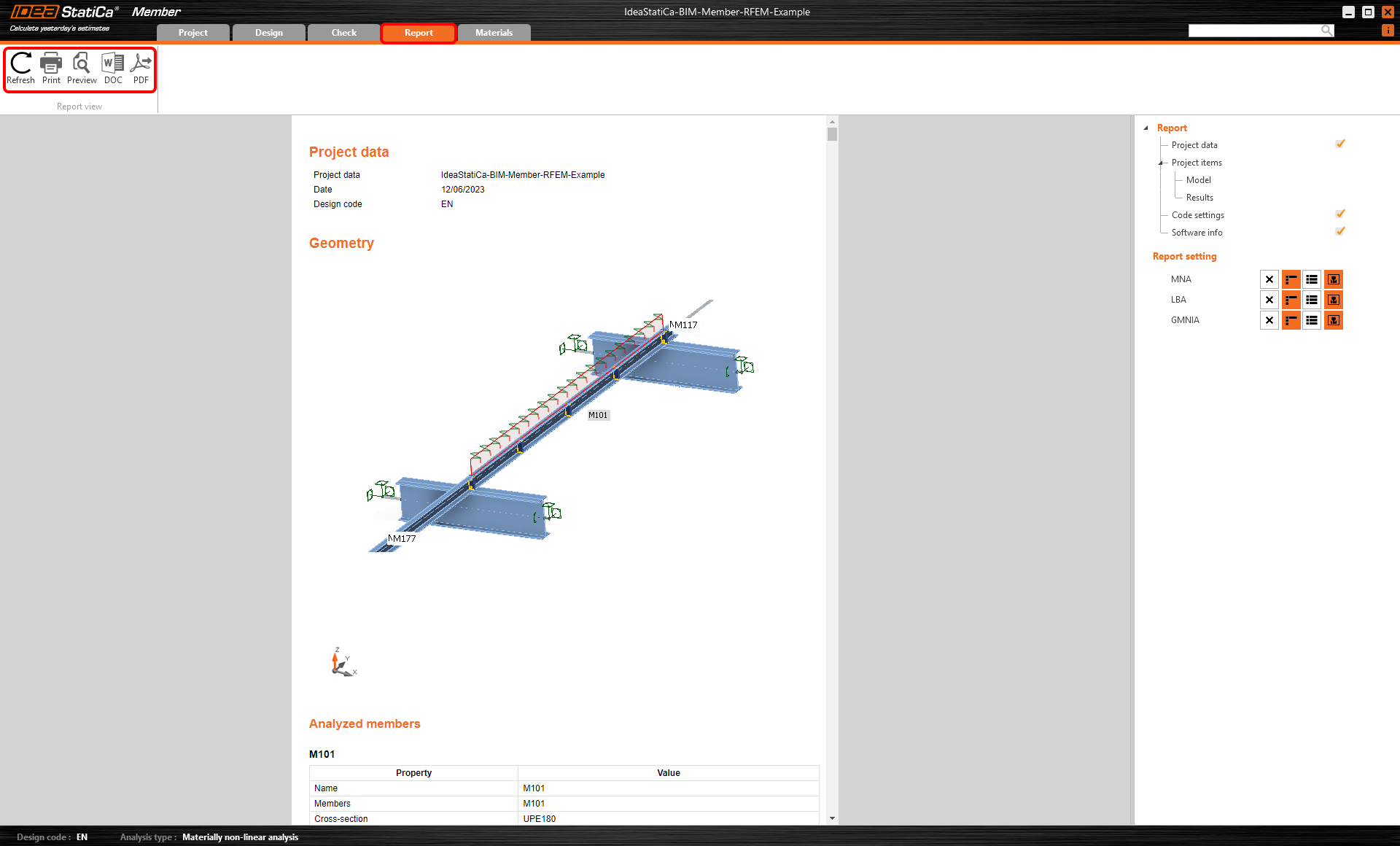
Report
At last, go to the tab Report. IDEA StatiCa offers a fully customizable report to be printed out or saved in .doc editable format.
Synchronize members
Sometimes, there are changes to your FEA/BIM model, such as different member section size or loads. These can be synchronized between Checkbot and the FEA/BIM model.
There are two possible alternatives:
- Synchronize the Current item (if one or more joints are selected)
- Synchronize the whole imported Structural model
To test this feature, you can change a member section size or shape in your FEA/BIM application or amend a load case or combination etc: change columns to a bigger section. Remember to re-analyze the FEA model.
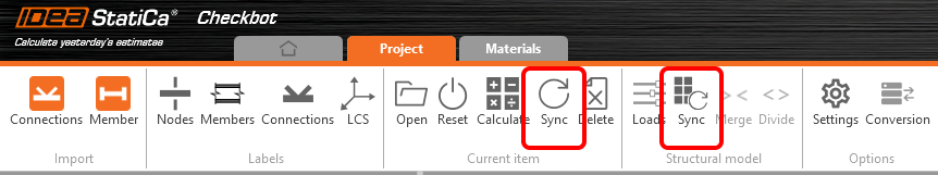
In Checkbot select the changed members (there may be more than one) and from the Current item panel, select Sync.
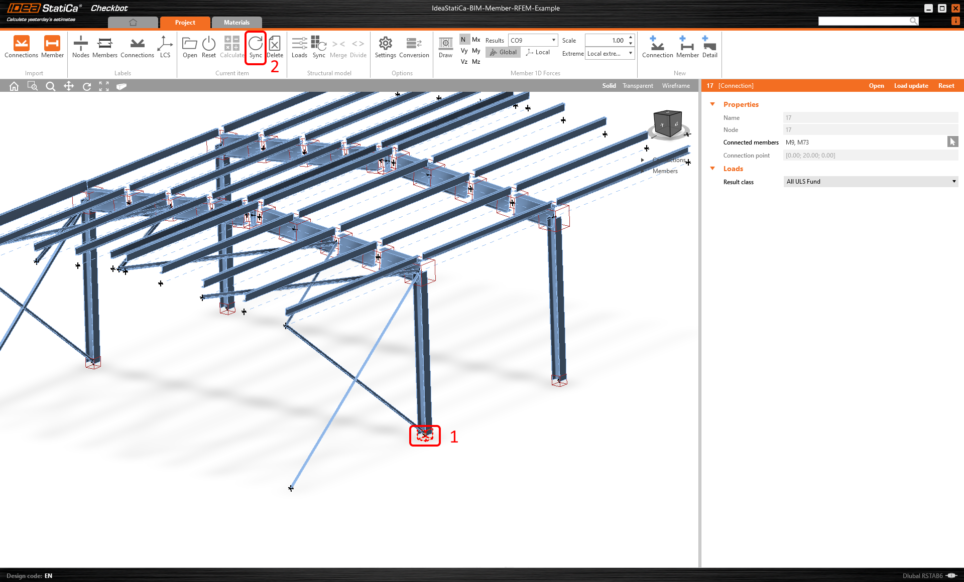
The Checkbot project will be updated, member (and connections) design is preserved, but the results will be invalidated. You can see that the column is now updated - matching the change in the FEA model.
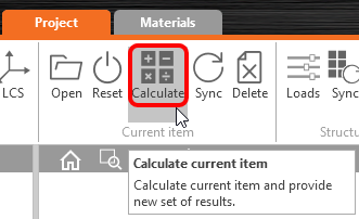
Simply code-check the highlighted member again by selecting Calculate from the Current item panel. Please remember that bigger changes in the model might require additional validation steps with the affected members (as above).
If the members do not give the desired results, then you can open them again to optimize the design (i.e. strengthen if they fail the code-check or lighten if the utilization is too low).
You have successfully linked RFEM/RSTAB with IDEA StatiCa Member via Checkbot.
Read more about the known limitations of the RFEM/RSTAB BIM link.