The different verifications required by ACI 318-19 are assessed based on the direct results provided by the model. Verifications are carried out for concrete strength, reinforcement strength, and anchorage (bond shear stresses).
The concrete strength in compression is evaluated as the ratio between the maximum Equivalent principal stress fc,eq (also σc,eq in previous text) obtained from FE analysis and the limit value f'c,lim.
Equivalent Principal Stress expresses the equivalent uni-axial stress for a general tri-axial stress state.
\[f_{c,eq} = \sigma_{c3} - \sigma_{c1}\]
The fc,eq value can, therefore, be directly compared with uniaxial strength limits. This expression is derived from the implementation of the Mohr-Coulomb plasticity theory, conservatively assuming the angle of internal friction φ = 0°.
The strength of the reinforcement is evaluated in both tension and compression as the ratio between the stress in the reinforcement at the cracks fs and the specified limit value fy,lim.
\[f_{y,lim} = \phi_{s} \cdot f_{y}\]
The bond shear stress is evaluated independently as the ratio between the bond stress τb calculated by FE analysis and the bond strength fbu.
Although the bond strength is not explicitly defined in ACI 318-19, the calculation of the development length can be found in Section 25.4.2. However, since the bond strength is the basic input for determining the development length, see R25.4.1.1 and ACI Committee 408 1966, the bond strength can be calculated as follows:
Let us assume that if we anchor the reinforcement bar into a concrete block to the development length ld or greater, pulling out the reinforcement will lead to rupture of the reinforcement and not to pulling out of the concrete. This can be written with the following formula.
\[\pi\cdot d_{b} \cdot l_{d} \cdot f_{bu}=f_{y}\cdot A_{s}\]
where:
db is the diameter of the reinforcement bar, ld is the development length, fbu is the bond strength, fy is the yield strength of the reinforcement, and As is the area of the reinforcement rebar.
From the preceding, the formula for calculating bond strength can be easily derived:
\[f_{bu}=\frac{f_{y}\cdot A_{s}}{\pi\cdot d_{b} \cdot l_{d} }\]
The development length ld is then determined according to ACI 318-19 Table 25.4.2.3 as follows:
\[l_{d}=\left( \frac{f_{y}\cdot\psi_{t}\cdot\psi_{e}\cdot\psi_{g}}{C\cdot\lambda\sqrt{f'_{c}}} \right)\cdot d_{b}\]
where:
C = 25 (2.1 for metric) for no. 6 and smaller bars and deformed wires, C = 20 (1.7 for metric) for no. 7 and larger bars, λ = 1.0 for normal weight concrete, ψt, ψe, ψg are determined according to ACI 318-19 Table 25.4.2.3.
Only uncoated or zinc-coated (galvanized) reinforcement is supported, so ψe = 1.0. ψg is automatically determined from the reinforcement grade, and ψt is automatically derived from the position of the reinforcement in the model and from the direction of concreting that can be set in the application for each project item as follows.
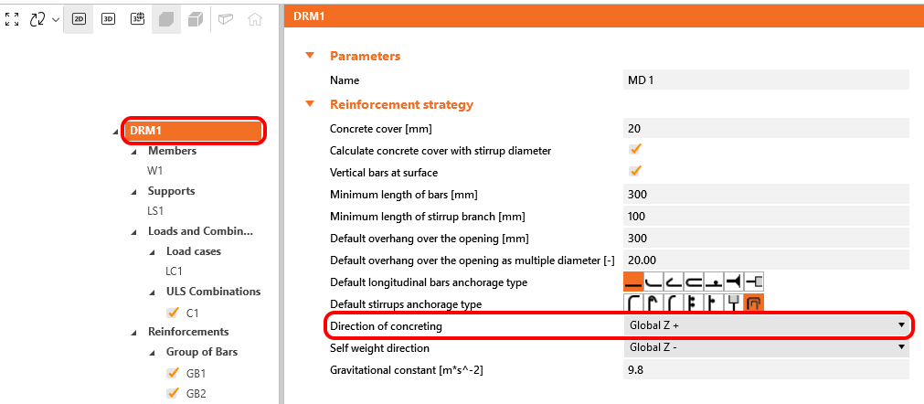
\[ \textsf{\textit{\footnotesize{Fig. 46\qquad Direction of concreting}}}\]
These verifications are carried out with respect to the appropriate limit values for the respective parts of the structure (i.e., in spite of having a single grade both for concrete and reinforcement material, the final stress-strain diagrams will differ in each part of the structure due to tension stiffening and compression softening effects).
Total force Ftot and limit force Flim
The total force Ftot is a result of the finite element analysis and can be defined in two ways.
\[F_{tot}=A_{s} \cdot f_{s}\]
where As is the area of the reinforcement bar and fs is the stress in the bar.
Or as a sum of the anchorage force Fa and the bond force Fbond.
\[F_{tot}=F_{a}+F_{bond}\]
where Fa is the actual force in the anchorage spring and Fbond is the bond force that can be obtained by integrating the bond stress τb along the length of reinforcement bar l.
\[F_{bond}=C_{s} \cdot \int_{0}^{l}\tau_{b}\left( x \right)dx\]
Cs is the circumference of the reinforcement bar.
The limit force Flim is the maximum force in the element of the rebar considering the strength of the rebar and also anchoring conditions (bond between concrete and reinforcement and anchorage hooks, loops, etc.).
\[F_{lim}=min\left( F_{lim,bond}+F_{au},F_{u} \right)\]
\[F_{u}=f_{y,lim}\cdot A_{s}\]
\[F_{au}=\beta\cdot f_{y,lim}\cdot A_{s}\]
\[F_{lim,bond}=C_{s}\cdot l \cdot f_{bu}\]
where Cs is the circumference of the reinforcement bar, and l is the length from the beginning of the rebar to the point of interest.
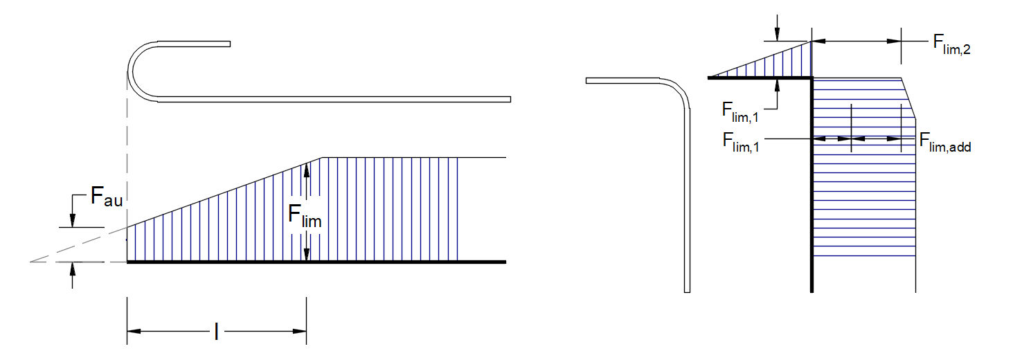
\[ \textsf{\textit{\footnotesize{Fig. 47\qquad Definition of the limit force Flim}}}\]
\[F_{lim,2}=F_{lim,1}+F_{lim,add}\]
where Flim,add is the additional force calculated from the magnitude of the angle between neighboring elements. Flim,2 must be always lower than Fu.
The available anchorage types in CSFM include a straight bar (i.e., no anchor end reduction), 90-degree hook, 180-degree hook, perfect bond, and continuous bar. All these types, along with the respective anchorage coefficients β, are shown in Fig. 48 for longitudinal reinforcement. The values of the adopted anchorage coefficients are derived from the comparison of the equation from section ACI 318-19 25.4.3.1 and equations taken from section ACI 318-19 25.4.2.3. It should be noted that, in spite of the different available options, CSFM distinguishes three types of anchorage ends: (i) no reduction in the anchorage length, (ii) a reduction of 30% of the anchorage length in the case of a normalized anchorage, and (iii) perfect bond.

\[ \textsf{\textit{\footnotesize{Fig. 48\qquad Available anchorage types and respective anchorage coefficients for longitudinal reinforcing bars in CSFM:}}}\]
\[ \textsf{\textit{\footnotesize{(a) straight bar; (b) 90-degree hook; (c) 180-degree hook; (d) perfect bond; (e) continuous bar}}}\]
The anchorage coefficient for stirrups is always - β = 1.0.
In order to comply with ACI, the anchorage spring should be used in the calculation, the anchorage spring is modified by the β coefficient so the user must use one of the available anchorage types when defining the reinforcement start and end conditions.