How to manage pile cap design
What is a pile cap?
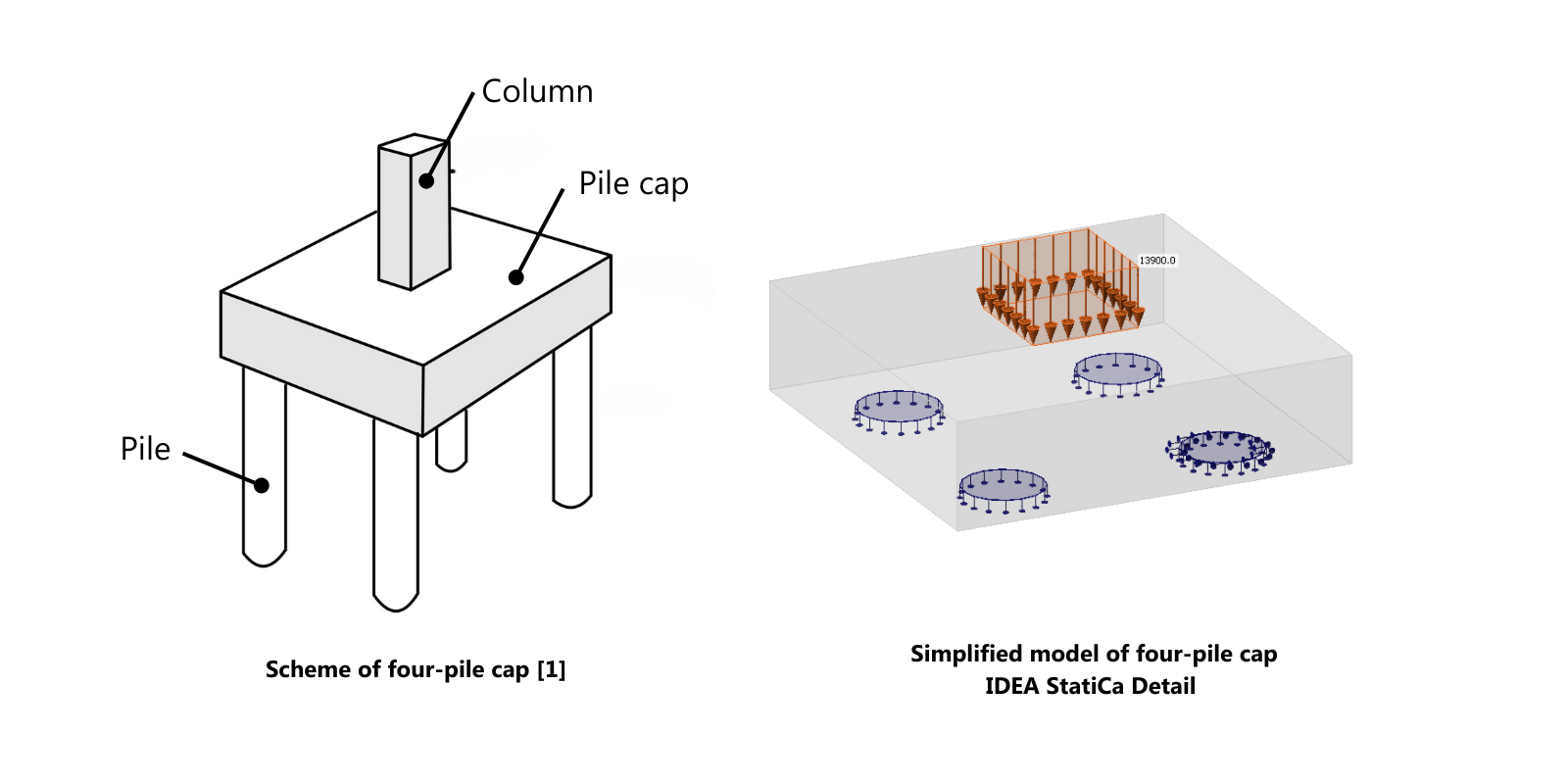
A pile cap is a concrete mat widely used in the foundations of buildings, bridges, marine structures, and other heavy infrastructure where soil conditions are not ideal for shallow foundations. Its primary function is to distribute the loads from the superstructure into the piles, which in turn transfer the loads to the deeper, more stable soil or rock layers.
We can distinguish types of piles according to several criteria:
- Based on material (Concrete, steel, timber, ...)
- Based on installation method (Driven, drilled/bored, screw, etc.)
- Based on function (End-bearing, friction, combination, etc. )
- Special types (Micropiles, sheet piles, ...)
The correct design of piles is particularly important for verifying settlement, which is then taken into account in the design of the superstructure. The design depends mainly on the environment, i.e., the soil and the maximum required settlement (which is specified according to the type of superstructure and the overall design). This is usually the geotechnical engineer's responsibility.
Now, we'll go back a little bit to pile cap design. As mentioned, a pile cap is quite often designed with reinforced concrete, and that is where the structural engineer comes into play as they need to design the pile cap to resist the forces from the superstructure and determine how the forces are distributed to the individual piles.
How to design a pile cap
In general, we have several points to consider that affect the overall outcome:
- Material: Typically made of reinforced concrete.
- Thickness: The thickness of a pile cap foundation depends on the loads it needs to carry and the spacing of the piles.
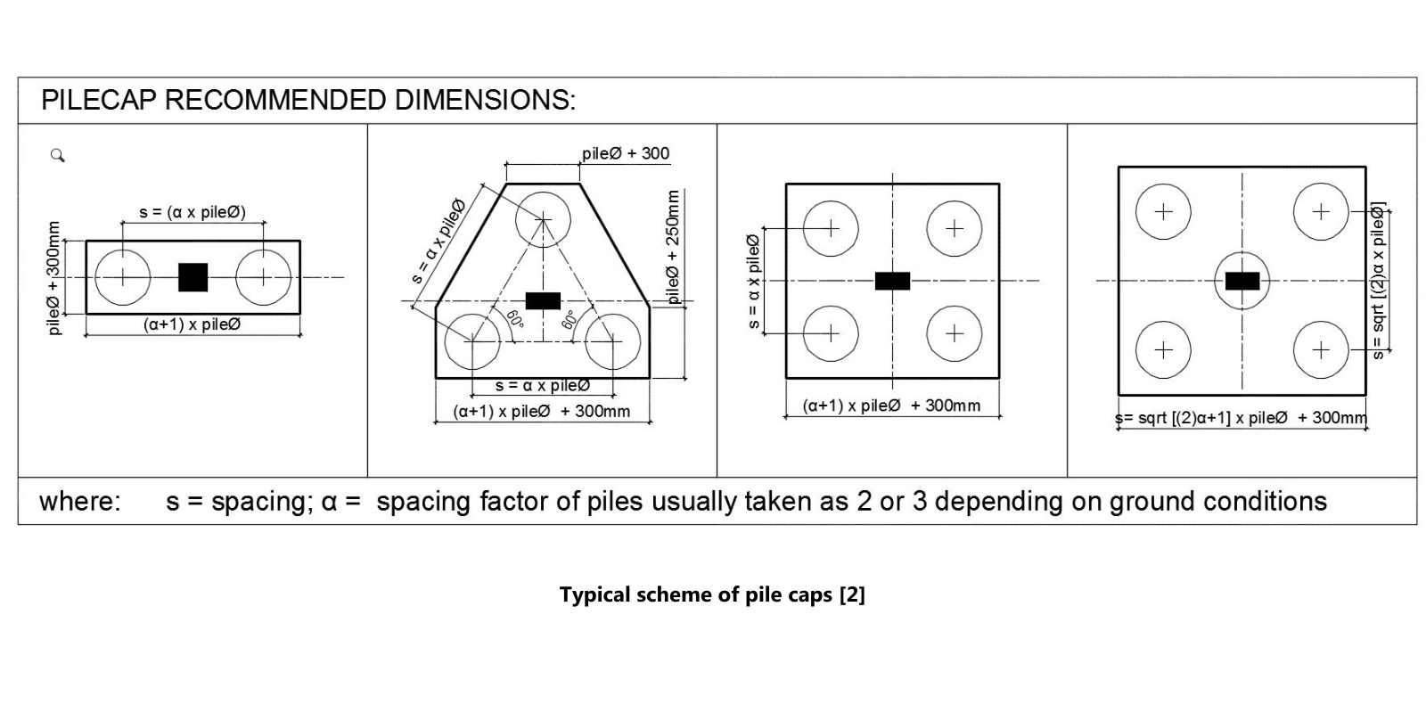
- Shape and size: The shape and size are determined by the arrangement of the piles and the nature of the loads from the structure. Common shapes include rectangular, square, and triangular.
- Pile cap reinforcement: Adequate reinforcement is provided to handle the bending moments and shear forces.
- Alignment: Proper alignment and positioning of piles are crucial during construction to ensure that the pile cap can effectively transfer loads.
Okay... we know exactly what we need to design, but how and what are the options?
The empirical approach and Strut-and-Tie Method
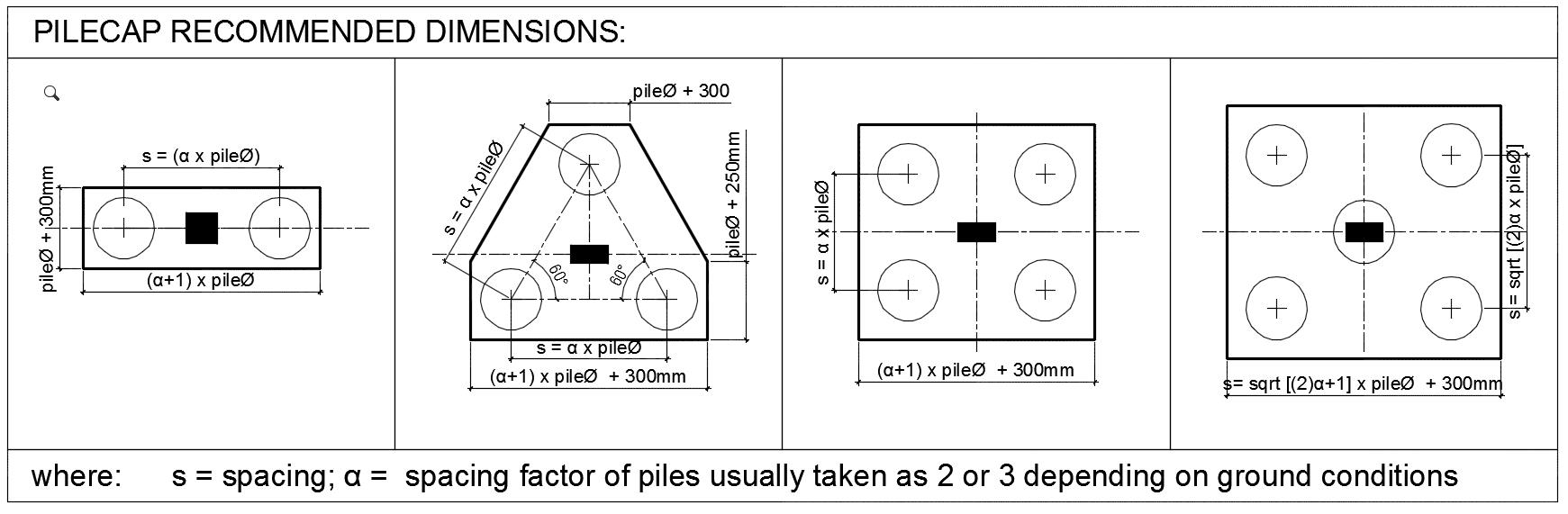
The simplest is to start with guides based on empirical relationships between pile alignment, thickness, dimensions, and others, and then proceed with the design of the reinforcement using the Strut-and-Tie Method.
The Strut-and-Tie Method (STM) is a design approach used in structural engineering, particularly for the design of reinforced concrete structures. It is especially useful for analyzing and designing regions of concrete structures where the traditional assumptions of beam theory do not apply, such as areas with complex stress distributions, like discontinuity regions (D-regions) found around openings, supports, and load application points. STM simplifies complex stress patterns into a model composed of simple, idealized elements: struts, ties, and nodes.
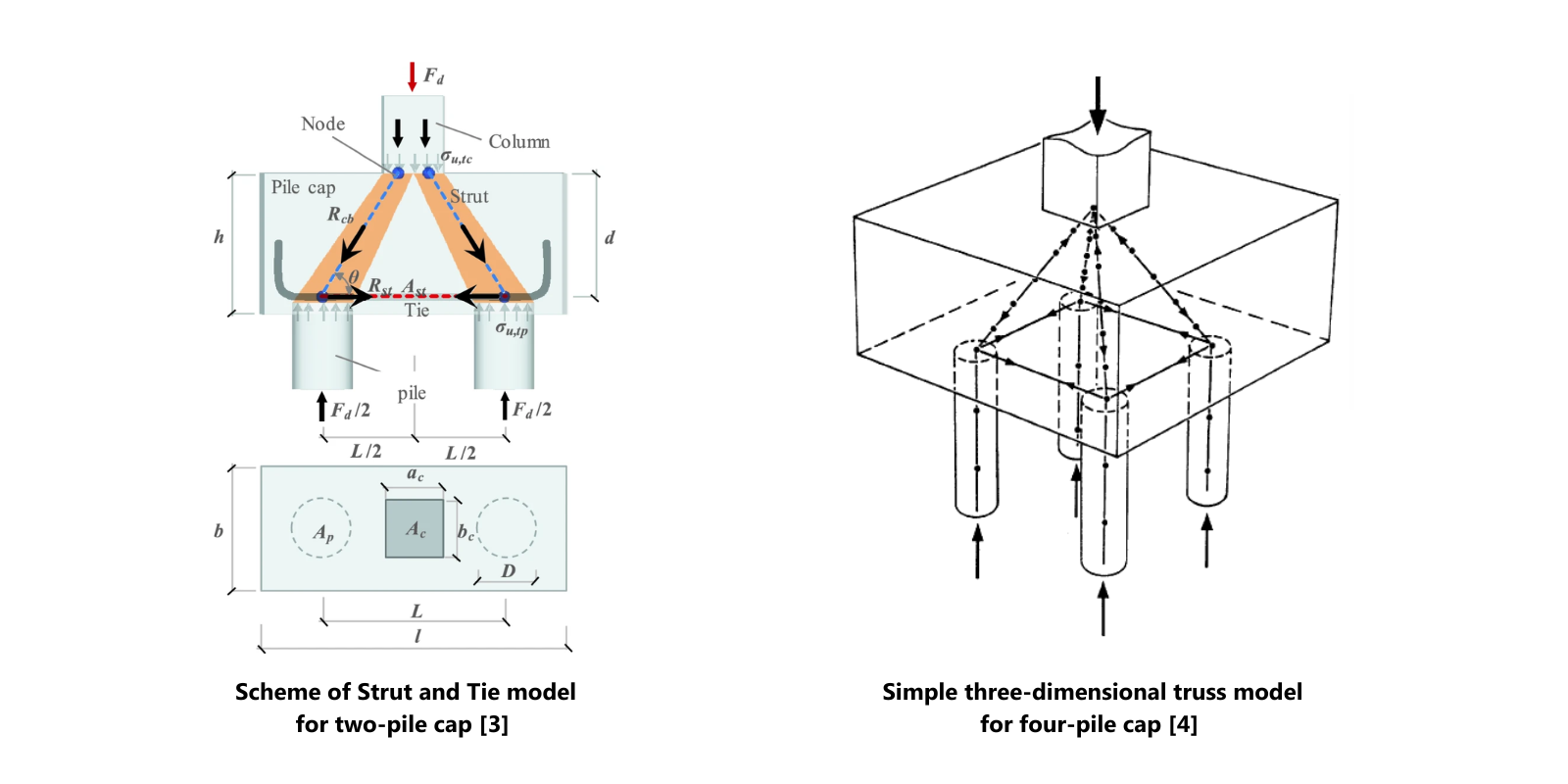
To apply the Strut-and-Tie Method, start by developing the strut-and-tie model by creating an idealized truss model that approximates the flow of forces within the D-region, involving the identification of the locations and orientations of struts, ties, and nodes. Then, calculate the forces in each strut and tie by analyzing the strut-and-tie model. Following this, ensure that each strut, tie, and node is capable of carrying the calculated forces by checking the capacity of concrete struts for compression, reinforcing steel ties for tension, and nodes for the transfer of forces.
The Strut-and-Tie Method is a powerful tool in structural engineering, especially for complex regions in concrete structures. However, it has several disadvantages:
- Complexity and skill requirements: Designing using STM requires a high level of expertise and experience. It can be complex and difficult for engineers to determine the ST model at the beginning.
- Time-consuming: Developing an accurate strut-and-tie model and performing the necessary calculations can be time-consuming.
- Simplification assumptions: STM relies on simplifications and idealizations of the actual stress distribution. These assumptions may not perfectly reflect the real behavior of the structure.
- Iterative nature: The process can be iterative, requiring multiple adjustments to the model to achieve an acceptable design. This iterative nature can add to the complexity and time required.
- Conservatism: The method can sometimes lead to overly conservative designs, resulting in the use of more material than might be necessary, which can increase costs.
- Not universal enough: Determining the correct ST model for untypical shapes can be tricky or even impossible.
Further calculations and verifications, such as Punching Shear Resistance and Detailing checks, need to be added.
The CSFM approach
An alternative could be to use more advanced finite element methods such as CSFM implemented in IDEA StatiCa Detail.
CSFM stands for Concrete Stress Field Method. This is a method used in structural engineering for the analysis and design of reinforced concrete structures. The method is based on the concept of the stress field, which represents the distribution of internal stresses within a concrete element. It takes into account the interaction between concrete and reinforcement. Despite its simplicity, the method provides a very realistic description of the response of a concrete structure both in the Ultimate Limit State (ULS) and Serviceability Limit State (SLS). All the basic assumptions are explained in the article CSFM explained.
2D CSFM has already been validated, not only by theoretical and experimental verifications, but also by existing structures and their use in practice. For example, see some of these Case Studies.
Example 1 - Concrete pile cap with anchoring
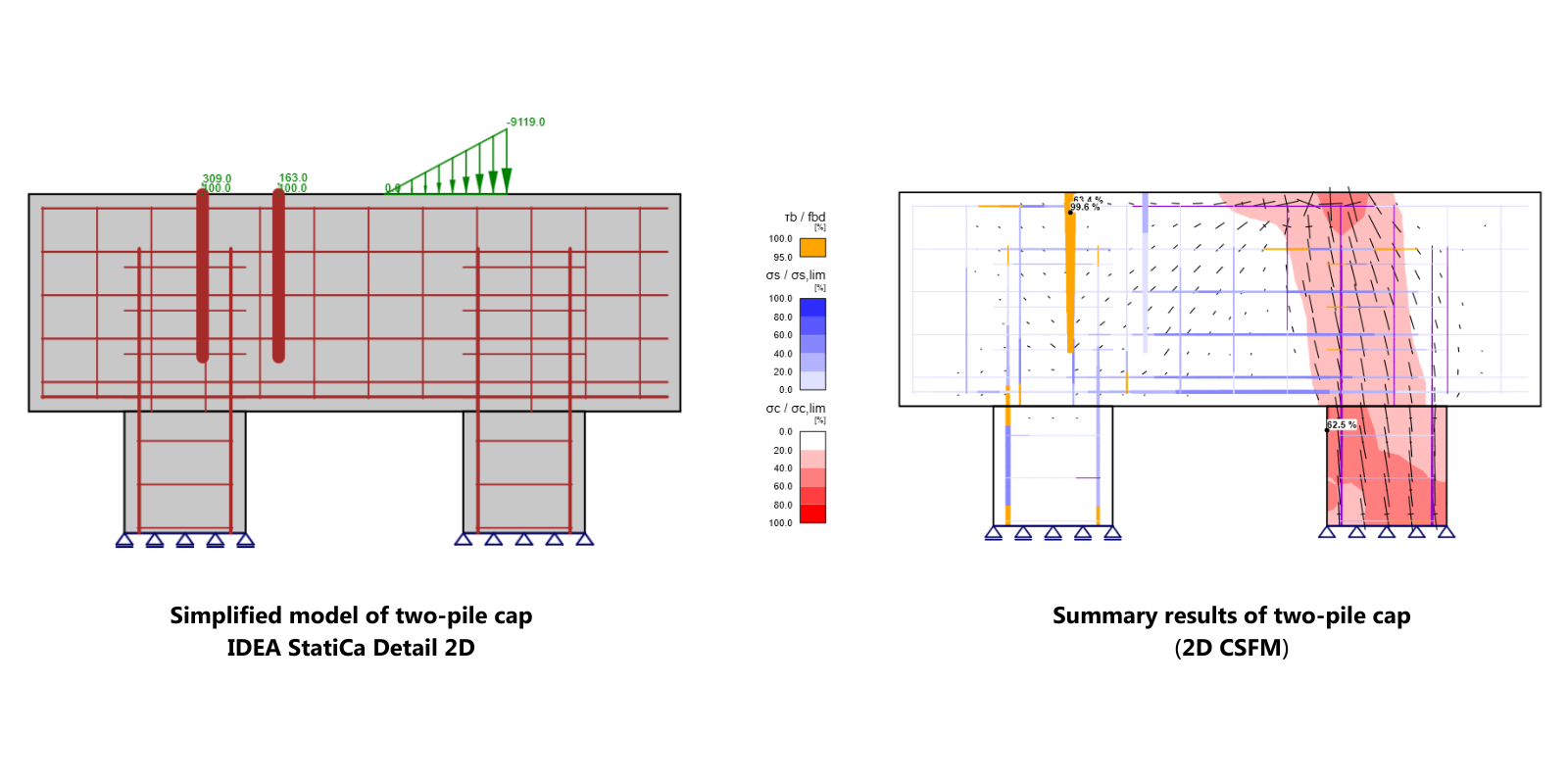
In the first example below, you can see the design of the two-pile cap including the anchoring of a steel column. The design was done, including all ULS and SLS assessments, using 2D CSFM in IDEA StatiCa Detail 2D. In the picture, you can see the basic model and summary results. Detailed modeling workflow and also complex results can be found in the already streamed webinar.
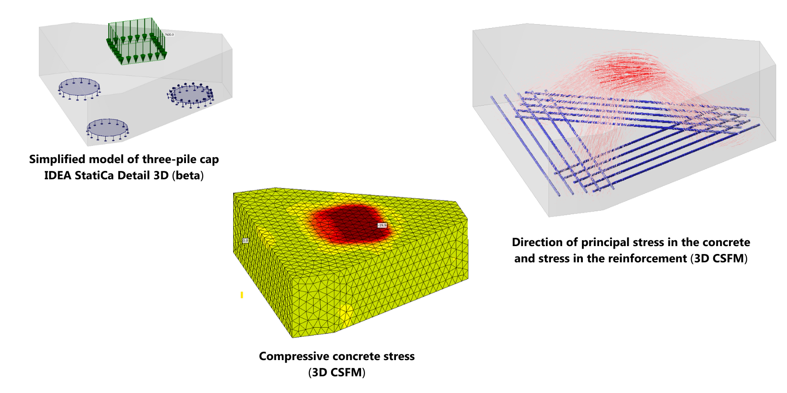
Not everything (e.g., How do we calculate the volume of concrete for a 3-pile group cap?) can be simplified using combinations of 2D tasks – which is why we are developing 3D CSFM. This is in BETA at the moment and is publicly available for you to test using this link. As more and more verification studies are completed, we will be nearer to a formal release. Although primarily the most typical scenario will be focused on anchoring and footing, this article gives you a good idea of the expanded application of the 3D approach as it develops over time.
Example 2 - Triangular concrete pile cap foundation
In the next picture below, you can see an example of a triangular pile cap design with three piles, which could be suitable for 3D CSFM because simplification to a 2D solution would not correspond to reality. With 3D CSFM, we will not only be able to design the tension reinforcement and check if the concrete can properly transfer all the compression, but we will also be able to see how the load is distributed to the individual piles.
The biggest advantages of the method are:
- Automation: In IDEA Statica, the finite element model is created automatically. There is no need for lengthy definitions of constraints, and compared to STM, there is no need to know the structure's behavior in advance.
- Accurate stress representation: Provides a more accurate representation of stress distributions in complex regions, compared to simpler methods.
- Universal enough: Can be applied to a wide range of structural elements and load conditions.
- Enhanced safety: Helps in designing safer structures by accurately predicting potential failure modes.
Conclusion
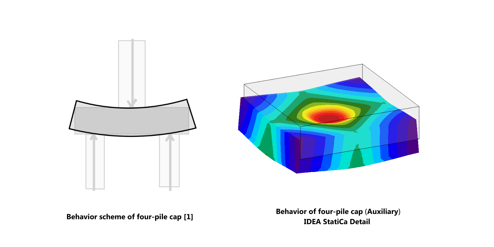
When it comes to the design of concrete pile caps, it is clear, at first glance, that the pile cap is another case of a discontinuity region. Although we have some basic principles in our codes and manuals on how to proceed, we need to understand more about the behavior of the structure, especially if we deal with atypical shapes and alignments. Additionally, more than with other parts of the structure, pile caps can sometimes be a problem when flipping into a 2D task, and it is necessary to solve the problem spatially for a correct judgment. Moreover, the fact this is part of the structure on which the rest of the structure literally stands makes the task even more significant and requires attention the attention it deserves.
Both CSFM and STM are used for complex regions in concrete structures. While STM simplifies the region into a truss-like model with discrete struts, ties, and nodes, CSFM models the continuous stress distribution within the concrete. In summary, the Concrete Stress Field Method (CSFM) implemented in IDEA StatiCa Detail is a sophisticated tool for the design and analysis of reinforced concrete structures, offering detailed insights into stress distributions and accurate results for both 2D and 3D tasks.
Resources:
There are many resources on CSFM in the IDEA StatiCa Support Centre (including theoretical background, knowledge base articles, and verifications), as well as third-party studies and articles that are freely available on the Internet.
External picture sources:
[1] https://www.eigenplus.com/design-steps-of-pile-foundation/
[2] https://www.thestructuralworld.com/wp-content/uploads/2018/07/PilecapDimensions.jpg
[3] https://www.nature.com/articles/s41598-022-14416-2
[4] https://www.linkedin.com/pulse/how-determine-pile-cap-depth-dr-subramanian-narayanan/
Take the latest IDEA StatiCa for a test drive today