Bridge column (EN)
1 New project
Open IDEA StatiCa and select the Member application.

Create a new project (1), type its name, and select a folder where it will be saved. Then, choose the project type Concrete (2), and change the Concrete grade and Design working time (3). Choose the type of topology (4). Define the high of the column to 22 m (5). Click on the arrow (6) to set the cross-section. Select the Advanced (7) tab then I shape with haunch (8). Chance the dimensions (9) and click on the OK button (10). Finally, click on Create project (11).

2 Design
The column is now created with related members. Delete all Related members.

The modification of supports is needed. To do that, select JOINT1 and modify the support. After that select the second JOINT2 and change the support too. Degrees of freedom are defined in the figure below.

The next step is to define the reinforcement layout. Select the analyzed member AM1 (1) and click on the Rebar assembly (2) button. Then select Longitunidal bars (3) -> New on all edges (4).

Set the diameter, maximum distance, and cover.

The last item to be defined is the Load. Set the load case. Click on the plus button to add a new Point load.

3 Check
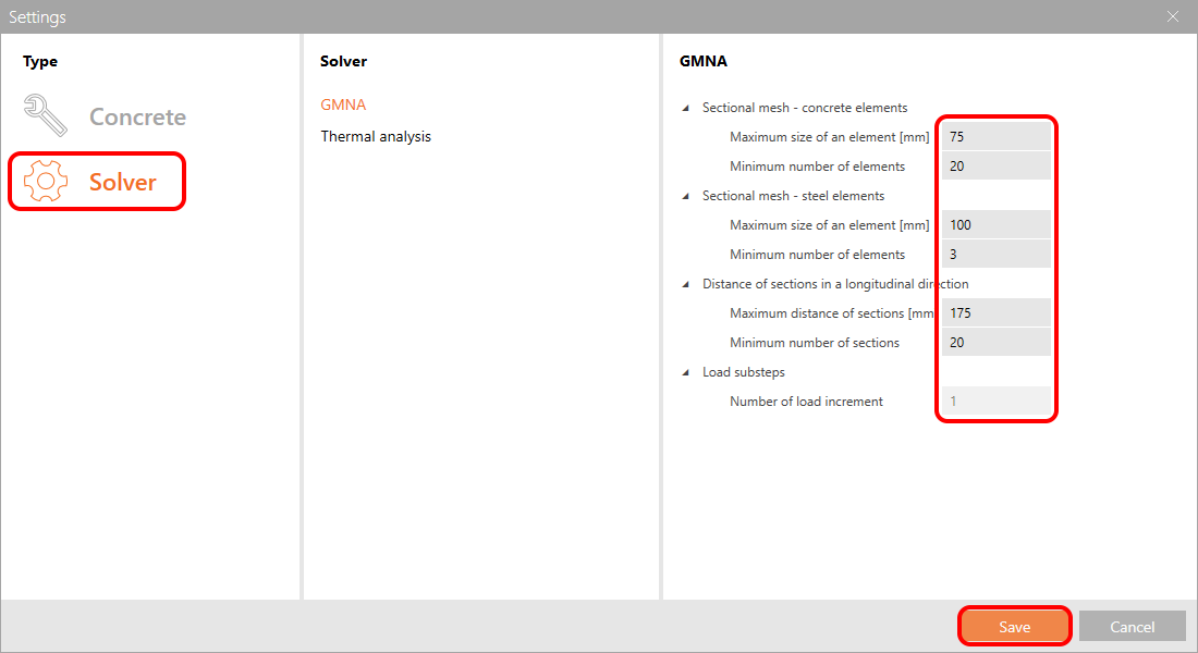
The model is done. Before calculating, go to Settings to Chapter 3 and set αcc to 0.85.

The Solver settings need to be adjusted due to the size of the model.
Then you can get the program to do the Linear analysis. You will receive the internal forces, displacement, and reaction, or you can jump to the RCS application by using the Detailed button to do the Code-checks.
The GMNIA does not take into account shear and torsion. The shear check has to be done by using the linear analysis and the RCS application.
We will skip the Linear analysis. You can find more information in this tutorial: Concrete slender column (EN).
Select the GMNA type of analysis and proceed to MNA - Materially non-linear analysis.
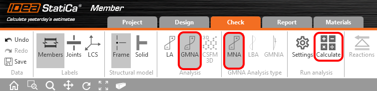
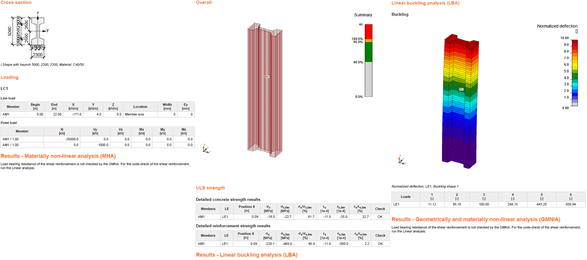
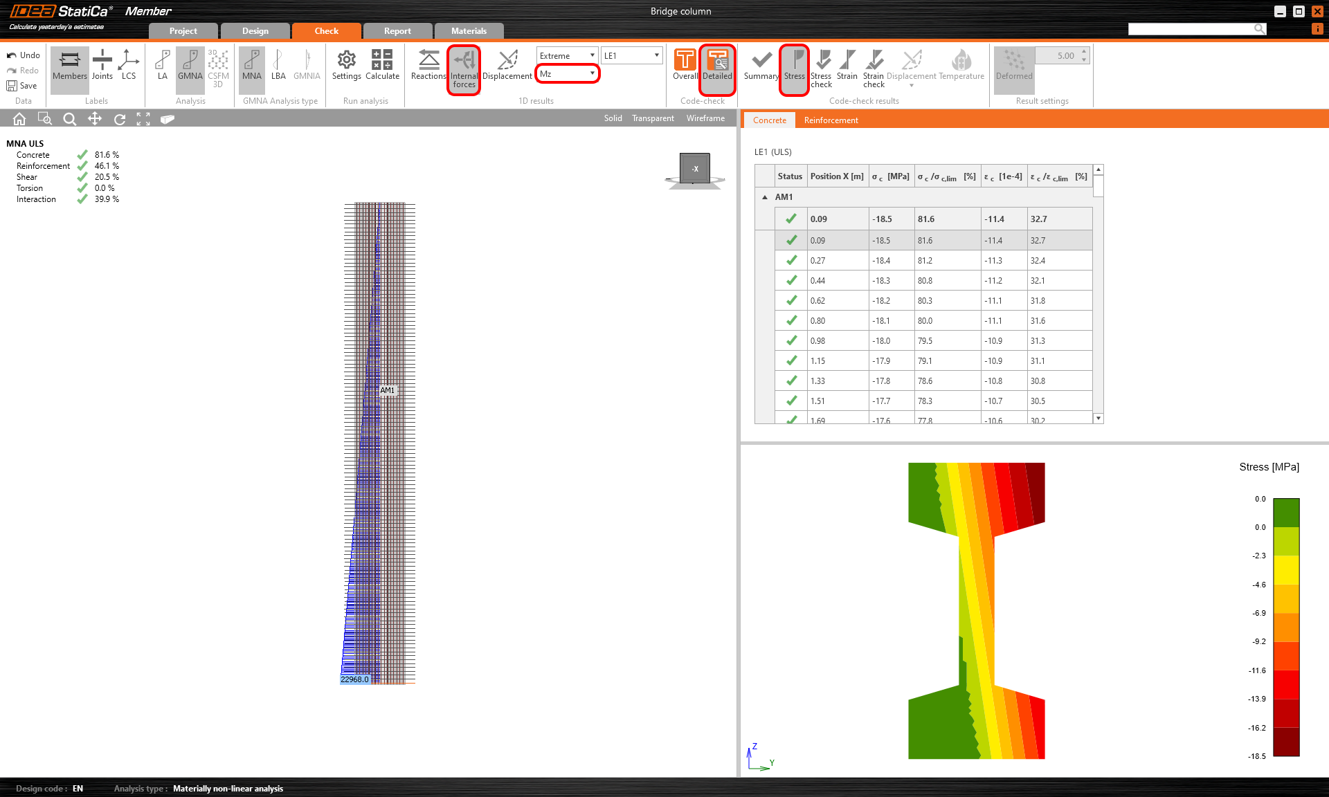
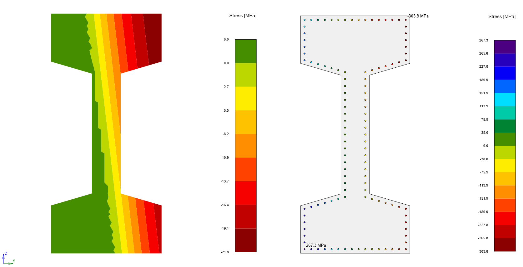
Once the calculation is completed. You can check the results. First, have the program displayed the bending moment Mz diagram. Then you can click on Detailed and Stress. Don't forget to choose the critical section. You will see the stress in the concrete.
Run the LBA - Linear buckling analysis.

When the calculation is completed set the Imperfection amplitude. The value of the amplitude is calculated according to EN 1992-1-1 article 5.2 (9).
To learn how to include creep read the linked article.
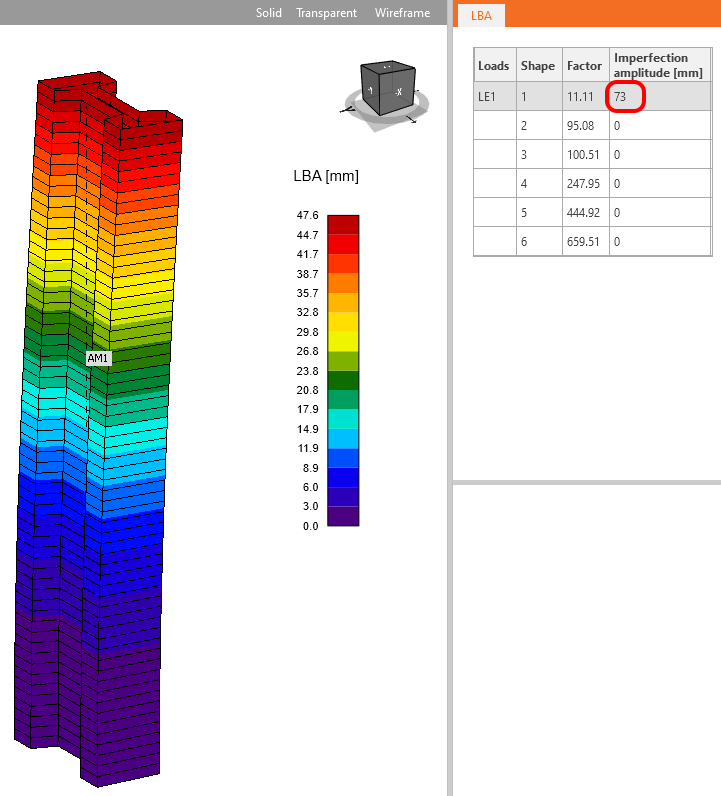
Always check the + and the - sign of the imperfection!
Start GMNIA - Geometrically and materially non-linear analysis with imperfections.

That was the last analysis type. You can check the results as well as in the MNA. Due to the second-order effect, you can see increased bending moments.
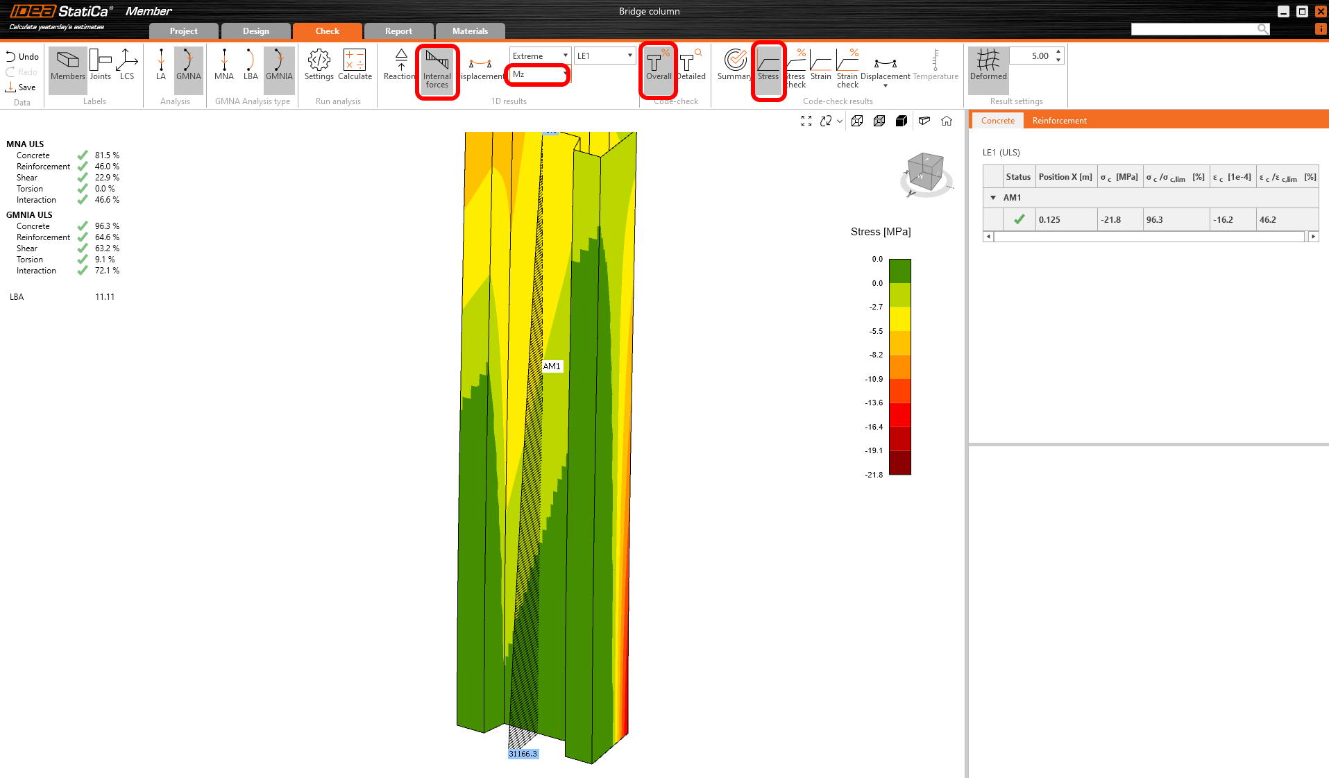
You can also check the stresses in concrete and in reinforcement. Again, don't forget to select the critical cross-section.
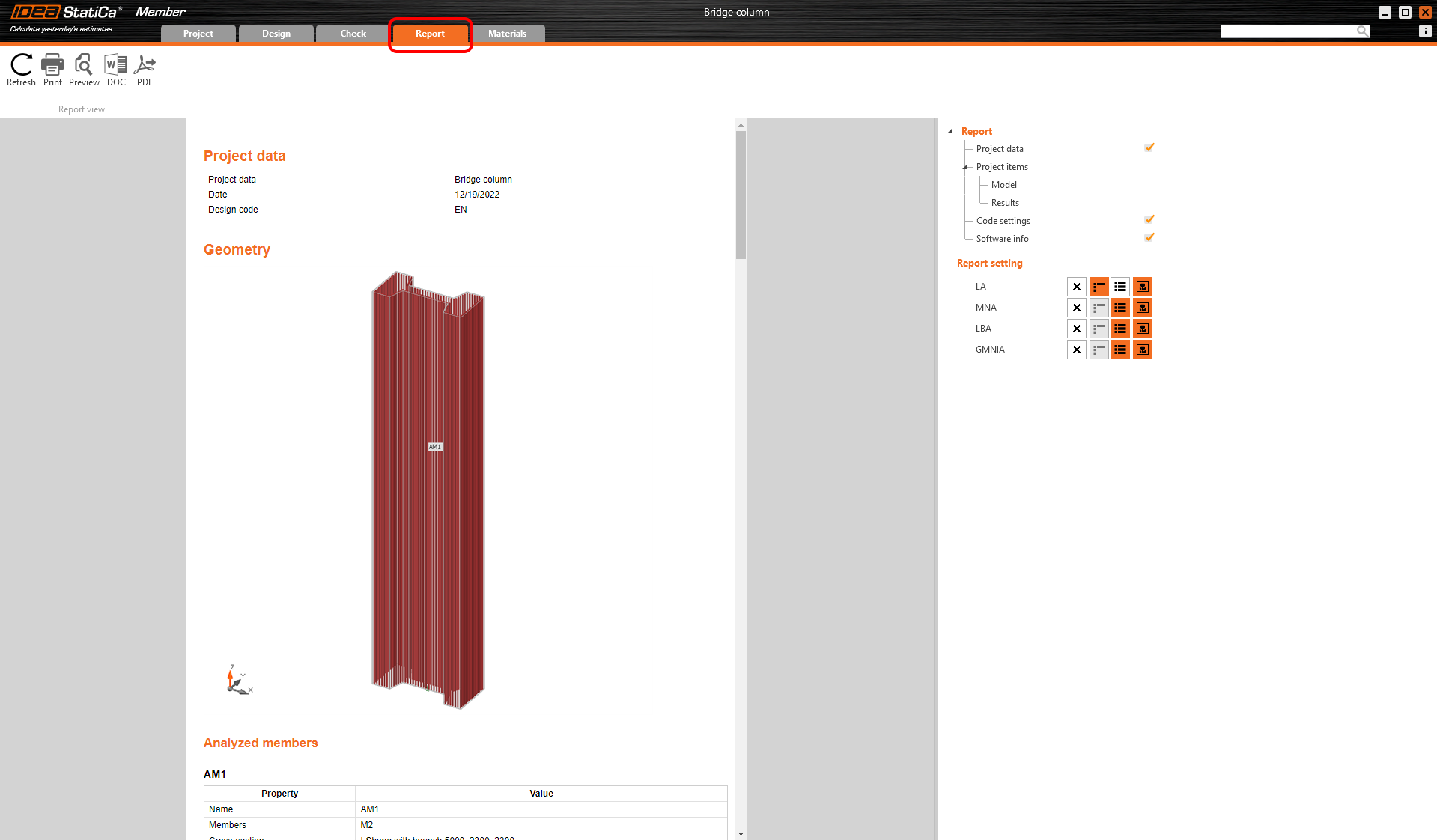
3 Report
Go to the report tab. Here the report can be printed.