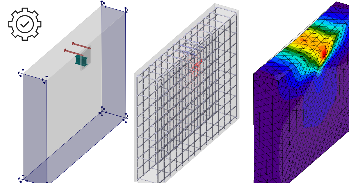
Detail 3D este, în esență, o extensie a aplicației Detail actuale, deja consacrate. Aceasta adaugă un nou tip de model 3D și, odată cu acesta, implementarea unei metode de calcul al câmpurilor de tensiuni în spațiul 3D, numită 3D CSFM. Calculele și verificările sunt implementate pentru Starea Limită Ultimă.
Înainte de a trece la descrierea funcționalităților Detail 3D, este util să menționăm existența fondului teoretic, unde puteți citi mai multe detalii tehnice despre entitățile individuale ale modelului și despre calculele propriu-zise.
În primul pas, utilizatorul poate selecta un nou tip de model pe ecranul inițial (în asistent), unde sunt disponibile mai multe șabloane și, desigur, opțiunea de a introduce un model de la zero.
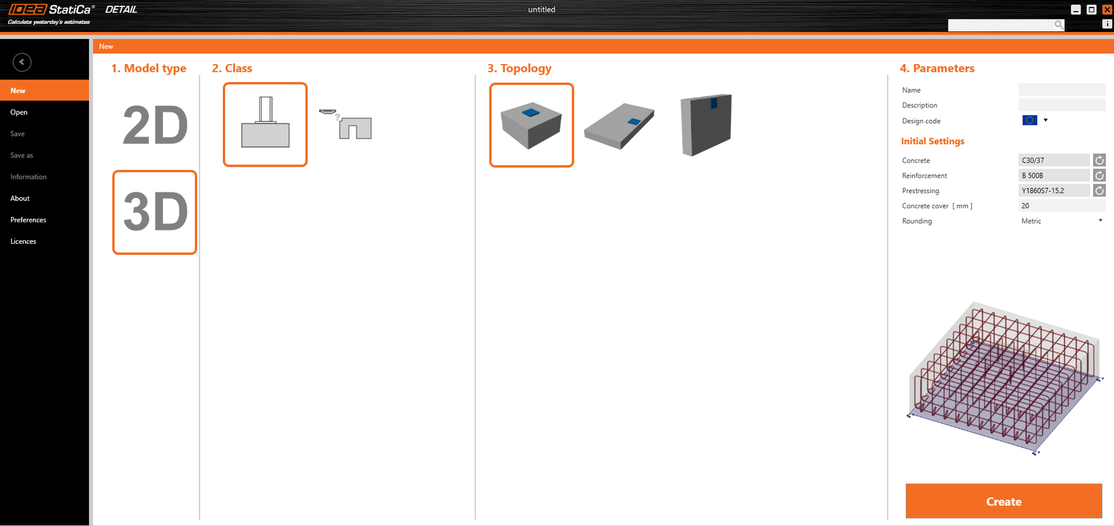
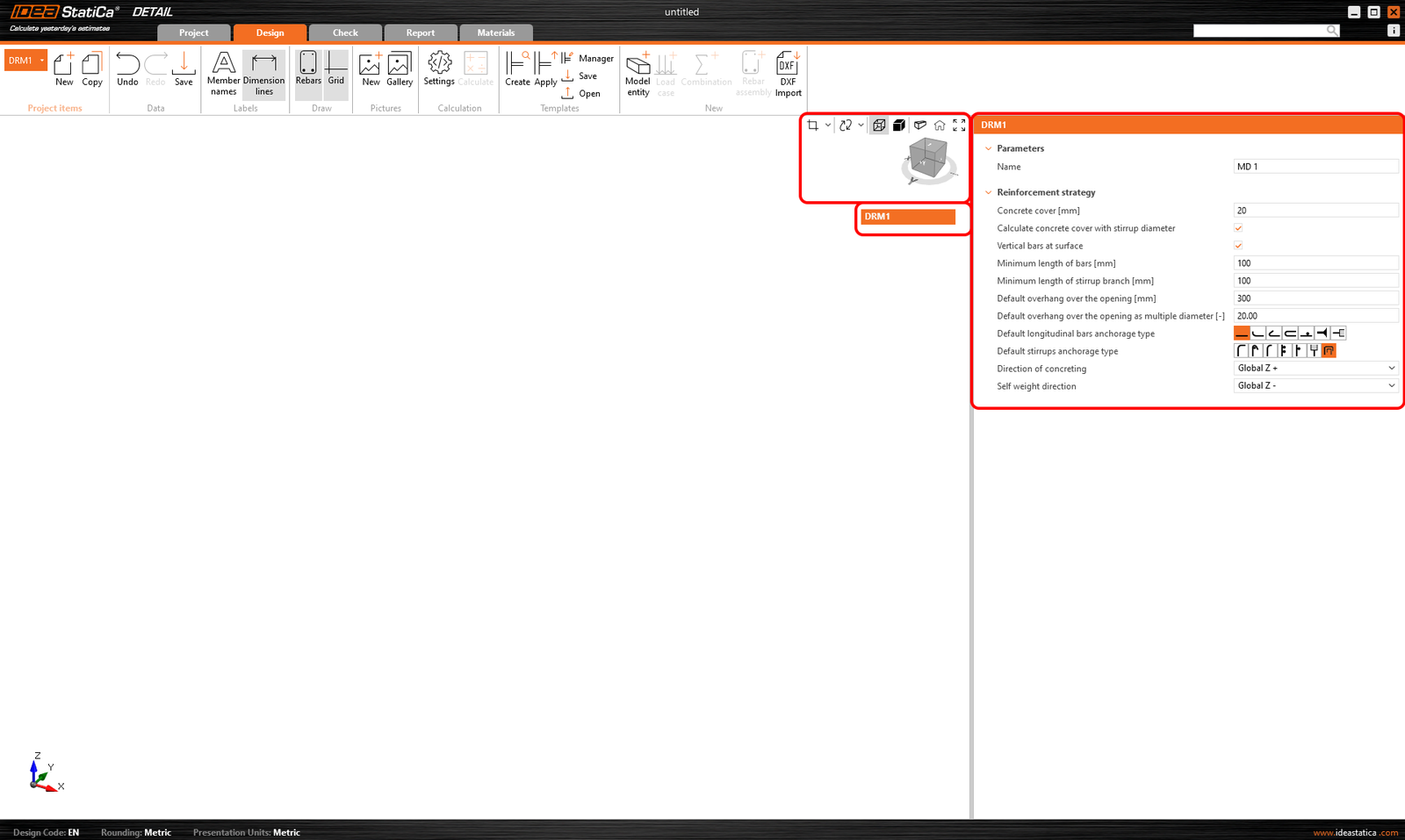
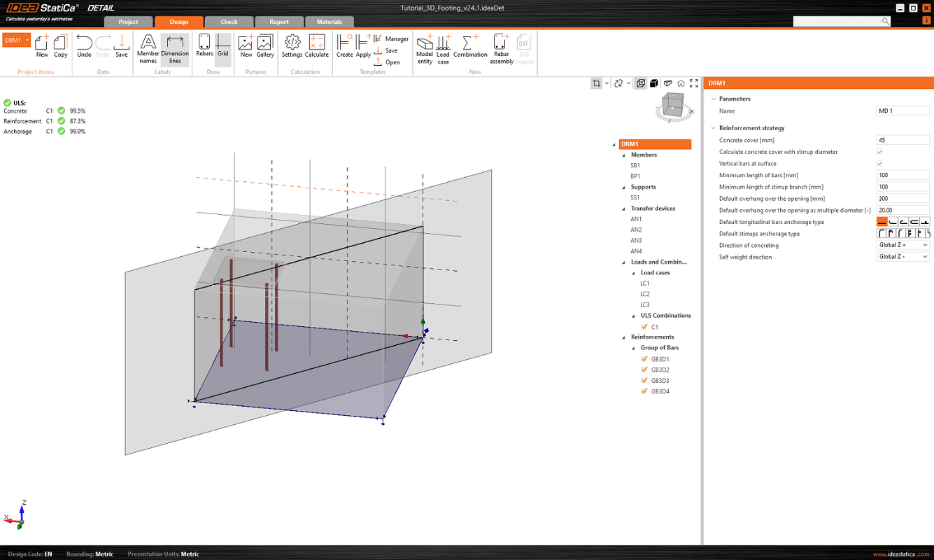
Ca și în cazul modelelor 2D, puteți edita setările inițiale în partea dreaptă, cum ar fi codul de proiectare, materialele și acoperirea cu beton.
După crearea unui model gol sau a unui model dintr-un șablon, sunt disponibile opțiunile familiare din mediul de modelare 2D.
Opțiunile pentru lucrul cu mai multe elemente de proiect se găsesc în bara de instrumente superioară, împreună cu butoanele standard Anulare/Refacere, opțiunile de vizualizare a etichetelor, controalele galeriei, setările de calcul și controalele de gestionare a șabloanelor.
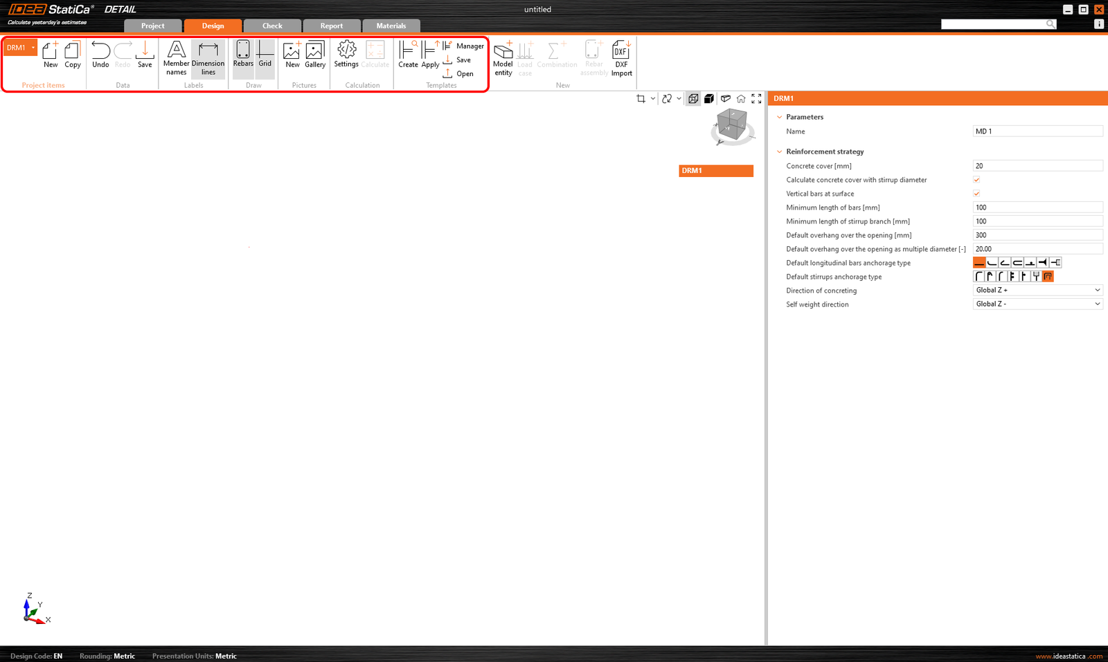
De asemenea, se inițializează arborele, al cărui prim element, numit implicit DRM1, conține setările implicite pentru elementul de proiect curent. Deasupra arborelui, puteți găsi instrumente pentru manipularea modelului.
Entități ale Modelului
Includem următoarele în categoria entităților Modelului în aplicația Detail:
- Elemente
- Reazeme
- Dispozitive de transfer al încărcărilor
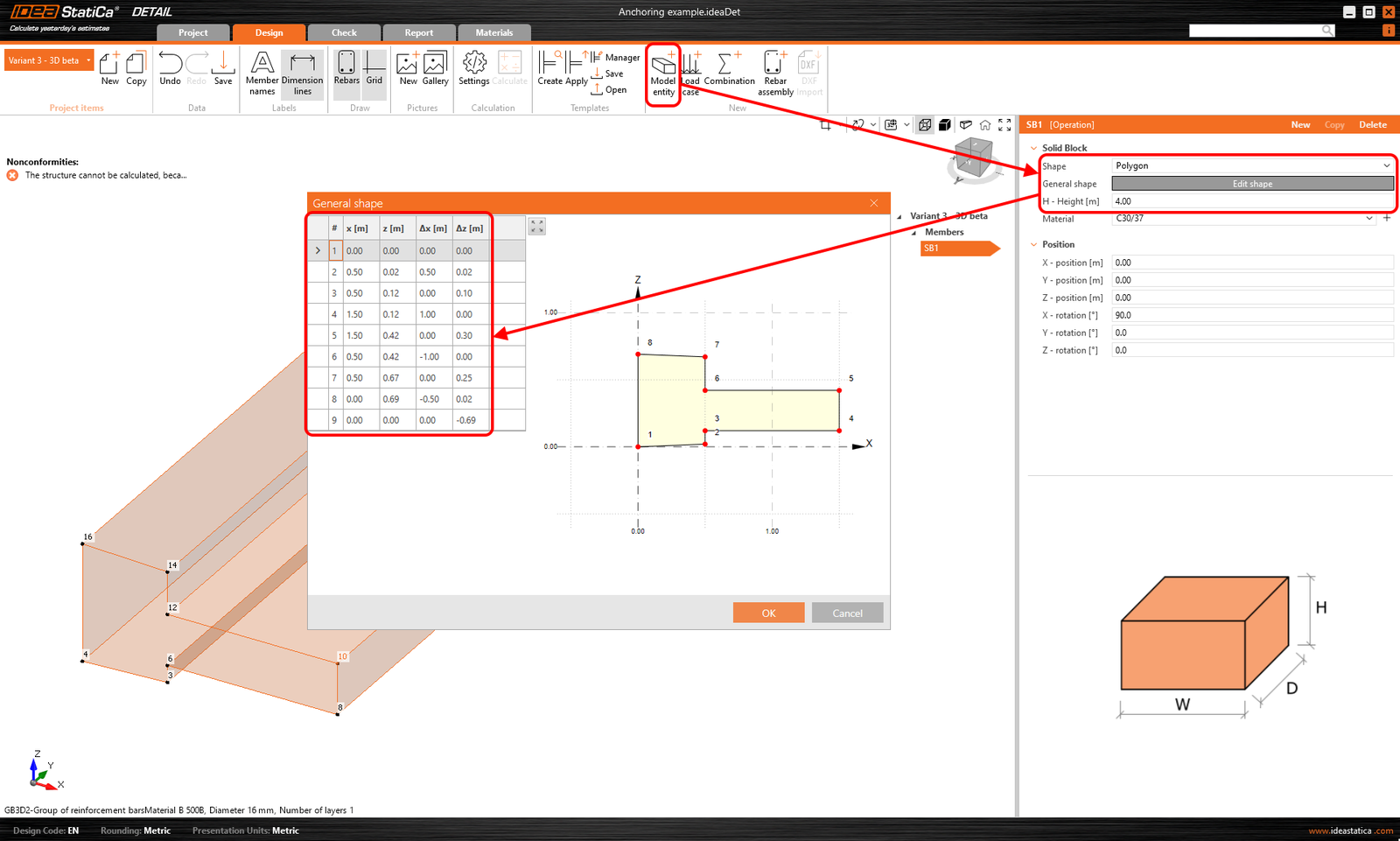
Poate fi introdus un singur element Member, care poate fi definit ca formă Dreptunghiulară sau Poligonală. O formă dreptunghiulară este definită prin trei dimensiuni, iar pentru opțiunea Poligon, forma în spațiul 2D este introdusă într-un tabel folosind coordonate, care pot fi apoi extrase în spațiu. Pentru a defini forma generală a unui poligon, coordonatele individuale pot fi completate în tabel sau se poate utiliza funcția copiere-lipire dintr-un program de calcul tabelar (cum ar fi Microsoft Excel).
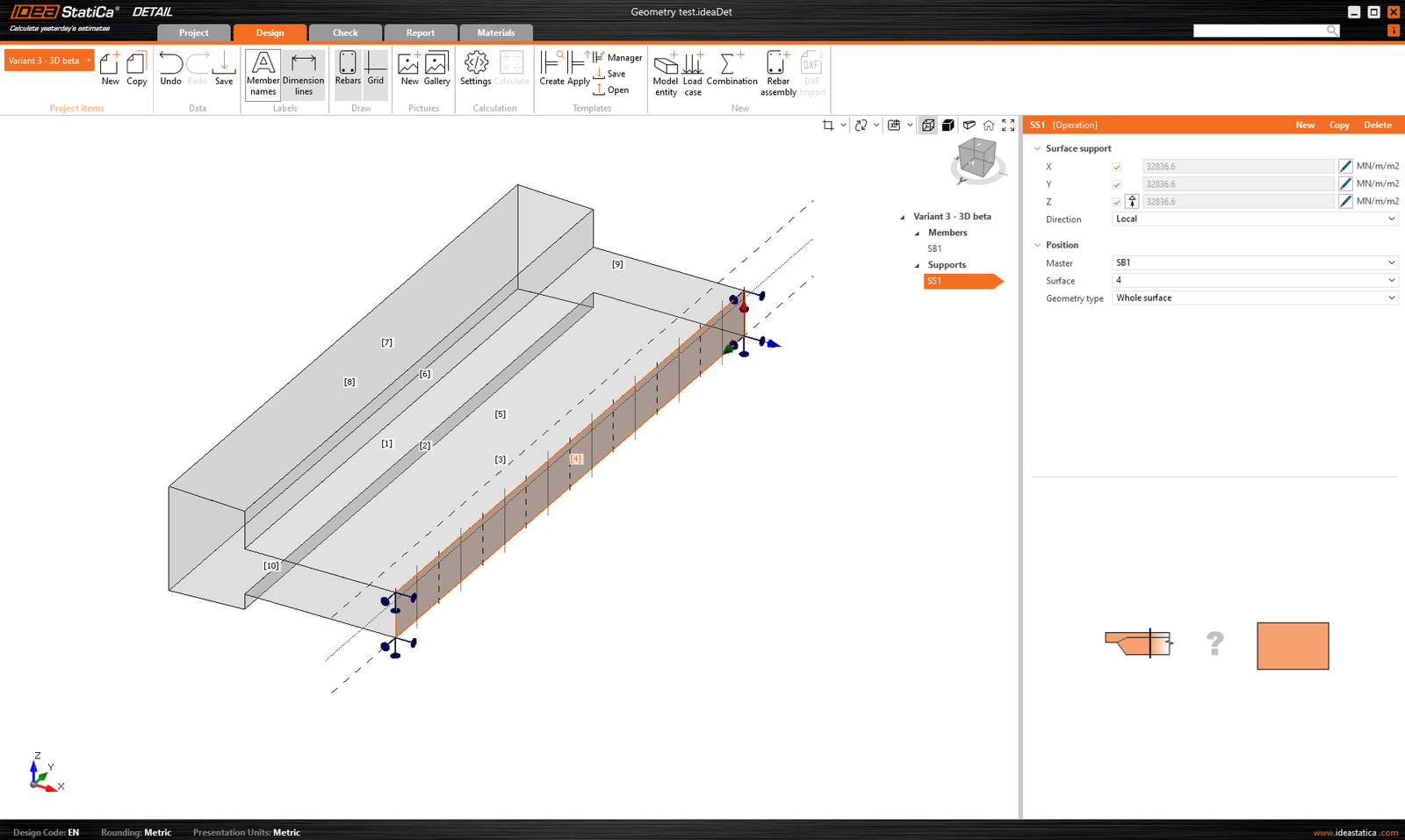
Rezemarea pe suprafață este utilizată pentru a reazema modelul. Acest tip de reazem poate fi specificat în două moduri - două tipuri de Geometrie.
- Suprafață întreagă
- Polilinie
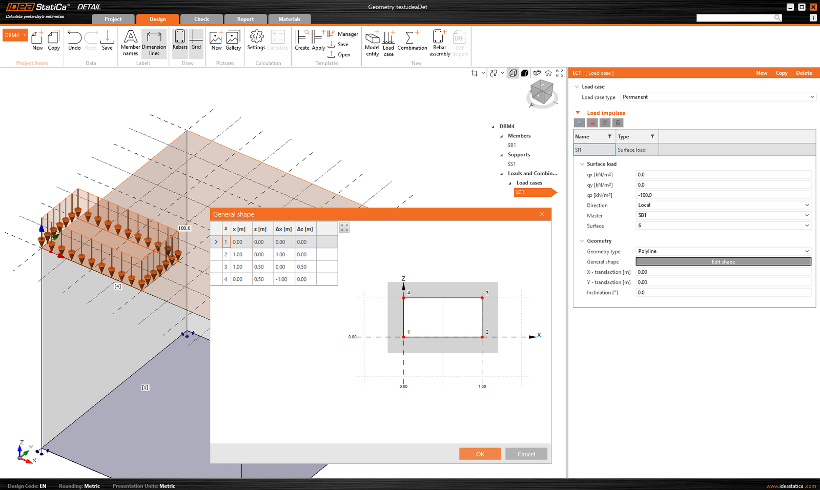
În ambele cazuri, trebuie să alegeți o suprafață de referință și, desigur, să definiți gradele de libertate. Rezemarea poate fi definită ca elastică, iar tipul Numai-compresiune poate fi utilizat pentru o direcție perpendiculară pe suprafața specificată. În figura următoare, putem vedea introducerea rezemării pe suprafața întreagă numărul 4 și opțiunea Numai-compresiune dezactivată.
Pentru a doua opțiune de introducere a poliliniei, același tabel este disponibil ca și pentru introducerea elementelor Member. De asemenea, puteți utiliza funcționalitatea copiere-lipire sau puteți introduce coordonatele manual. Forma introdusă poate fi deplasată de-a lungul suprafeței de referință folosind coordonatele X și Y sau rotită prin introducerea unui unghi.
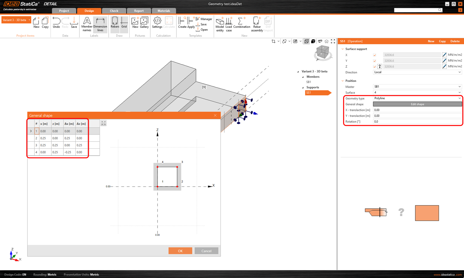
Rețineți că este posibil să specificați o polilinie astfel încât originea coordonatelor să fie la centrul de greutate al formei dorite. Poziția va fi apoi referențiată prin coordonatele X și Y față de acel centru de greutate.
Rigiditatea rezemărilor pentru fundații
În timpul modelării, putem lua în considerare două cazuri. Dacă modelăm ancorarea la structură, rezemările pot fi considerate infinit rigide.
În cazul ancorării într-un bloc de fundație, rigiditatea trebuie definită corect. În plus, rezemările trebuie definite ca numai-compresiune.
Valorile în direcția z (rigiditatea Kz) sunt preluate din literatură în funcție de tipul de teren corespunzător. Un exemplu specific poate fi găsit în tutorial.
Valorile depind de recomandările literaturii regionale relevante. Alternativ, valorile sunt obținute de la inginerul geotehnician.
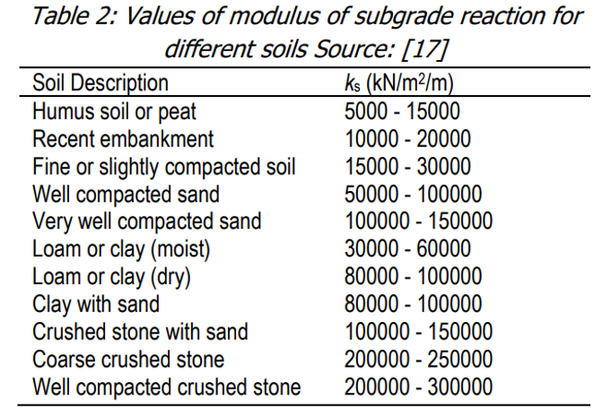
În direcțiile orizontale (Kx și Ky), situația este mai puțin simplă. Recomandarea noastră generală este să se utilizeze o valoare de aproximativ 1/10 din Kz împreună cu raționamentul ingineresc.
O abordare mai precisă ar fi utilizarea unei proceduri iterative, din care am derivat recomandarea noastră.
Mai întâi, setați Kx și Ky la valori foarte mici (din motive de calcul, nu este recomandabil să setați valoarea direct la zero), de exemplu 0,1, și examinați tensiunile din armătură.
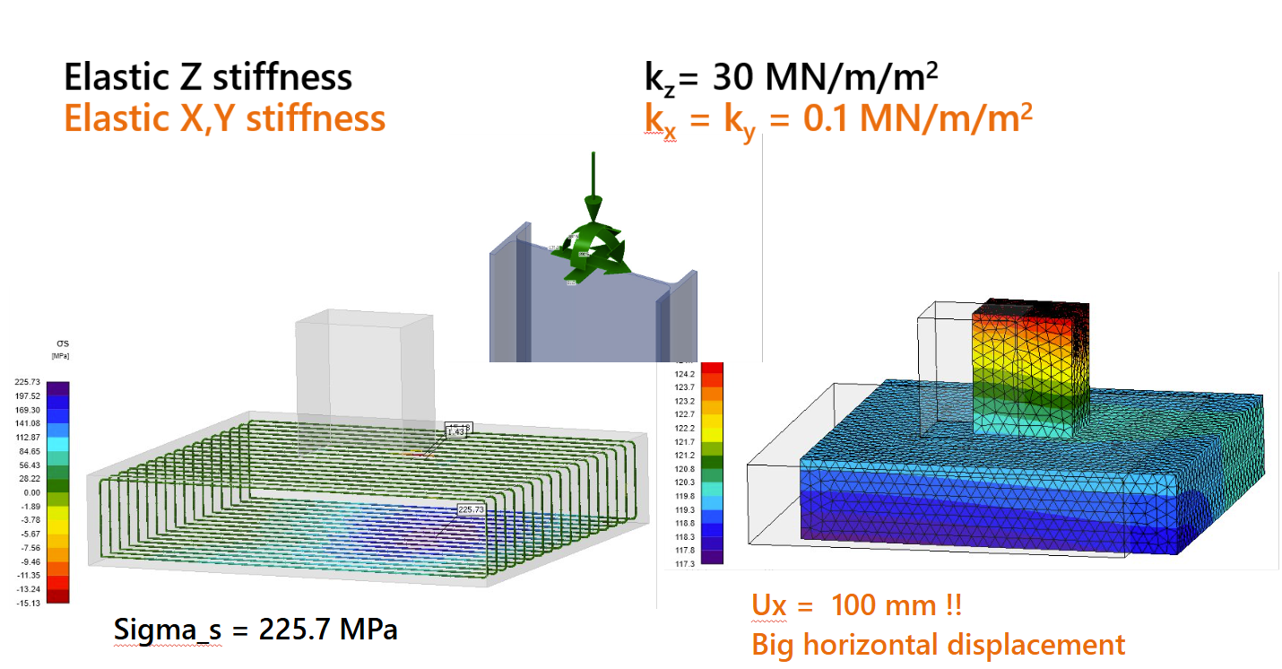
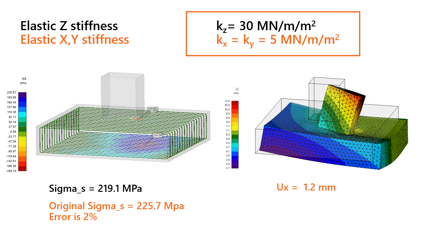
Deoarece aceste valori mici conduc la deplasări nerealiste, rigiditatea ar trebui crescută treptat pentru a reflecta mai bine realitatea. Scopul este de a obține valori de deplasare mai realiste, menținând în același timp tensiunea de întindere din armătură la marginea inferioară aproape de valoarea inițială, cu o abatere mai mică de 5%.
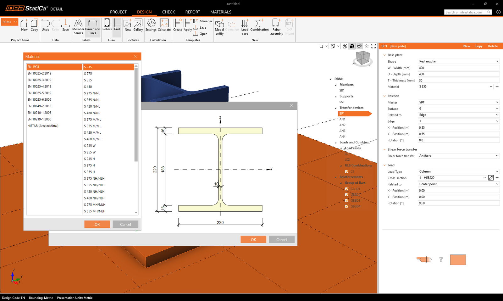
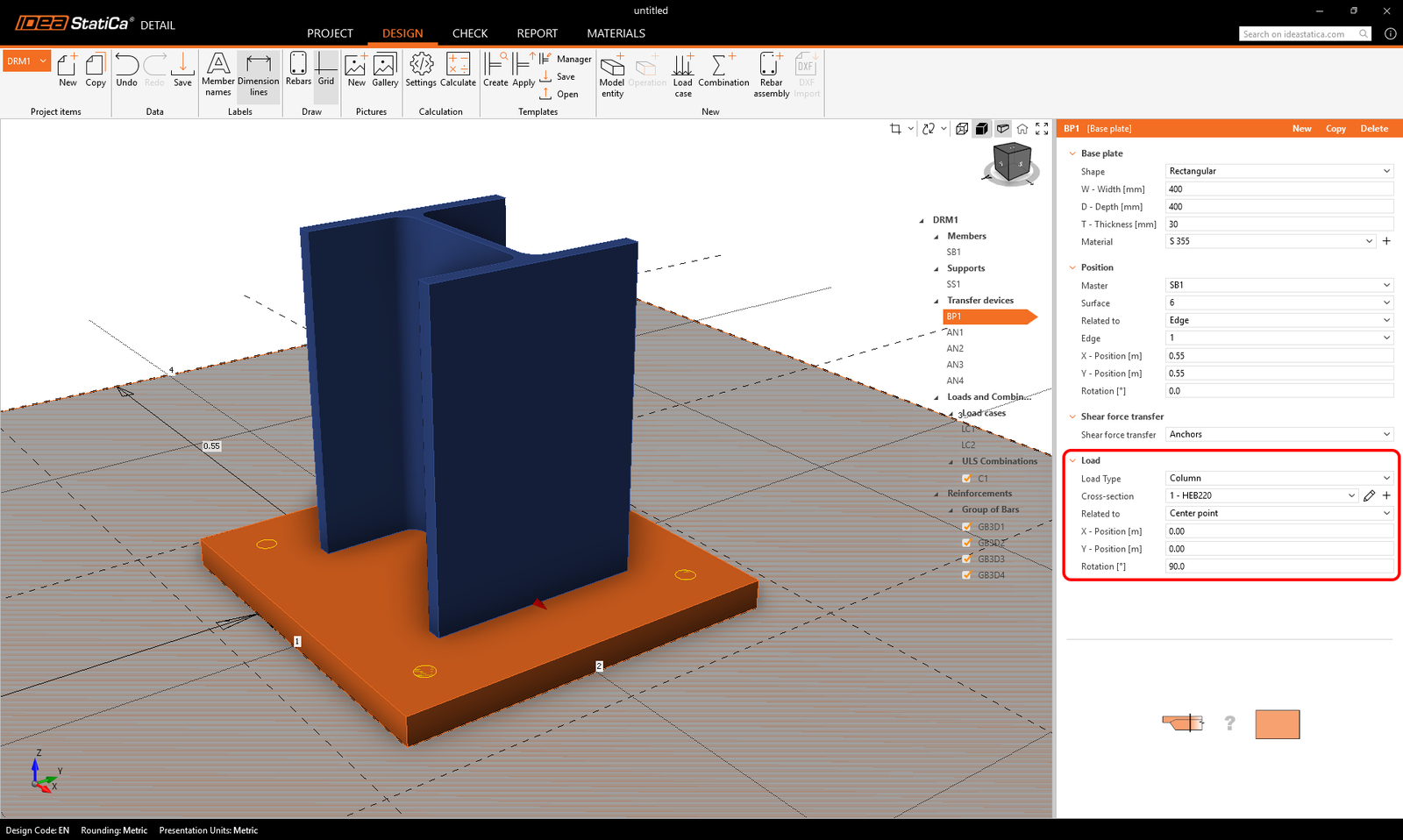
Dispozitivele de transfer al încărcărilor conțin două entități: placa de bază și ancora individuală. Să începem cu placa de bază. Pentru a specifica poziția, trebuie selectate o suprafață de referință și o muchie. Acestea definesc originea coordonatelor din care se măsoară distanțele X și Y. Există două opțiuni de definire a formei: Dreptunghiulară și Poligonală.
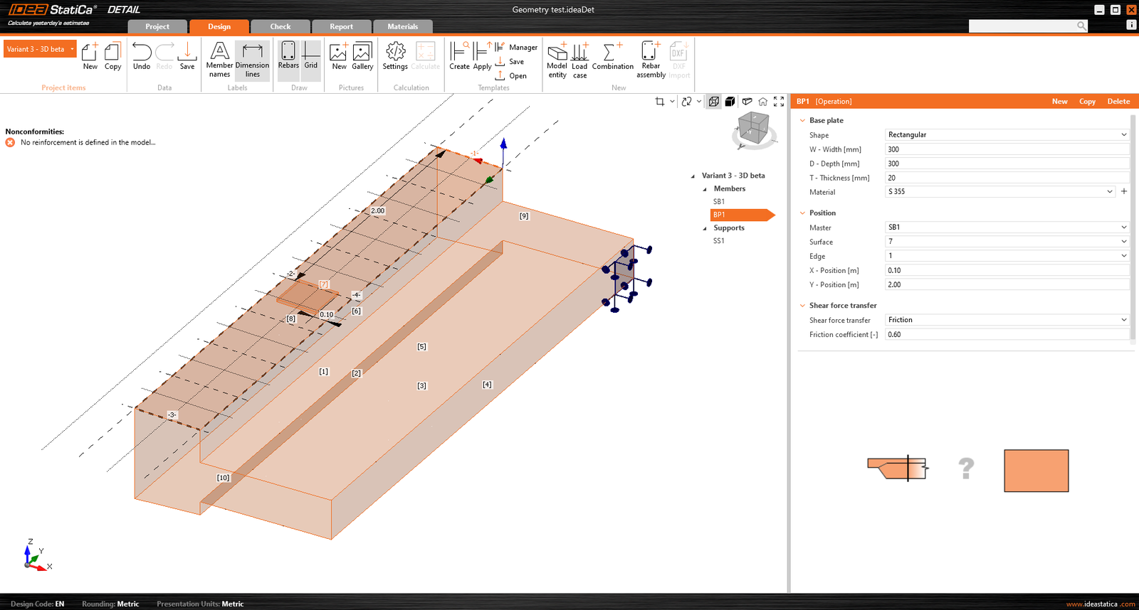
Placa de bază este conectată la elementul de beton printr-un contact care transferă tensiunile de compresiune și, dacă utilizatorul alege, poate transmite și tensiunile de forfecare. Există trei mecanisme de transfer al forțelor de forfecare care pot fi selectate:
- prin frecare
- prin ancore
- prin pivot de forfecare
Software-ul nu permite combinarea acestor mecanisme de transfer al forțelor de forfecare.
Pentru opțiunea prin frecare, trebuie introdusă valoarea de calcul a coeficientului de frecare. Pentru opțiunea prin pivot de forfecare, trebuie introdusă secțiunea de oțel, inclusiv geometria și poziția acesteia.
Toate configurațiile posibile ale plăcilor de bază pot fi găsite în articolul: Opțiuni pentru plăci de bază.
Placa de bază poate transmite fie o încărcare concentrată, fie un grup de forțe. Pentru o încărcare concentrată, modelul poate fi încărcat cu șase forțe interioare (Fx, Fy, Fz, Mx, My și Mz) în orice poziție pe placa de bază. Pentru un grup de forțe, utilizatorii pot introduce pozițiile, intensitățile și direcțiile forțelor într-un tabel, permițând o poziționare generală pe placa de bază. Este important de menționat că placa de bază este încărcată punctual și nu are niciun element de rigidizare sau element sudat pe fața sa superioară. Astfel, pentru o distribuție corectă a încărcărilor, este important să se utilizeze o placă de bază relativ rigidă, cu o grosime relativ mare. O altă opțiune este utilizarea unui Stub, care rezolvă problema rigidității plăcii.
Un al doilea dispozitiv de transfer al încărcărilor, ancora individuală, poate fi adăugat și interconectat cu placa de bază pentru a crea, de exemplu, o placă de bază a unui stâlp ancorată cu patru ancore (a se vedea figura de mai jos). Este de asemenea posibil să se modeleze ancore separate fără o placă de bază.
Mai multe informații despre interconectarea cu placa de bază pot fi găsite în Baza teoretică.
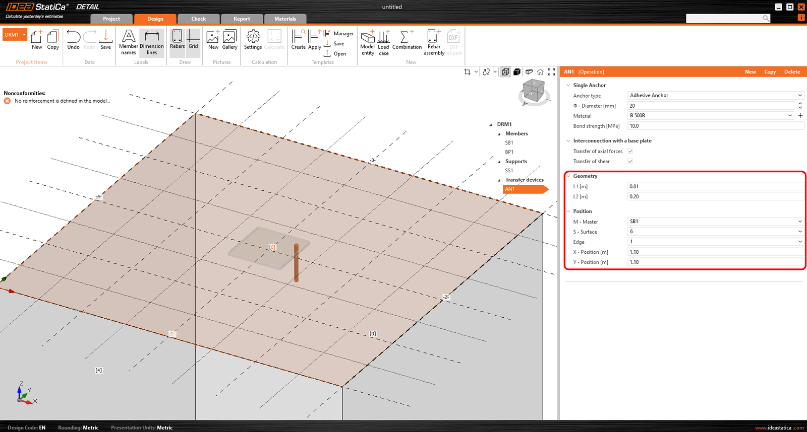
În ceea ce privește poziția și geometria, ancorele sunt referențiate față de suprafața și muchia blocului, inclusiv determinarea poziției relative, similar cu placa de bază. Desigur, este posibil să se specifice lungimea ancorei în beton și lungimea deasupra suprafeței betonului.
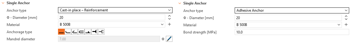
Ancorele sunt implementate în două variante:
- Turnate in situ
- Ancore adezive
Pentru armătura turnată in situ, rezistența de aderență este utilizată conform EN 1992-1-1 cap. 8.4.2. În plus, este posibil să se specifice tipul de ancoraj pentru acest tip de ancoră, similar cu armătura convențională.
Pentru ancorele adezive, este posibil să se introducă direct rezistența de aderență, pe care utilizatorul o poate găsi în fișa tehnică a mortarului adeziv aplicat. Rețineți că este necesar să se introducă valoarea de calcul a rezistenței de aderență. Următorul articol vă va ajuta să găsiți valoarea.
Consultați toate opțiunile pentru ancore în articolul: Opțiuni pentru ancora individuală
O descriere detaliată a comportamentului interconectării dintre ancoră și placa de bază este prezentată în Baza teoretică.
Încărcări
Cazurile de încărcare pot fi definite în același mod ca pentru elementele de beton armat 2D. Aceasta înseamnă că fiecărui caz de încărcare i se poate atribui fie un tip de încărcare Permanentă, fie Variabilă. Cazurile de încărcare permanentă sunt aplicate mai întâi modelului, iar după un calcul reușit, sunt aplicate cazurile de încărcare variabilă.
Tipuri de impulsuri de încărcare
Un total de 4 tipuri de impulsuri de încărcare pot fi adăugate fiecărui caz de încărcare.
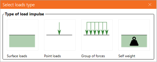
Definirea încărcărilor de suprafață este identică cu definirea rezemării de suprafață. Aceasta înseamnă că poate fi specificată în două moduri: Suprafață întreagă și Polilinie. În cazul încărcărilor de suprafață, intensitatea încărcării este introdusă, desigur, în cele trei direcții generale.
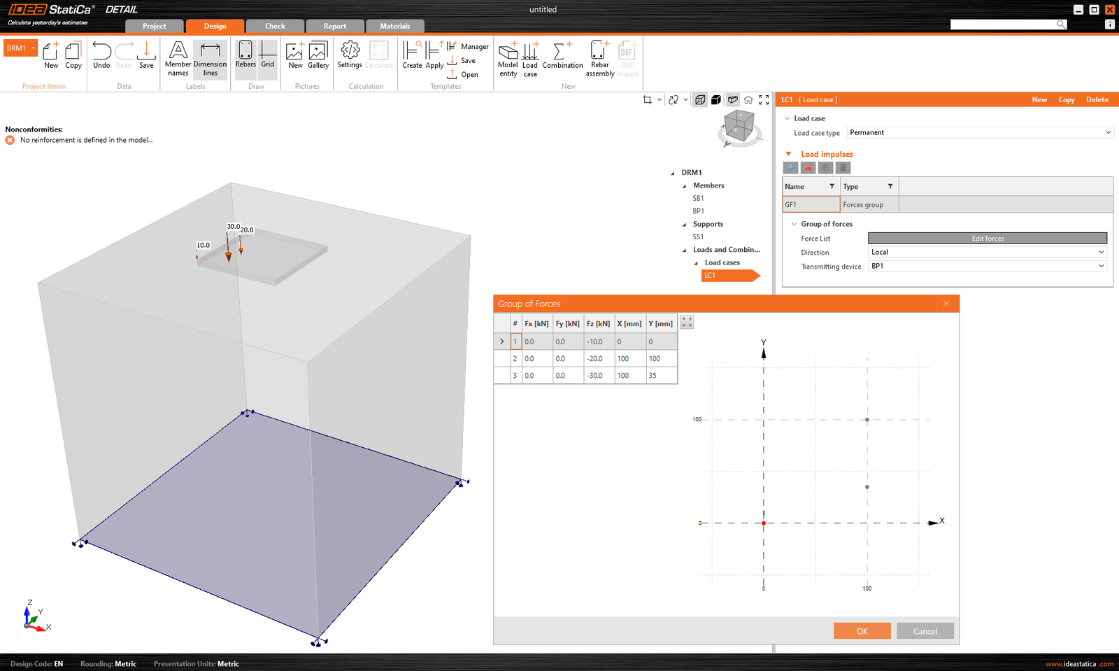
Grupul de forțe este o entitate de încărcare care permite specificarea forțelor în trei direcții în orice punct al modelului folosind un tabel. Poate fi referențiat față de placa de bază sau față de suprafața unui bloc de beton. Pentru introducerea tabelară, este posibilă din nou utilizarea funcționalității de copiere-lipire din programul de calcul tabelar.
Greutatea proprie ar trebui inclusă în fiecare model. De exemplu, fundațiile din beton încărcate cu un moment încovoietor nu se vor răsturna atât de ușor.
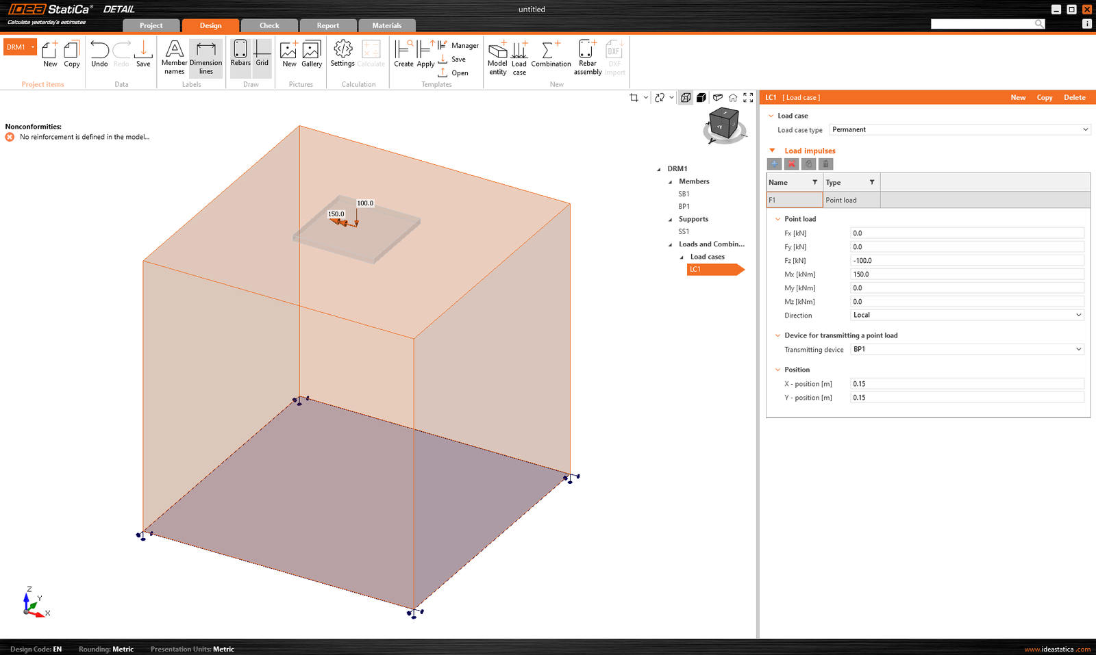
Încărcările concentrate pot fi aplicate direct pe placa de bază cu șase forțe interioare Fx, Fy, Fz, Mx, My și Mz în poziție generală.
Atunci când se utilizează o placă de bază, aplicarea acestei forțe direct pe o placă de bază realistă și deformabilă poate conduce la o redistribuire nerealistă a tensiunilor pe placă, ancore și beton. Prin urmare, este mai adecvat să se utilizeze a doua opțiune - tronsonul scurt.
Tronsonul scurt
Tronsonul scurt este reprezentat de o porțiune scurtă a stâlpului deasupra plăcii de bază, care este modelată ca o structură din elemente de tip placă și se comportă ca o interfață fizic precisă între forțele interioare și placă. Se utilizează o bază de date standard de secțiuni.
Setul de 6 componente de forțe interioare (forțe și momente) este aplicat într-un singur punct pe fața inferioară a tronsonului scurt - adică la baza stâlpului.
Constrângerile transferă forțele către fața superioară a tronsonului scurt, de unde acestea sunt în mod natural redistribuite prin tronsonul scurt în placa de bază, ancore și beton.
Această abordare păstrează interacțiunea realistă de rigiditate dintre stâlp și placă și elimină necesitatea oricărei redistribuiri manuale sau a unor ipoteze artificiale.
Tronsonul scurt a fost introdus în IDEA StatiCa versiunea 25.1.
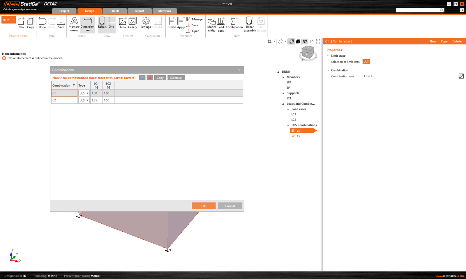
Combinații
Deoarece analiza în IDEA StatiCa Detail este neliniară, se utilizează așa-numitele combinații neliniare. Aceasta înseamnă că cazurile individuale de încărcare nu sunt calculate separat, iar rezultatele nu sunt apoi însumate. Dimpotrivă, cazurile de încărcare de același tip sunt însumate înainte de calcul, desigur cu coeficienții respectivi definiți în combinații, iar combinațiile individuale sunt apoi calculate. De aceea, existența cel puțin a unei combinații este o condiție prealabilă pentru inițierea calculului.
Pot fi definite numai combinații pentru SLU.
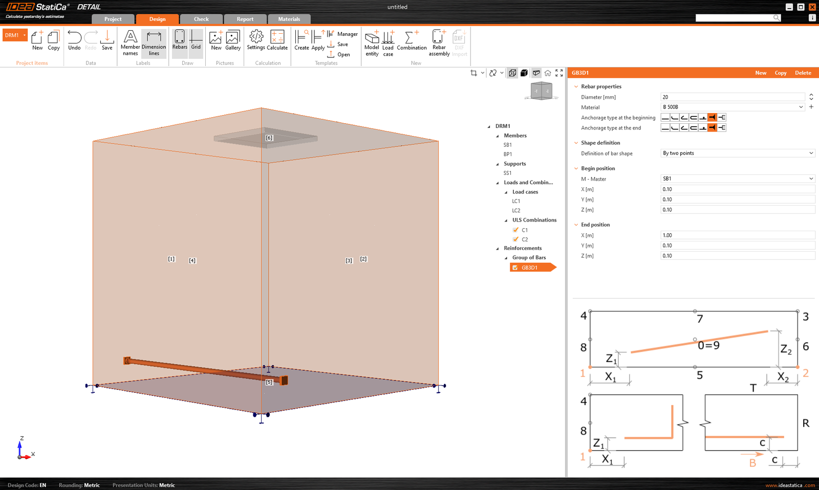
Modelul poate fi armat cu Grup de bare 3D. Acest tip de armătură conține multe opțiuni, pe care le vom parcurge în textul următor. Astfel, pot fi specificate 4 tipuri de Definiții ale formei barei:
- Prin două puncte
- Pe muchia suprafeței
- Pe muchia suprafeței pe mai multe muchii
- Pe polilinie
Pentru fiecare dintre aceste elemente puteți, desigur, specifica diametrul și materialul, inclusiv tipul de ancoraj la începutul și la sfârșitul barelor.
Definiția formei barei Prin două puncte este explicită. Trebuie să introduceți două seturi de coordonate carteziene X, Y, Z.
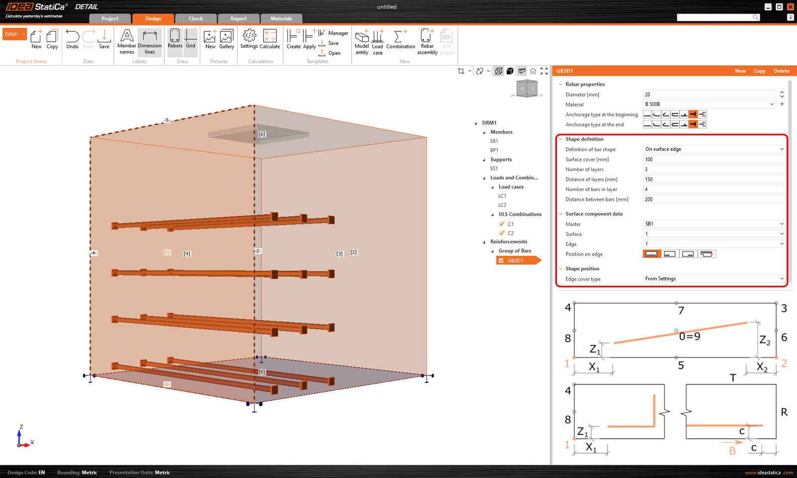
Definiția Pe muchia suprafeței oferă numeroase opțiuni de control pentru poziționarea barelor de armătură în locația dorită. Puteți introduce bare de armătură în mai multe straturi, cu mai multe bare într-un strat, cu distanțe specificate între bare și între straturi. Desigur, este necesar să specificați și suprafața de referință și muchia. În continuare, trebuie să specificați Acoperirea suprafeței, care definește distanța față de suprafața de referință (față de suprafața [1] din figura de mai jos), și Acoperirea muchiei, care definește distanța inserțiilor față de suprafețele laterale (față de suprafețele [4], [5] și [2] din figura de mai jos); aceasta poate fi specificată ca Din setări sau Introducere utilizator. Valoarea implicită a acoperirii (Din setări) pentru elementul de Proiect activ poate fi găsită în primul element al arborelui (denumit implicit DRM1). Aceasta a fost definită la începutul acestui articol. Acoperirea muchiei poate fi setată ca valoare unică pentru fiecare Grup de bare.
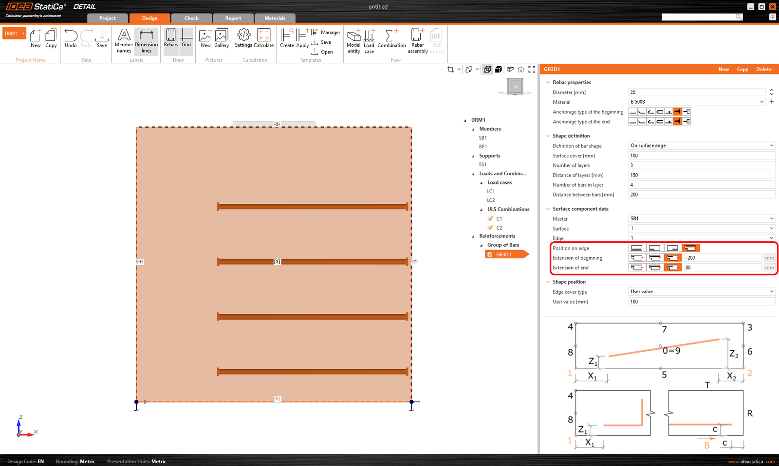
În cele din urmă, Poziția pe muchie poate fi editată pentru acest tip de introducere. De exemplu, după cum se arată în figura de mai jos, este posibil să specificați armătura astfel încât Acoperirea muchiei definită de utilizator să fie aplicată doar suprafeței inferioare [5]. Suprafețele laterale sunt controlate de Extensia de la început și de la sfârșit.
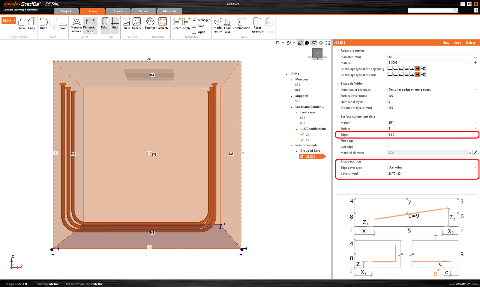
Un alt tip de definiție este Pe muchia suprafeței pe mai multe muchii. Aici este posibil să specificați o listă de muchii sau suprafețe pe care va fi plasată armătura, împreună cu o listă de straturi de acoperire pentru fiecare suprafață, după cum se arată în figura următoare.
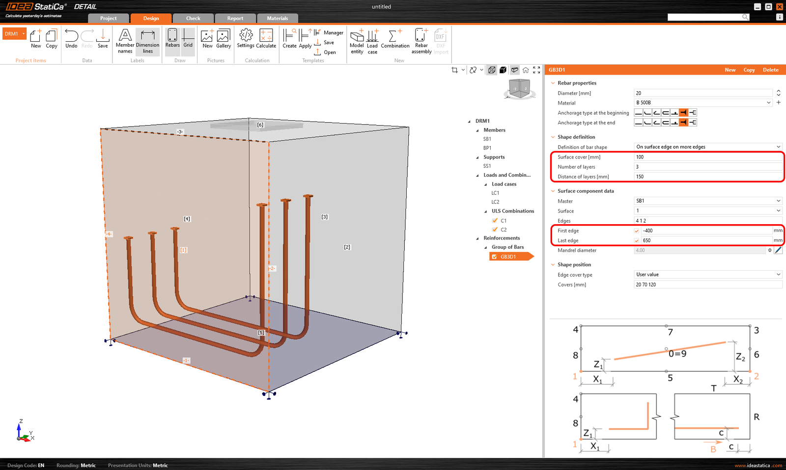
Acoperirea poate fi specificată și folosind opțiunea Din setări, ca și în cazul precedent. De asemenea, este posibil să decalați armătura față de suprafața de referință folosind Acoperirea suprafeței și să specificați Numărul și Distanța straturilor. Este posibil, de asemenea, să prelungiți sau să scurtați capetele de la Prima muchie și Ultima muchie.
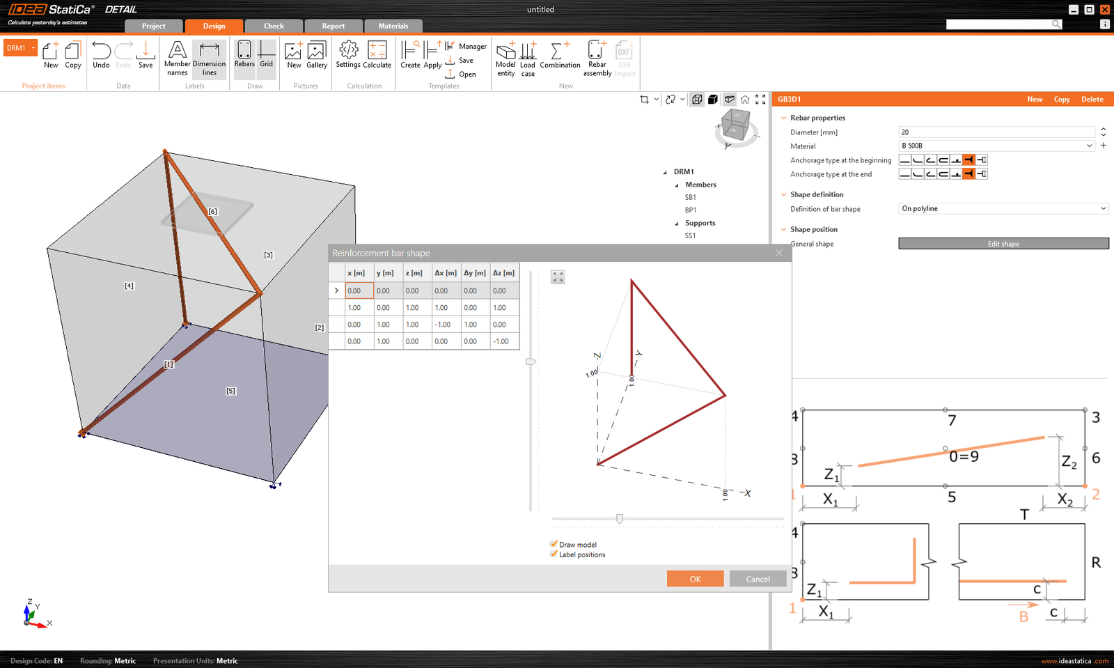
Ultima modalitate de definire a armăturii este Pe polilinie. Ca și în cazul entităților de model menționate mai sus, armătura poate fi specificată folosind o listă de coordonate copiate dintr-un program de calcul tabelar. În acest caz, este disponibilă suplimentar o scenă 3D cu armătura afișată pentru o orientare mai bună, permițând rotații în jurul a două axe.
Ancorarea într-un bloc de beton simplu poate fi modelată și verificată conform codului în IDEA StatiCa Connection. În anumite cazuri, cum ar fi ancorarea în apropierea marginii, proiectarea este insuficientă din cauza modurilor posibile de cedare, iar armătura suplimentară este necesară. Deși această funcționalitate nu este disponibilă în aplicația Connection, este posibil să se continue direct în aplicația Detail.
Detail 3D este orientat spre rezolvarea ancorării în blocuri de beton și analiza atât a elementelor de ancorare, cât și a blocului de beton în sine. Mai mult, o legătură directă este implementată între aplicațiile Connection și Detail pentru a simplifica procesul. Utilizatorii Connection care proiectează ancorarea conform Eurocode sau AISC pot importa modelul din Connection în Detail 3D avansat printr-un singur clic pe buton.
- Importul este permis doar pentru ancorare. Dacă nu există niciun bloc de beton în modelul Connection, exportul în Detail este dezactivat („RC check").
- Modelul în Connection trebuie să fie calculat. Dacă rezultatele nu sunt disponibile, pictograma de export („RC check") este dezactivată. Pentru funcționalitatea de export, este de asemenea necesar să aveți licențe valide pentru aplicațiile de beton. În caz contrar, opțiunea de export va fi din nou dezactivată.
- Este permis un singur bloc de beton pentru import/export.
- Unele tipuri de ancore nu sunt acceptate pentru import și, de asemenea, nu recomandăm exportul așa-numitei ancorări de margine. O prezentare detaliată a limitărilor este furnizată în articol: Limitări cunoscute pentru Detail 3D
Îmbinarea este importată, inclusiv
- Blocul de beton
- Ancorele
- Plăcile de bază
- Încărcările
Informații suplimentare și parametri care sunt setați conform setărilor corespunzătoare din Connection:
- Transferul forței tăietoare (prin Ancore, Pivoți de forfecare și Frecare)
- Material
- Tipul de ancoraj
- Tipul de ancoraj la capăt
- Coeficientul de frecare
Configurațiile posibile și tipurile de ancore care pot fi exportate pot fi găsite în următoarele articole:
Export din Connection în Detail pas cu pas
Mai întâi, creați un model de ancorare în Connection conform Eurocode/AISC și faceți clic pe butonul Calculați.
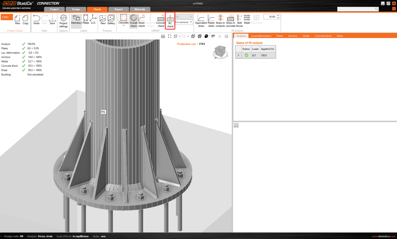
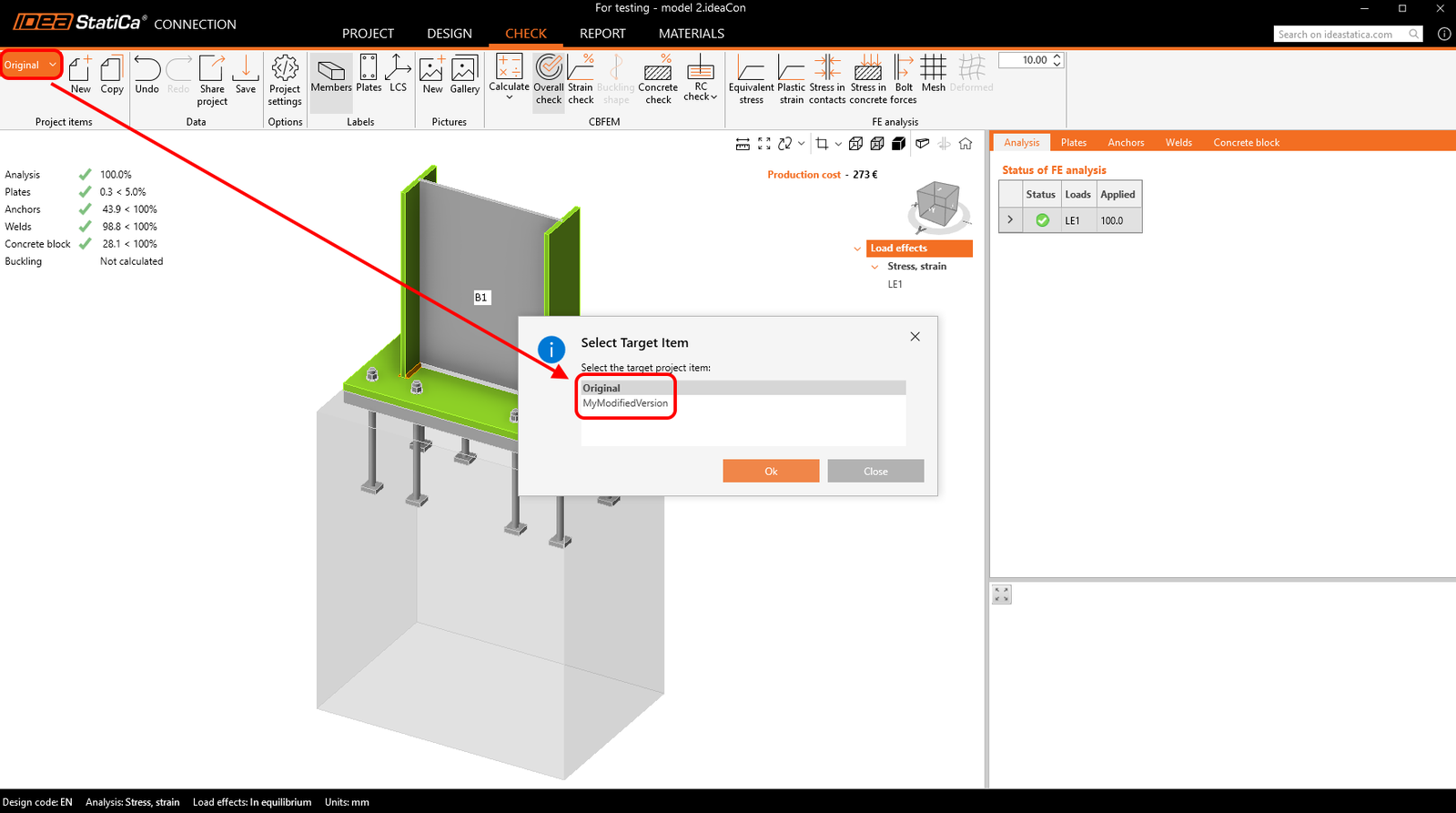
Când există rezultate, exportul fundației este activat. Făcând clic pe butonul „RC Check" din panglică, apare un dialog care solicită locația și numele noului fișier Detail creat.
După un export reușit, proiectul în Detail este creat. Geometria blocului de beton și a plăcii de bază, poziția și proprietățile ancorelor, precum și încărcarea sunt transferate automat în Detail. Rezemarea de suprafață plasată pe suprafața inferioară a blocului de beton este creată automat.
Notă: Este necesar doar să verificați setările în direcția Z. (Pentru fundații, folosim numai compresiune cu setarea rigidității terenului; pentru o structură continuă, putem activa și rezemarea la întindere).
Cea mai dificilă parte a acestui proces este importul încărcării. Pentru fiecare încărcare calculată în Connection, cazul de încărcare corespunzător și combinația SLU sunt create automat în Detail.
- Placa de bază este încărcată prin forțe în suduri, care sunt modelate ca un Grup de forțe. Pentru încărcarea plăcii de bază în sine, încărcarea importată este reprezentată printr-un grup de forțe care urmează tensiunile în sudurile dintre placa de bază și elementele metalice din modelul Connection.
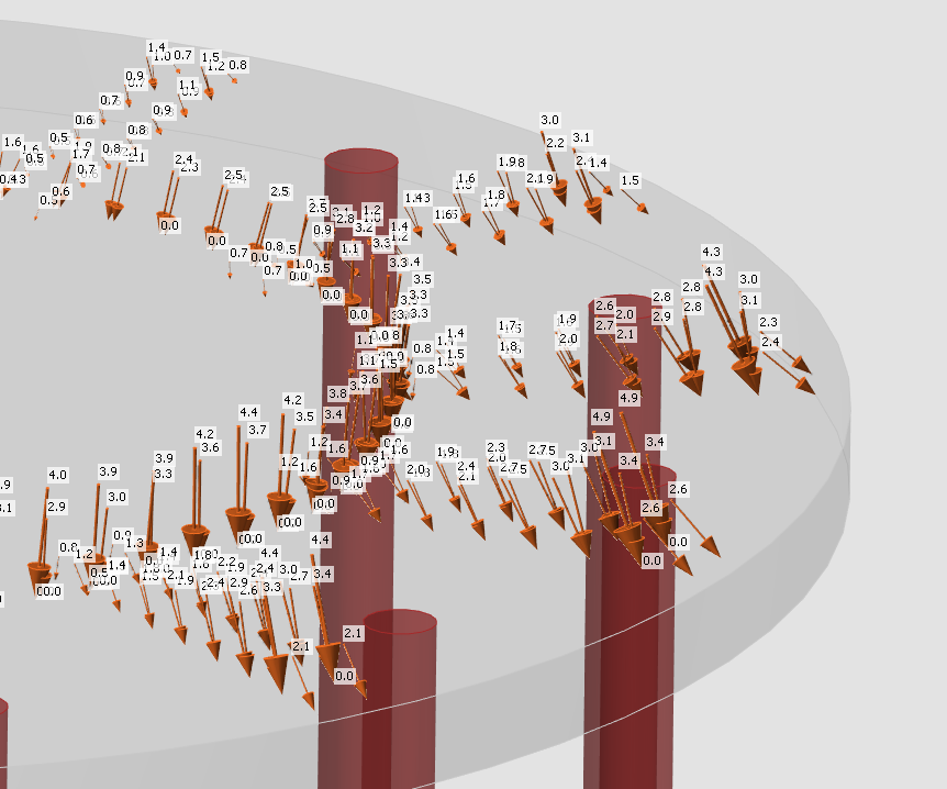
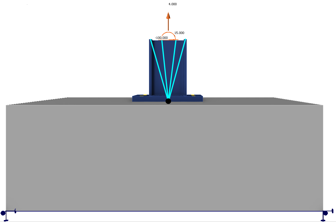
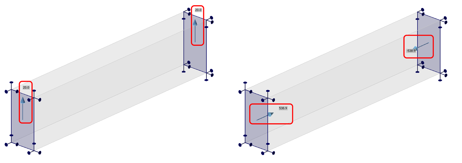
- Ancorele sunt modelate și încărcate independent de placa de bază și sunt încărcate axial prin forțe concentrate. Încărcarea ancorelor este reprezentată în scenă printr-o pereche de săgeți în direcții opuse. O săgeată reprezintă forța de întindere acționând doar pe partea superioară a ancorei. Cealaltă reprezintă forța de compresiune acționând pe placa de bază.
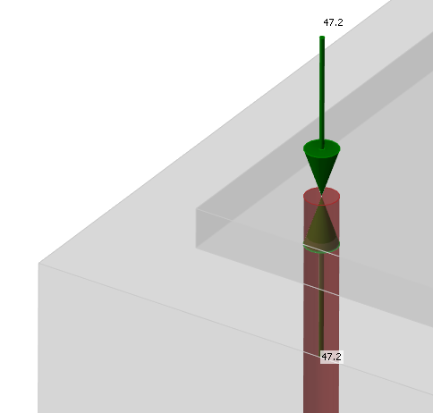
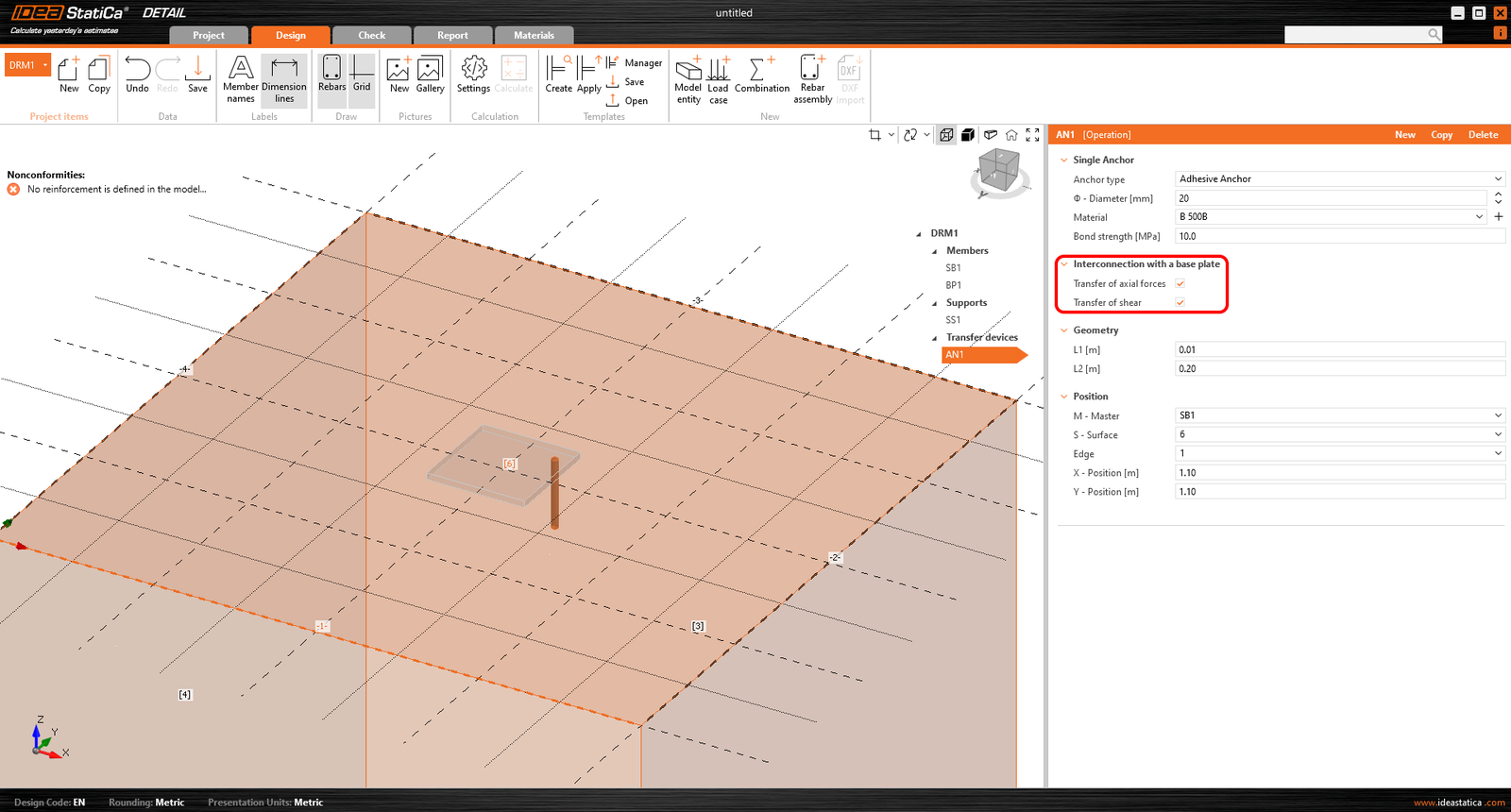
Caseta de selectare „Transferul forțelor axiale" este debifată implicit, deoarece ancorele sunt încărcate direct prin forțe.
Notă: Figura următoare nu se aplică plăcilor turnate in situ, unde transferul forței axiale este verificat corect după export. Motivul pentru aceasta poate fi găsit în Baza Teoretică.
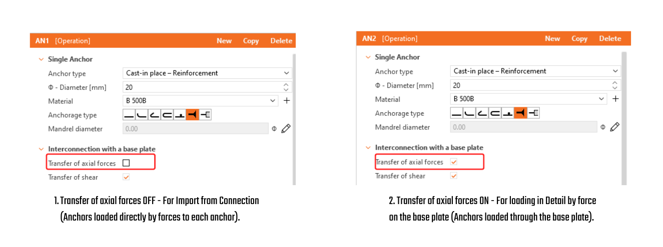
- Forța tăietoare este transferată conform setării din Connection prin una dintre opțiuni – ancore, pivoți de forfecare sau frecare. Dacă forța tăietoare este transferată prin ancore, puteți dezactiva ancore specifice debifând caseta de selectare „Transferul forței tăietoare".
- Dacă sunt setate frecarea sau pivoții de forfecare, forța tăietoare în ancore nu este niciodată luată în considerare în model. (Chiar dacă caseta de selectare este bifată.)
Apoi, adăugați armătura necesară folosind instrumentele menționate mai sus și calculați modelul. Nu uitați să setați Rezistența de aderență de calcul pentru ancorele adezive (post-instalate) conform parametrilor producătorului.
De asemenea, este recomandat să verificați că încărcarea specificată nu va răsturna blocul de beton. Răsturnarea poate fi prevenită prin greutatea proprie sau o forță normală de compresiune suficientă. Dacă forța verticală rezultantă este pozitivă (blocul va fi ridicat de pe reazem), calculul va eșua de asemenea.
Deoarece betonul nu acționează la întindere, acoperirea dintre armătura inferioară și reazem va fi desprinsă.
O explicație detaliată a forțelor importate care acționează pe placa de bază sau pe ancore, prezentate în figura de mai jos, poate fi găsită în Baza teoretică.
Sincronizare unidirecțională din Connection în Detail
Aplicația Connection oferă o funcție „Actualizare existentă" pentru a sincroniza un proiect Detail cu cele mai recente date din Connection, eliminând necesitatea de a recrea modelul de la zero.
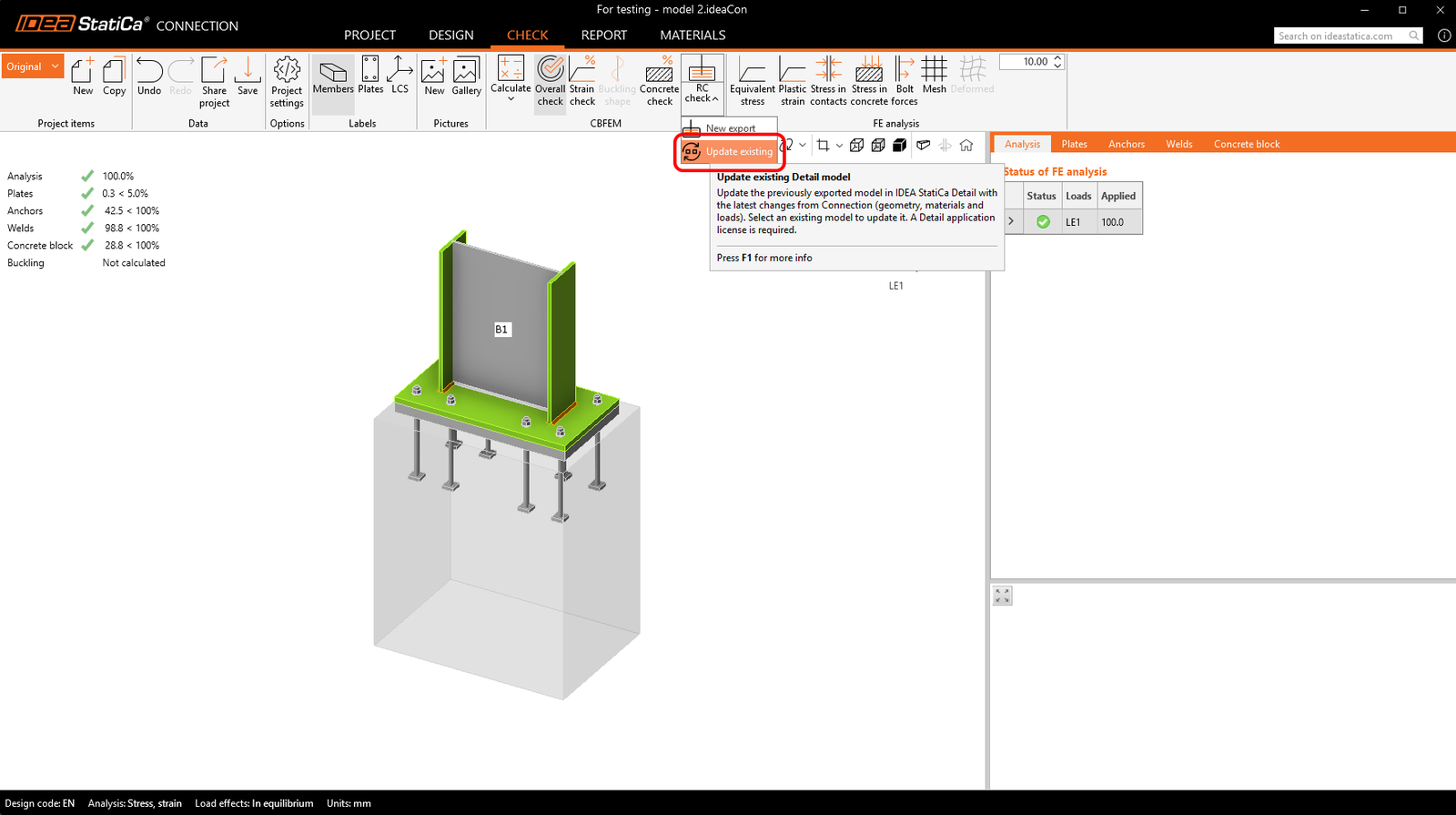
Procesul de actualizare sincronizează următoarele date:
- Bloc de beton: geometrie și material
- Placă de bază / placă turnată in situ: geometrie și material
- Ancore / dispozitive de fixare: geometrie și material
- Date de încărcare: cazuri de încărcare, impulsuri și combinații
Setările nu sunt importate/sincronizate, deci codul trebuie setat întotdeauna corect.
În timpul actualizării, entitățile create inițial din Connection sunt gestionate după cum urmează: entitățile existente sunt actualizate cu noile date, entitățile care nu mai sunt prezente în Connection sunt șterse, iar noile entități din Connection sunt adăugate la proiectul Detail. Entitățile create direct în Detail rămân nemodificate, inclusiv volumele negative, tăierile, operațiile booleene, armătura, plăcile, ancorele și cazurile de încărcare.
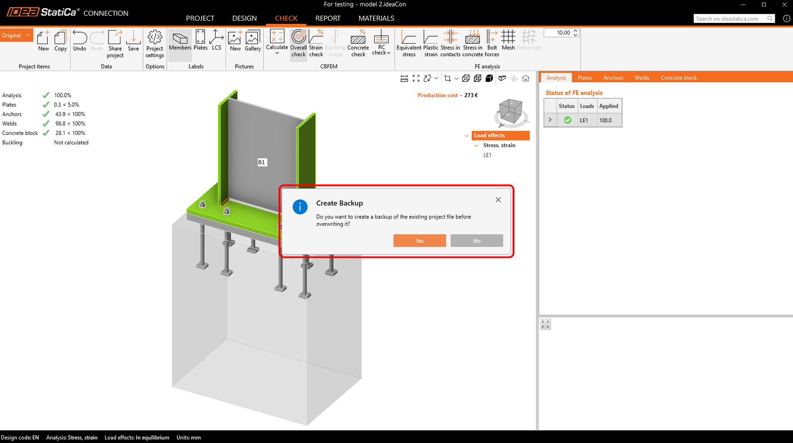
Înainte de actualizare, sistemul solicită crearea unei copii de rezervă, iar copiile de rezervă sunt stocate automat în același folder pentru a asigura recuperarea stării anterioare.
Fluxul de lucru acceptă mai multe elemente de proiect atât în Connection, cât și în Detail. Este posibil să copiați un element de proiect Connection pentru a crea o variantă și apoi să o sincronizați cu proiectul Detail corespunzător. Actualizările sunt acceptate și pentru proiectele Detail care conțin mai multe elemente de proiect, permițând ca toate datele relevante să rămână consistente.
Notă: Lansat în IDEA StatiCa versiunea 24.1. pentru EN. Îmbunătățit treptat prin implementarea AISC, adăugarea opțiunilor pentru elementele de ancorare și rafinarea limitărilor. Acest articol, inclusiv funcționalitatea completă, este aplicabil începând cu versiunea 26.0. Modificările individuale pot fi văzute în notele de lansare.
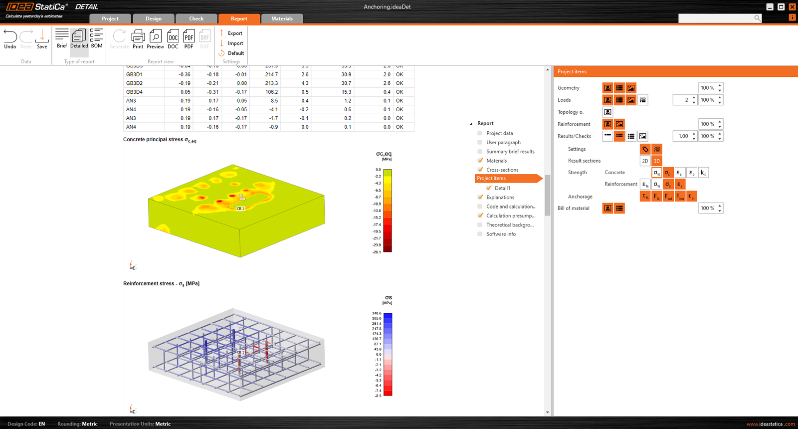
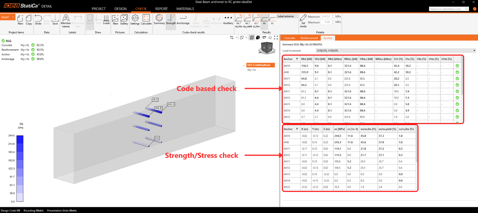
Afișarea rezultatelor este foarte similară cu cea din Detail 2D. Cu toate acestea, există câteva diferențe majore, în special în ceea ce privește rezultatele pentru beton și rezultatele ancorelor. În secțiunea următoare, vom parcurge toate rezultatele disponibile, concentrându-ne pe diferențele menționate. În fila de verificare puteți vizualiza un total de 4 tipuri de rezultate:
- Sumar
- Verificarea rezistenței și a ancorelor conform codurilor
- Ancorajul armăturii
- Alte rezultate suplimentare
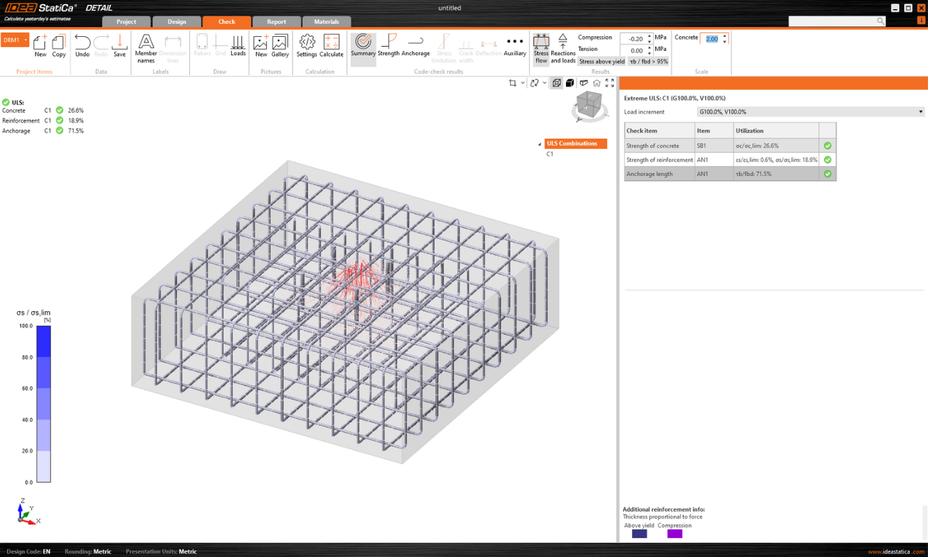
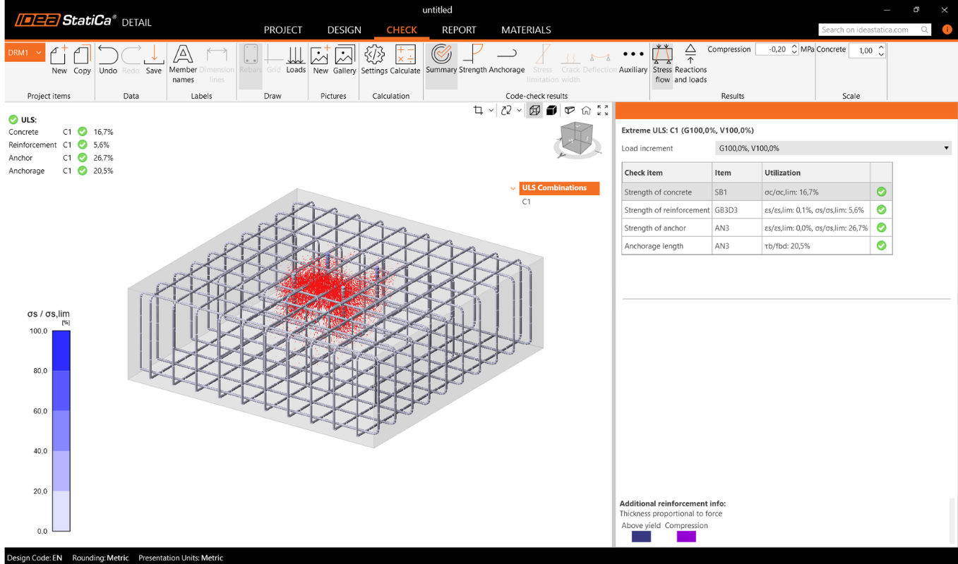
Fluxul de tensiuni în rezultatele Sumar vă arată vectorii tensiunilor principale de compresiune în beton și gradul de utilizare al armăturii și ancorelor, pentru a vă oferi o imagine de ansamblu de bază.
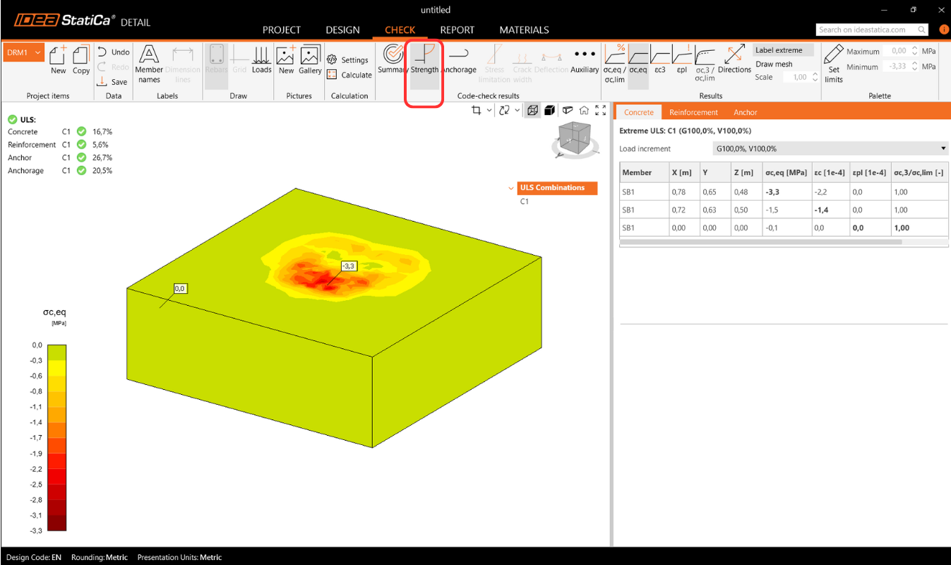
Verificarea rezistenței betonului, armăturii și ancorelor
În verificarea Rezistenței puteți afișa redistribuția tensiunilor și deformațiilor pentru beton. În bara de instrumente superioară din bara de instrumente Rezultate, puteți controla ce va fi afișat. Este posibil, de asemenea, să afișați rapoartele σc,eq/σlim, și ε/εlim precum și deformația plastică, nivelul de triaxialitate σc3/σlim, și direcția tensiunii principale pentru beton. Toate rezultatele din Rezistență sunt legate de Starea Limită Ultimă.
Notă: Este posibil să observați că tensiunea principală echivalentă σc,eq este zero imediat sub placa de bază comprimată. Vă rugăm să citiți Fundamentele teoretice unde σc,eq este definită. Sau puteți parcurge acest articol de verificare, unde acest fenomen este explicat și verificat folosind un test triaxial bine cunoscut: Tensiune triaxială – efectul de confinare activă
Materialele pot fi schimbate în proprietăți.
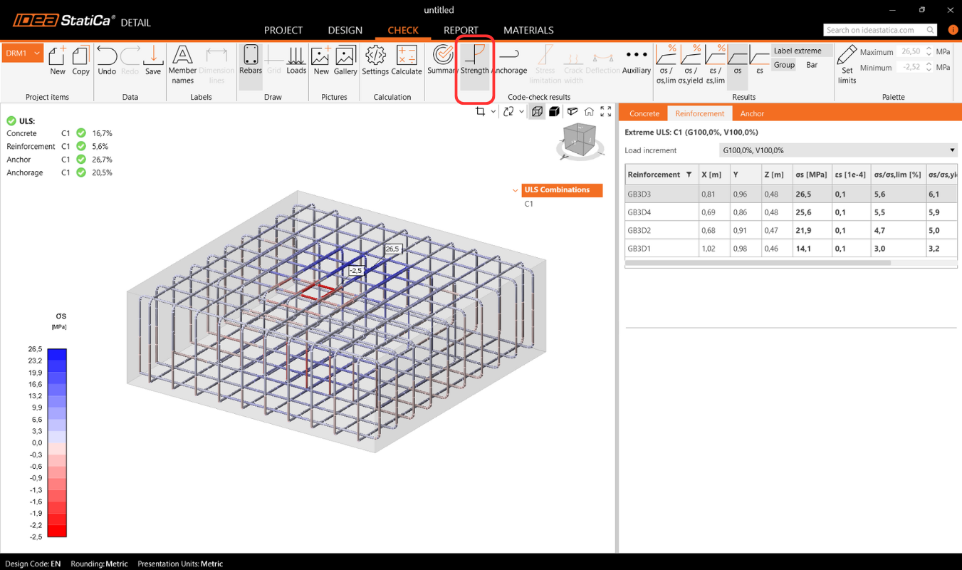
Verificarea pentru armătură se efectuează într-un mod foarte similar, unde comparăm din nou valorile limită cu tensiunea/deformația calculată - σs/σlim, și εs/εlim.
Pentru ancore, avem două verificări. Una este la fel ca pentru armătură — comparând valorile limită - σs/σlim, și εs/εlim.
Notă: Este posibil să observați că fiecare ancoră este verificată în mai multe poziții, care sunt calculate automat ca și cazuri extreme.
Verificarea conform codului a ancorelor conform codului de proiectare
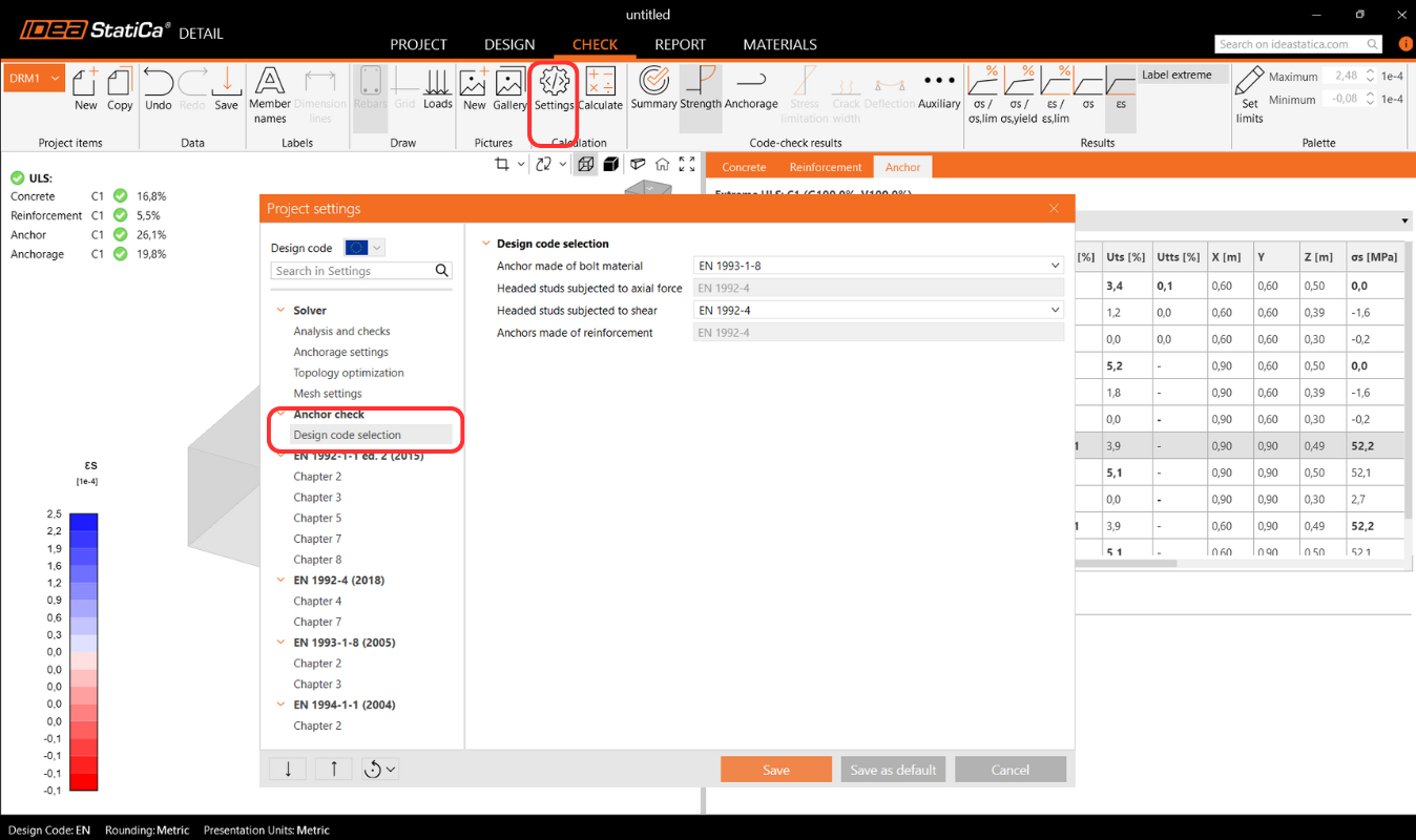
În plus, avem verificări bazate pe codul de proiectare (EN, ACI/AISC, AUS), care sunt efectuate empiric conform standardului. Standardul specific luat în considerare poate fi văzut în setări, unde este posibil, de asemenea, să selectați unul diferit în funcție de tipul de ancorare utilizat (placă de bază în contact direct cu betonul, placă de bază cu mortar de nivelare și placă de bază cu rost), precum și standardul necesar bazat pe practicile regionale.
Coduri implementate: EN 1992-4, EN 1993-1-8, EN 1994-1-1, ACI318-19, AISC 360-16, AS3600, AS 5216, AS 4100
Setările standardului pot fi modificate în Setările Proiectului, unde capitolele vor apărea conform standardului selectat la crearea proiectului. La importul din Connection, se recomandă verificarea că același standard este setat.
În capitolul Fundamente Teoretice - Verificări la Starea Limită Ultimă, fiecare verificare este explicată în detaliu, inclusiv toate formulele utilizate.
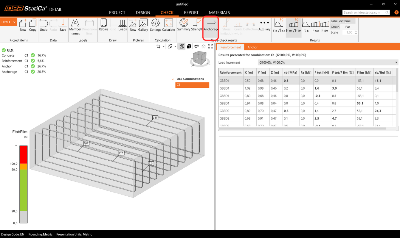
Ancorajul armăturii
Verificarea Ancorajului vă oferă informații despre tensiunea de aderență și forța totală pe armătură și ancore.
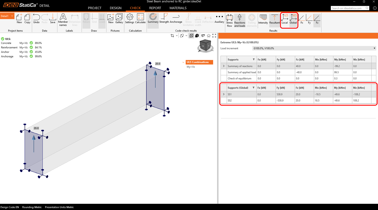
Reacțiuni de suprafață
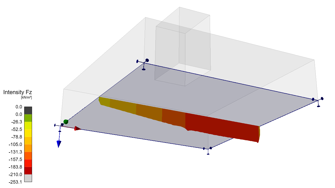
Secțiunea Reacțiuni și Încărcări include o opțiune de afișare a reacțiunilor de suprafață. Reacțiunile pot fi vizualizate în două moduri:
- Intensitate – Reacțiunile de suprafață sunt afișate pe fața rezemată a blocului de beton folosind isobande pentru a ilustra distribuția pe suprafața de rezemare.
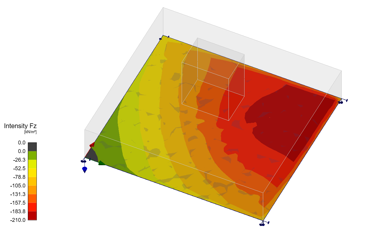
- Rezultantă – Reacțiunea rezultantă pentru fiecare reazem este afișată ca o săgeată la centrul de greutate al rezemului, indicând mărimea și direcția.
Pentru ambele moduri, reacțiunile pot fi afișate fie în Sistemul de Coordonate Global (GCS), fie în Sistemul de Coordonate Local (LCS) al rezemului.
Un nou tabel în Grila de Proprietăți listează reacțiunile sumarizate pentru reazemele individuale, disponibile și în coordonate globale sau locale.
În plus, distribuția reacțiunilor poate fi vizualizată în secțiunile transversale create de utilizator.
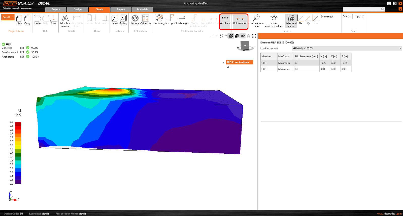
Rezultate avansate suplimentare
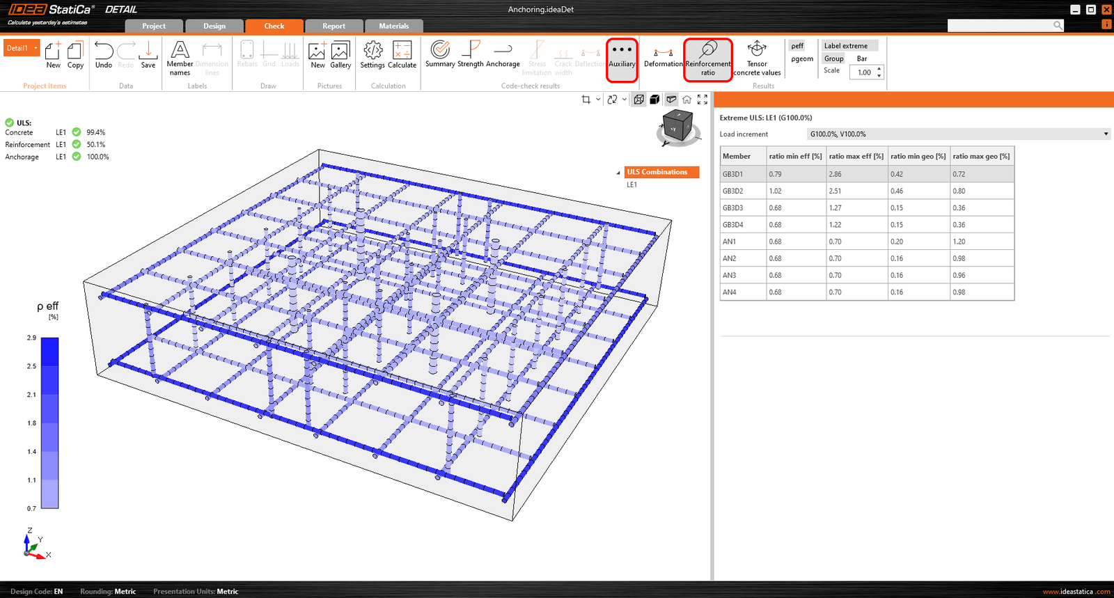
Nu în ultimul rând, puteți vizualiza rezultatele Auxiliare în aplicație - Deformație, Raport de armare și Valori tensor beton. Primul tip, Deformația, poate afișa deformațiile scalate ale modelului neliniar SLU.
Raportul de armare arată valorile utilizate pentru calculul efectului de participarea betonului întins.
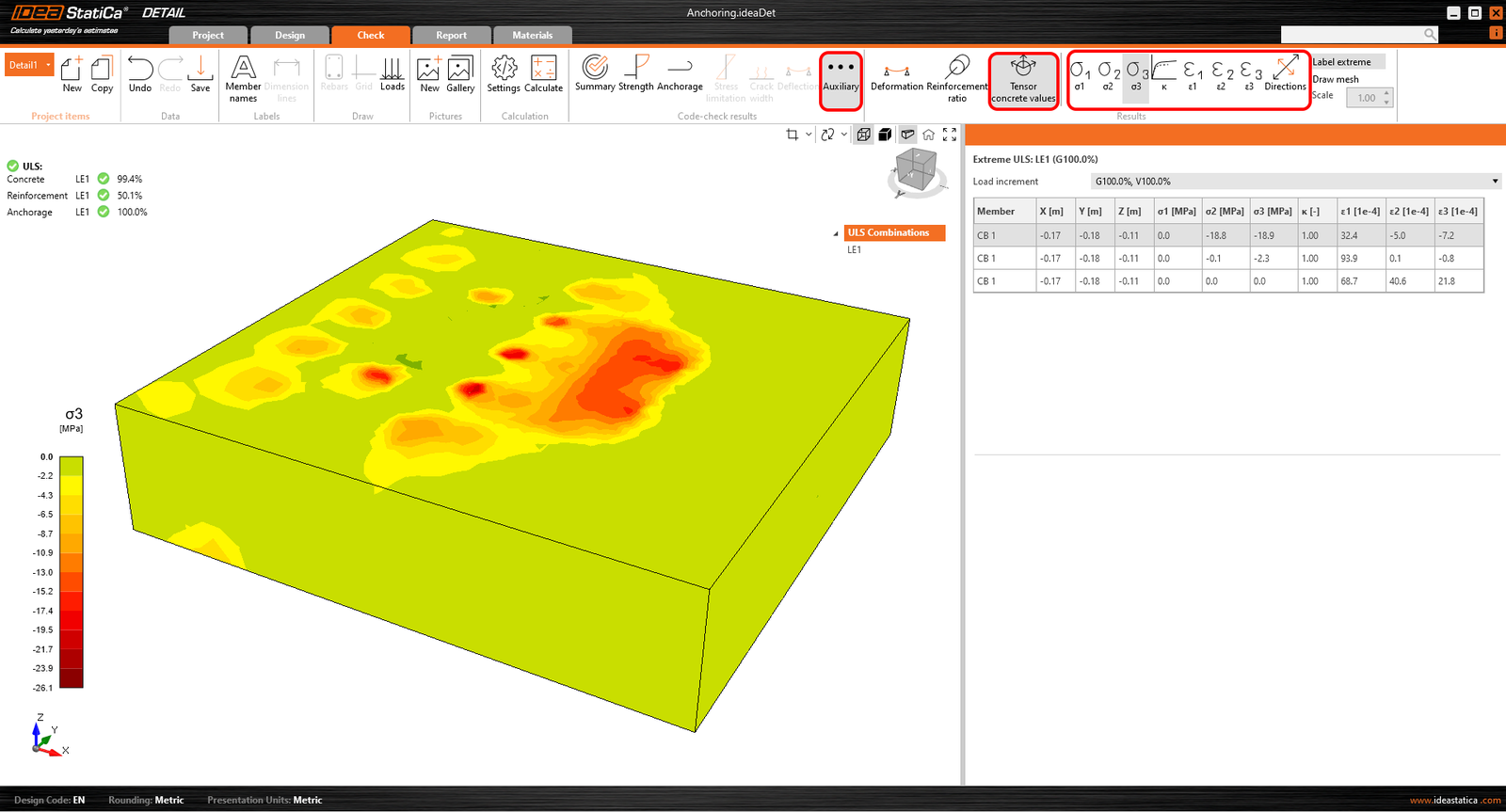
Valorile tensor beton vă permit să afișați intensitățile tensiunilor principale în beton și direcția acestora.
Secțiunile de rezultate pot fi, de asemenea, utilizate.
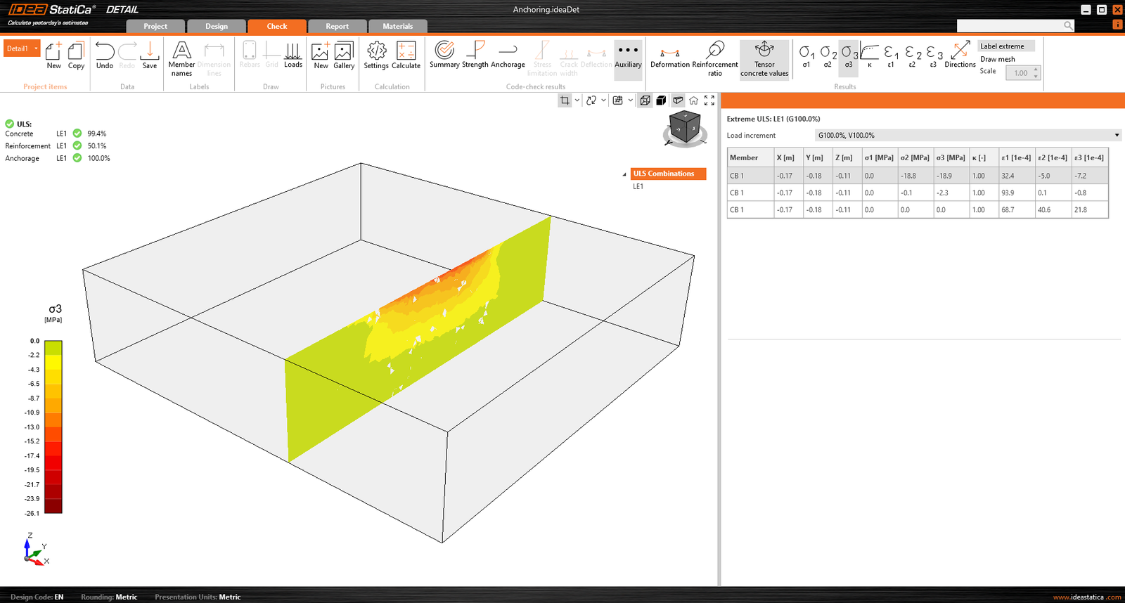
Rezultatele Section permit vizualizarea tensiunilor din elementul de beton. Este posibilă crearea oricărui număr de secțiuni și în orice plan.
Pentru modelele 3D, există o opțiune de afișare a rezultatelor pentru beton - Section results. Pentru a defini sau modifica secțiunile, trebuie să utilizați butonul de secțiune din controlul vederii, care se află în colțul din dreapta sus al scenei.
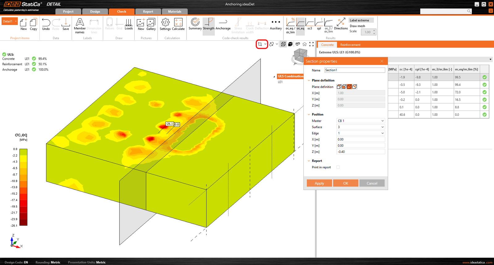
Apoi puteți activa pur și simplu butonul de secțiune, iar rezultatele vor fi afișate printr-o secțiune specificată.
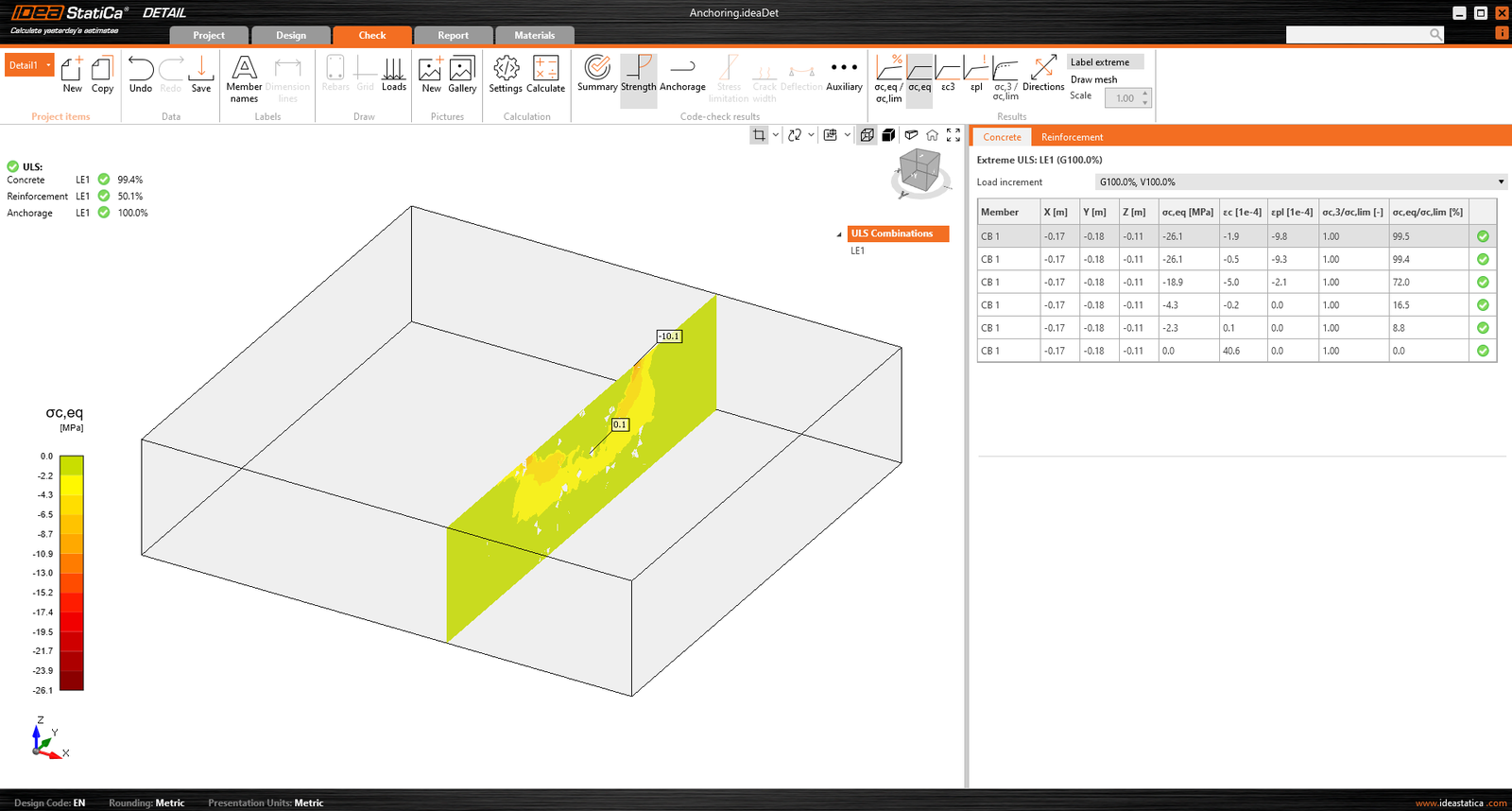
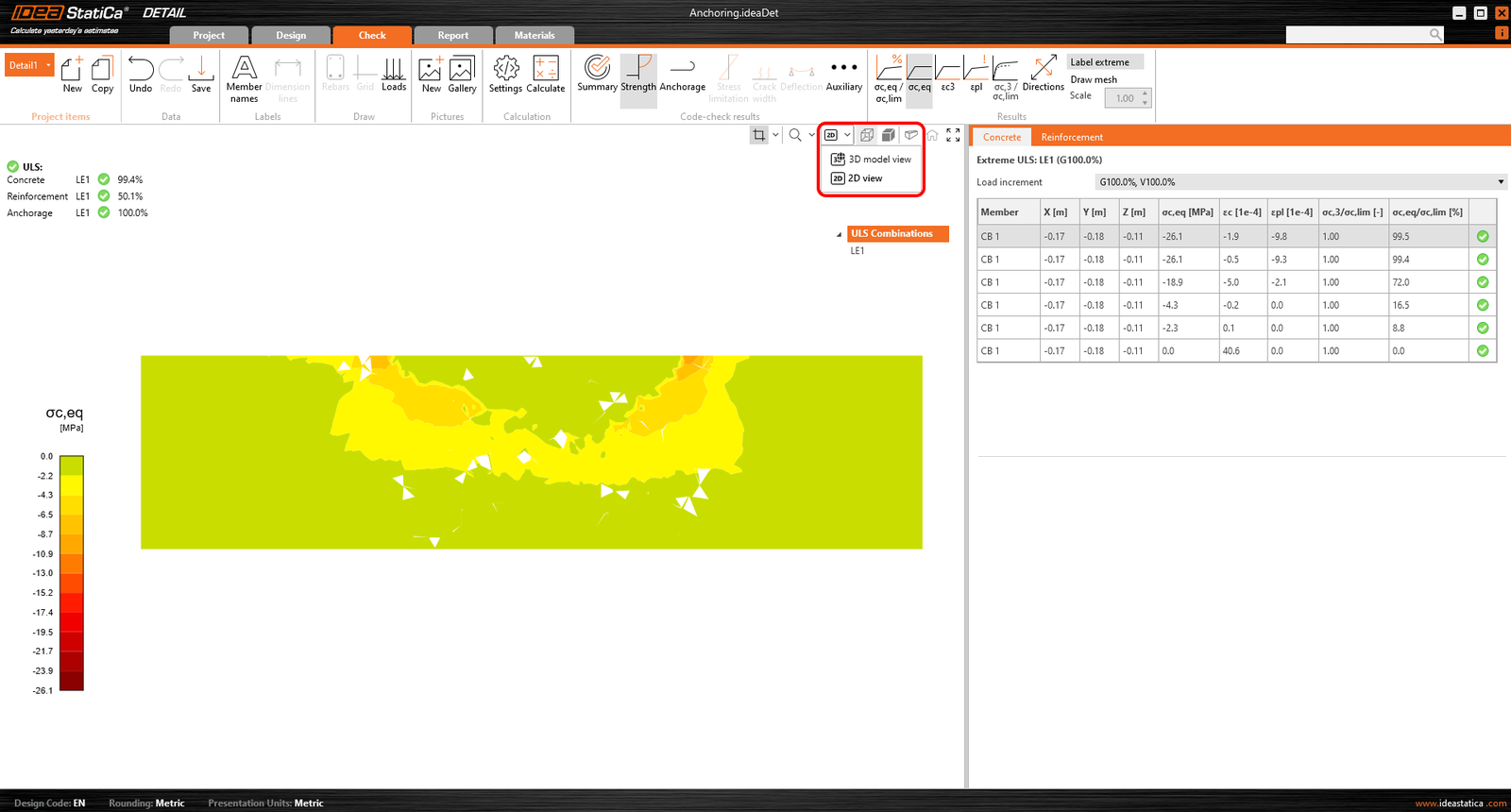
Sau există opțiunea de a comuta vederea din 3D în 2D și de a afișa secțiunea selectată în 2D pentru o mai bună claritate.
Verificarea tensiunilor
Pentru o mai bună înțelegere a rezultatelor și a teoriei implementate în Detail 3D, iconografia a fost îmbunătățită semnificativ. În secțiunea „Rezistență", la evaluarea tensiunilor din beton, veți găsi pictograme noi și, cel mai important, sfaturi explicative care descriu teoria de bază. Aceste sfaturi corespund bazelor teoretice.
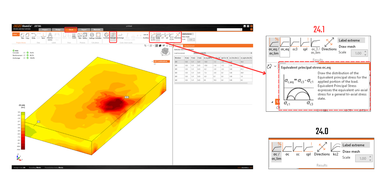
Lansat în IDEA StatiCa versiunea 24.0.2
Ca standard în aplicațiile noastre, toate rezultatele pot fi tipărite într-un raport generat automat, incluzând fundalul teoretic, paragrafe definite de utilizator și multe altele.