Unit test: Simple bending test on cantilevers
Introduction
This article presents a unit test for the 3D Compatible Stress Field Method (3D-CSFM) applied to cantilever beams with variations in length, reinforcement, and concrete grades. The 3D-CSFM enhances the established 2D-CSFM, both integral to IDEA StatiCa Detail. Released in beta, the 3D-CSFM adheres to the foundational principles of its 2D predecessor. The assessment of the FEA model is currently being refined to ensure that the results accurately reflect the appropriate behavior. Comparison comes from a series of unit test that were conducted during the process of development and include results from 2D-CSFM and analytical norms from Eurocode 2: Design of concrete structures - Part 1-1, chapter 6.1. The 3D approach in IDEA StatiCa Detail features two primary classes of models: the "wall element" and the "solid block." Both are further elaborated within the article, using standard settings in IDEA StatiCa Detail.
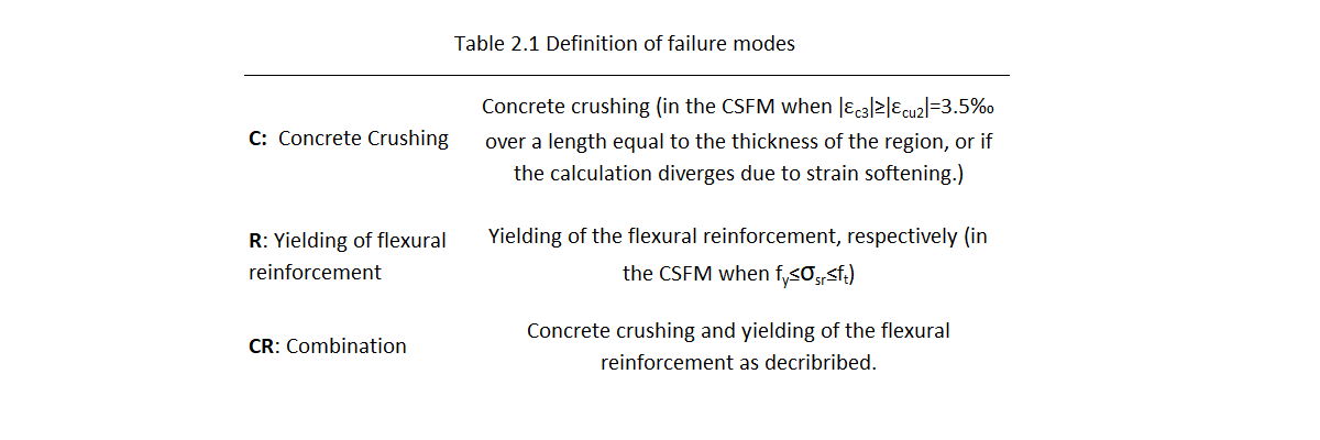
Definition of failure modes
To evaluate the performance of the 3D-CSFM in comparison to the 2D-CSFM and established analytical methods, we classify observed failure modes into three categories: Concrete crushing (C) and yielding of flexural reinforcement (R), or a combination of these two (CR). This classification allows for a structured comparison of failure mechanisms as predicted by different modeling approaches. Table 2.1 defines mentioned failure types by specifying material limit values. The models were specifically designed with robust shear reinforcement to exclude failure due to shear and focus solely on simple bending behavior.
Unit test set up
In the tests, the loads were defined differently based on the model type: as a line load measuring 0.3 m at the end of the beam for the 2D-CSFM, the 3D-CSFM wall element, as a surface load (0.3 x 0.3 m) at the end of the beam for the 3D-CSFM solid block, and as point load in the analytical approach with a location corresponding to resultant force of the previous types.
There are two types of setup in these sets: WC (Weak concrete) WR (Weak reinforcement).
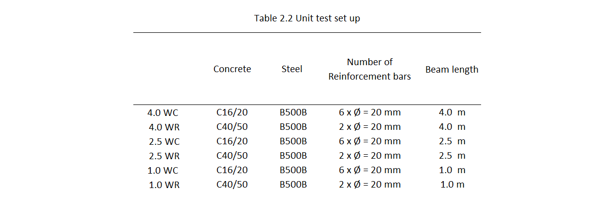
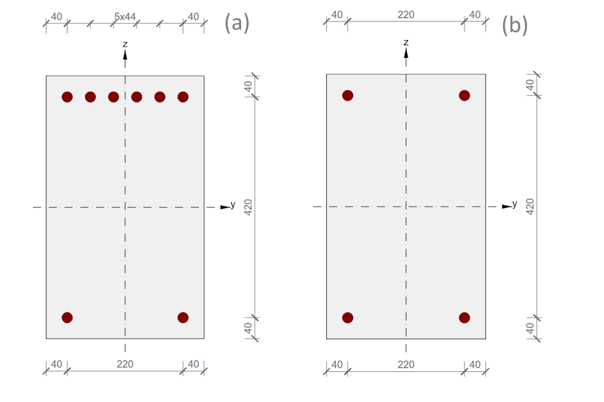
The flexural reinforcement in the models consisted of continuous reinforcing bars with a diameter of Ø = 20 mm. The WR (Weak Reinforcement) model utilized two reinforcement bars, while the WC (Weak Concrete) model included six. The shear reinforcement, made up of Ø = 10 mm stirrups spaced 100 mm apart, was deliberately designed to be robust, thereby precluding any shear failure mode. The shear reinforcement is consistent for all the models.
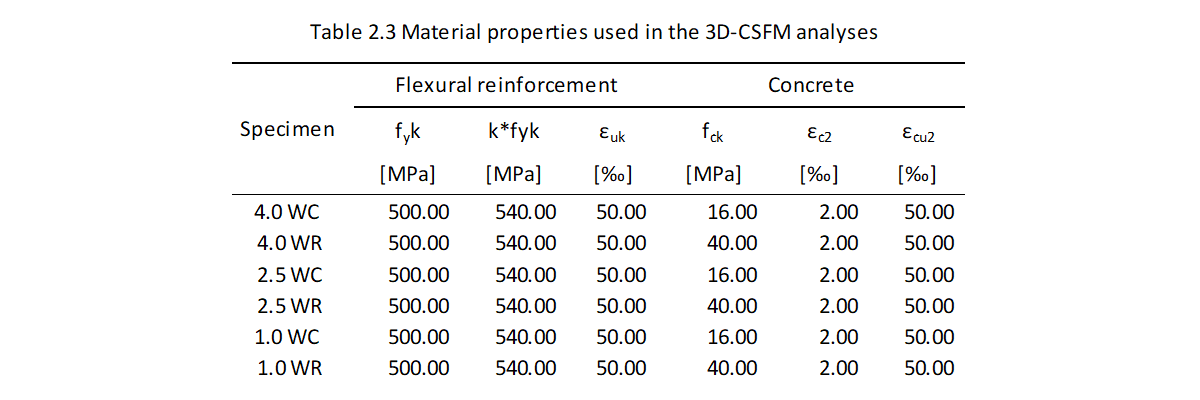
The WC are of a concrete grade C16/20 featuring six reinforcement bars, and WR setups using concrete grade C40/50 with two reinforcement bars. The lengths of the test examples varied, measuring 1.0m, 2.5m, and 4.0m.
Considering all the variations mentioned, this unit test resulted in six different models. These models are described in detail in Table 2.2.
\[ \textsf{\textit{\footnotesize{Fig. 1.1\qquad Cross-section set ups: (a) - WC, (b) - (WR)}}}\]
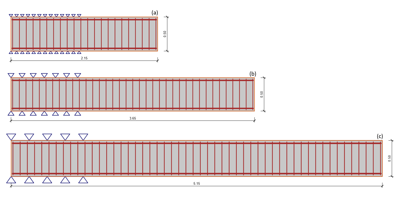
\[ \textsf{\textit{\footnotesize{Fig. 1.2\qquad Length set ups: (a) - 1.0 m, (b) - 2.5 m, (c) - 4.0 m}}}\]
Material properties
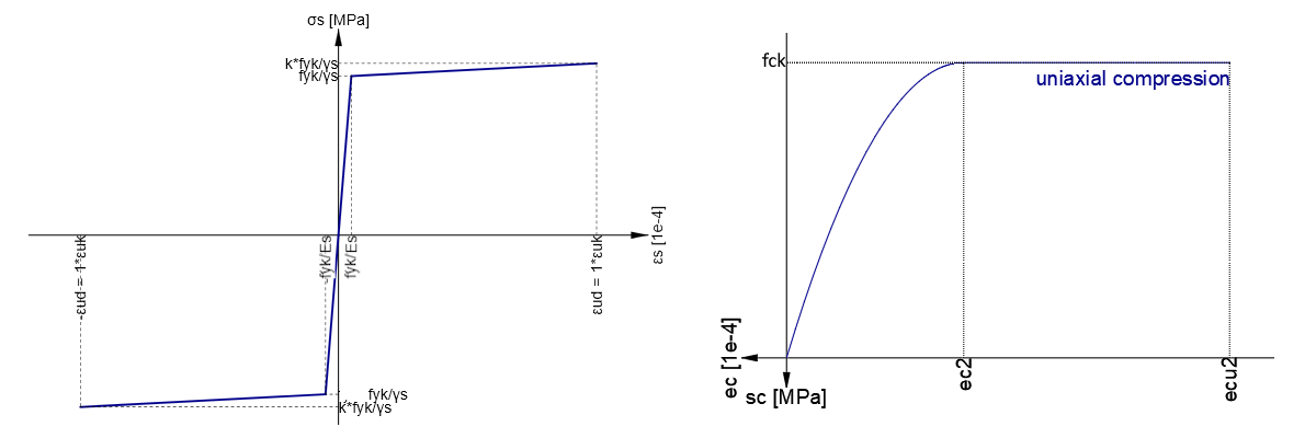
The material properties of concrete and flexural reinforcement used in the CSFM analysis are summarized in table 2.2. The yield stress (fyk) and the ultimate stress (k*fyk) of the reinforcement as well as the compressive strength (fck), plastic strain(ɛc2) and limit plastic strain (ɛcu2) of the concrete and were selected to clearly illustrate the behavior of the materials under stress.
\[ \textsf{\textit{\footnotesize{Fig. 1.3\qquad Stress strain diagrams of materials: (a) Stress-strain diagram of reinforcement B500N, (b) Stress-strain diagram of concrete C16/20 and C40/50 }}}\]
Modelling with 3D-CSFM
In the IDEA StatiCa Detail application, there are model types: the 2D model type utilizes the established CSFM method, while the 3D model type features the newly developed beta version of the 3D-CSFM method. Within the 3D model type, users can choose between two classes of models: 3D Wall and Solid Block.
- Each class of 3D models within IDEA StatiCa Detail utilizes a different mesher, specifically chosen and optimized for fast and stable calculations. The shape and size of the mesh elements are finely tuned to enhance the performance and accuracy of model computations.
- Both 3D model classes in IDEA StatiCa Detail use tetrahedron elements for meshing. Specifically, the 3D wall class features mesh elements shaped in a ratio where one dimension is significantly smaller than the other two, effectively mirroring the shape of a wall. This design choice optimizes the mesh for accurate representation and analysis of wall-like structures. The model class "Solid Block" general size mesh elements, which are designed to provide a balanced approach to meshing that is suitable for a wide variety of solid geometries. This method ensures efficient and effective analysis across different scenarios.
- The material of the 3D Wall model is designed as an orthotropic material. This means that the lateral shear stress is transferred by the concrete, accommodating the unique structural behaviors typical of wall elements.
- To ensure optimal meshing for the 3D wall model class, tailored for wall structures, the mesh multiplier factor was adjusted to 0.7. This was crucial to match the number of elements with those in the Solid block model class, which was set up for the unit test using default settings.
Geometry
When defining the geometry of the tested specimen in the IDEA StatiCa Detail application (both 2D and 3D environment), the length was set as the variable length (1.0m, 2.5m, 4.0m) plus an additional 1.15 meters. On this additional length of 1.15 meters, supports were defined on top and bottom surfaces with rigid stiffness in all directions.
Loads
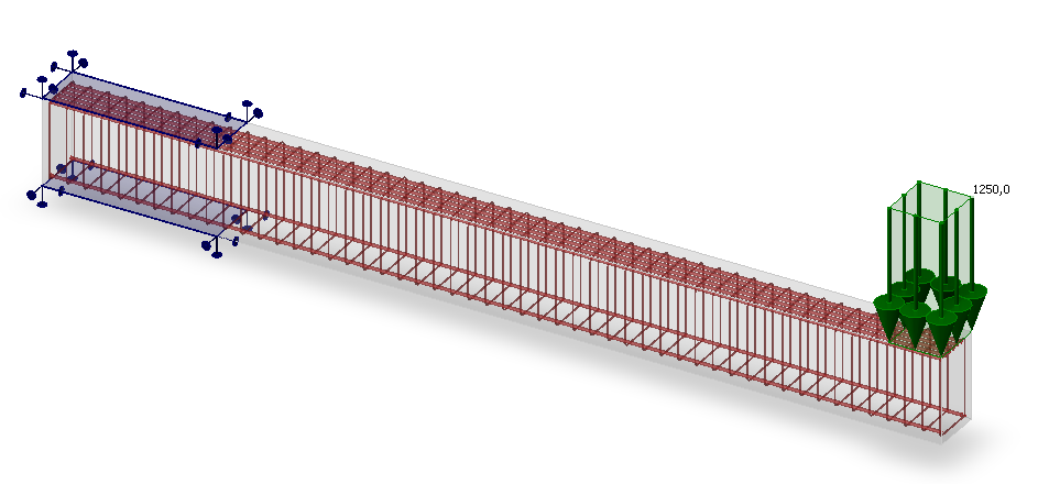
In the tests, the loads were defined differently based on the model type. In the 2D model type, the load was applied as a line load measuring 0.3 m at the end of the beam. In the 3D environment on 3D Wall model class, the load was applied as a line load measuring 0.3 m at the end of the beam. In the 3D environment for the solid block model class, the load was applied as a surface load measuring 0.3 x 0.3 m at the end of the beam. In the analytical approach, a point load was utilized, positioned to correspond with the resultant force derived from the other model types.
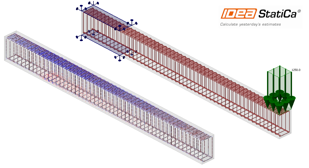
\[ \textsf{\textit{\footnotesize{Fig. 1.4\qquad Surface load on Specimen: 3D Solid Block WC 4.0}}}\]
Calculated Critical Load
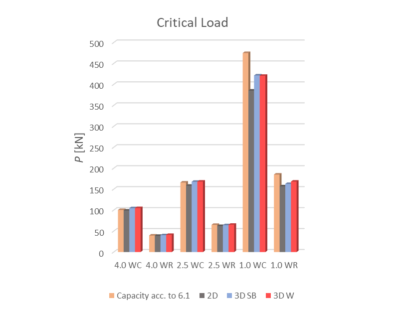
In the comparison figure 1.5 featuring six model variants distinguished by length and options of WC (weak concrete) and WR (weak reinforcement), the 3D methods generally exhibit a solid match. Notably, the 3D Wall model class's mesh factor was adjusted to 0.7 to equalize the number of elements across the model's height, making it comparable to the solid block general model. The 3D results are slightly higher than the 2D CSFM solutions, as expected due to the inclusion of triaxial stresses and simplifications in 2D CSFM. Analytical results align with 3D and 2D CSFM in most cases, except for higher values in short 1.0 m WC and WR scenarios, where shear interactions (concrete strut in compression) significantly impact but are overlooked analytically, explaining the lower values from 3D models. This is corroborated by 2D CSFM results.
\[ \textsf{\textit{\footnotesize{Fig. 1.5\qquad Calculated Critical Load}}}\]
Load-deformation response
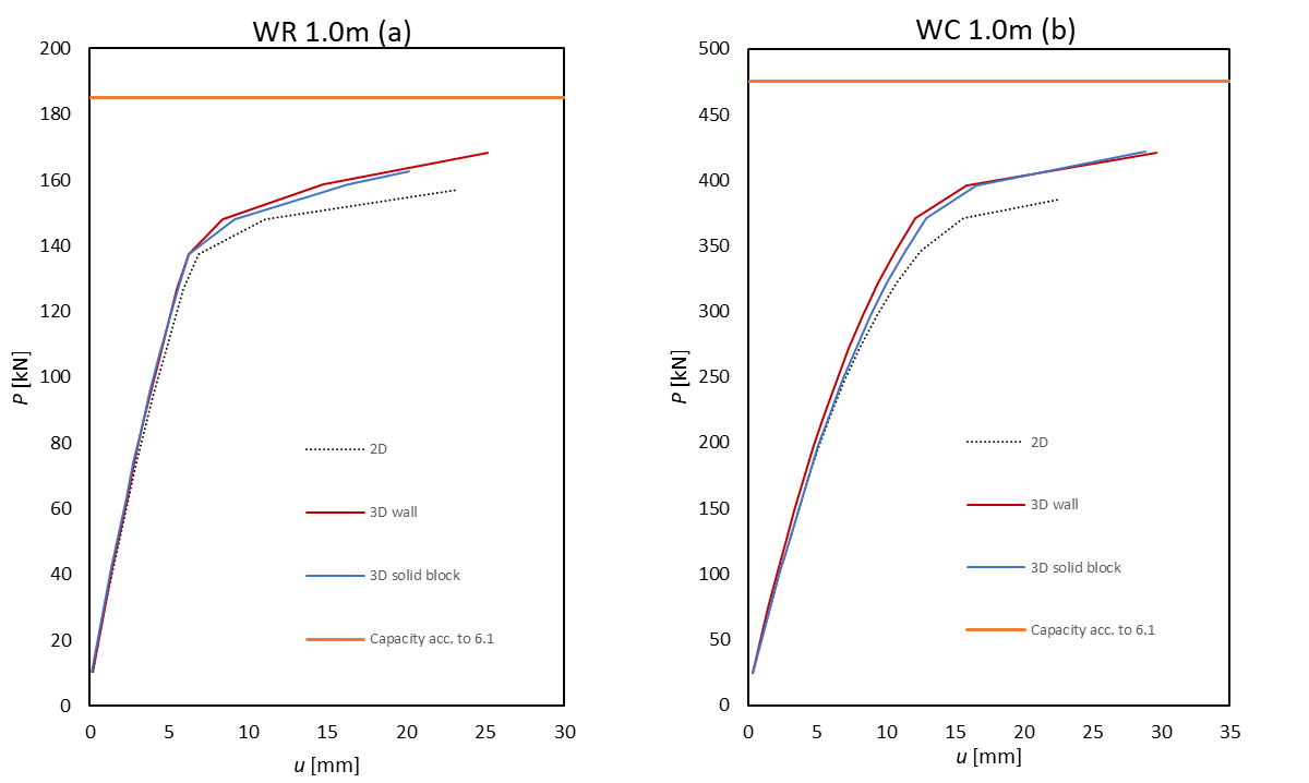
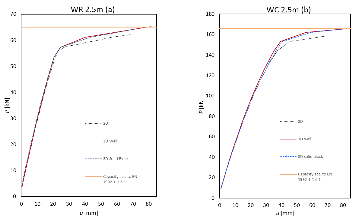
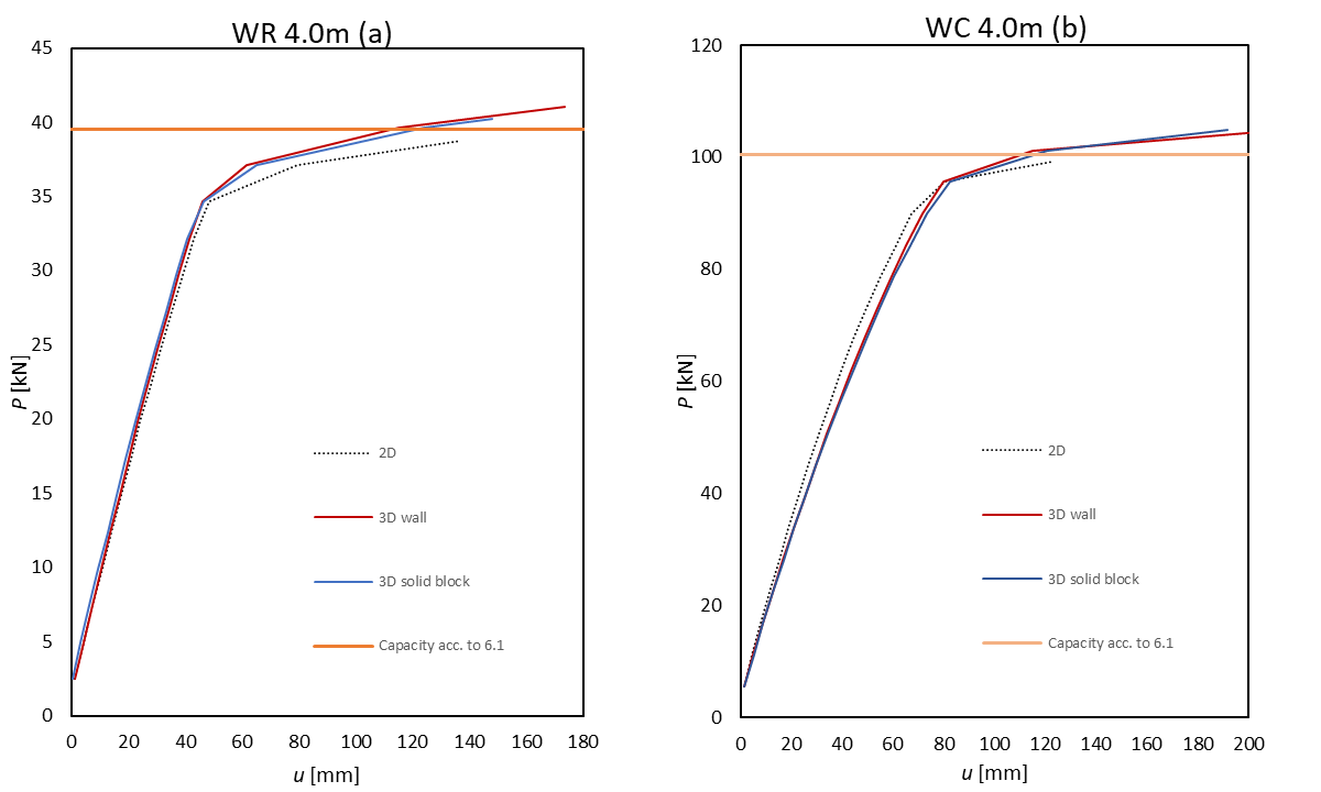
The comparison of diagrams across the different methodologies reveals distinct behavior patterns for each. The 2D-CSFM is depicted with a black dotted line, the 3D-CSFM Wall model class with a red solid line, the 3D-CSFM Solid block model class with a blue dotted line, and the standard approach based on section check according to EN with an orange solid line. Displacement and forces were measured from the end of the cantilever.
In the diagrams, the analytical results are represented by a constant line, indicating that only a single value for the bending resistance of the given specimen is obtained. This portrayal underscores the static nature of analytical results in contrast to the incremental approach for nonlinear solution.
In Figure 1.6, there was a strong correlation between the results from the 3D-CSFM and the 2D-CSFM across all tests, aligning well within the range of available measurement data. The analytical approach, however, showed higher force values, anticipated due to its exclusion of shear resistance interaction, especially significant given the beam's 1.0 m length. This highlights the analytical method's limitations in fully capturing the comprehensive forces affecting the specimen.
\[ \textsf{\textit{\footnotesize{Fig. 1.6\qquad Calculated Load-Deformation respond: (a) WR 1.0, (b) WC 1.0 }}}\]
In Figure 1.7, which captures load-deformation responses for models with a length of 2.5 meters, all methods show a great match in results. Both 3D models align closely with the analytical results calculated by EN. Comparatively, the 3D method exhibits slightly higher values than the 2D CSFM solution, yet these differences remain within a tolerable margin.
\[ \textsf{\textit{\footnotesize{Fig. 1.7\qquad Calculated Load-Deformation respond: (a) WR 2.5, (b) WC 2.5}}}\]
In the final Figure 1.8, a good correlation is observed among the methods, with the 3D models displaying higher values than both benchmark results. These variances, however, remain within acceptable limits.
\[ \textsf{\textit{\footnotesize{Fig. 1.8\qquad Calculated Load-Deformation respond: (a) WR 4.0, (b) WC 4.0}}}\]
\[ \textsf{\textit{\footnotesize{Fig. 1.9\qquad Calculated value of reinforcement stress on WR 4.0 different model types: (a) 2D, (b) 3D - Solid Block, (c) 3D - Wall}}}\]
Conclusion
Given the close alignment between the 3D-CSFM results and those from 2D-CSFM and analytical methods, several conclusions can be drawn:
- The newly developed 3D-CSFM, although still in its beta version, is already demonstrating promising results.
- In the load-deformation response and critical load evaluations, the 3D-CSFM shows a strong alignment with the analytical approach where shear effects are minimal. However, in scenarios where shear interactions significantly influence structural resistance, a decrease in resistance is observed. This is an expected outcome and validates that the solver is performing correctly.
- In the analysis of a cantilever beam subjected to simple bending, both classes of 3D models—the Wall Element and Solid Block—exhibit similar behavior. This consistency underscores the robustness of the 3D-CSFM approach in modeling such structural scenarios.


