Why is 5% strain limit used in material diagram for AISC?
In IDEA StatiCa Connection, the plates are modeled using shell elements with an elastic-plastic material diagram. The material behavior is based on the von Mises yield criterion. It is assumed to be elastic before reaching the yield strength, fy. The ultimate limit state criterion for regions not susceptible to buckling is reaching a limiting value of the principal membrane strain. The value of 5 % is recommended in codes (e.g. EN1993-1-5, App. C, Par. C.8, Note 1).
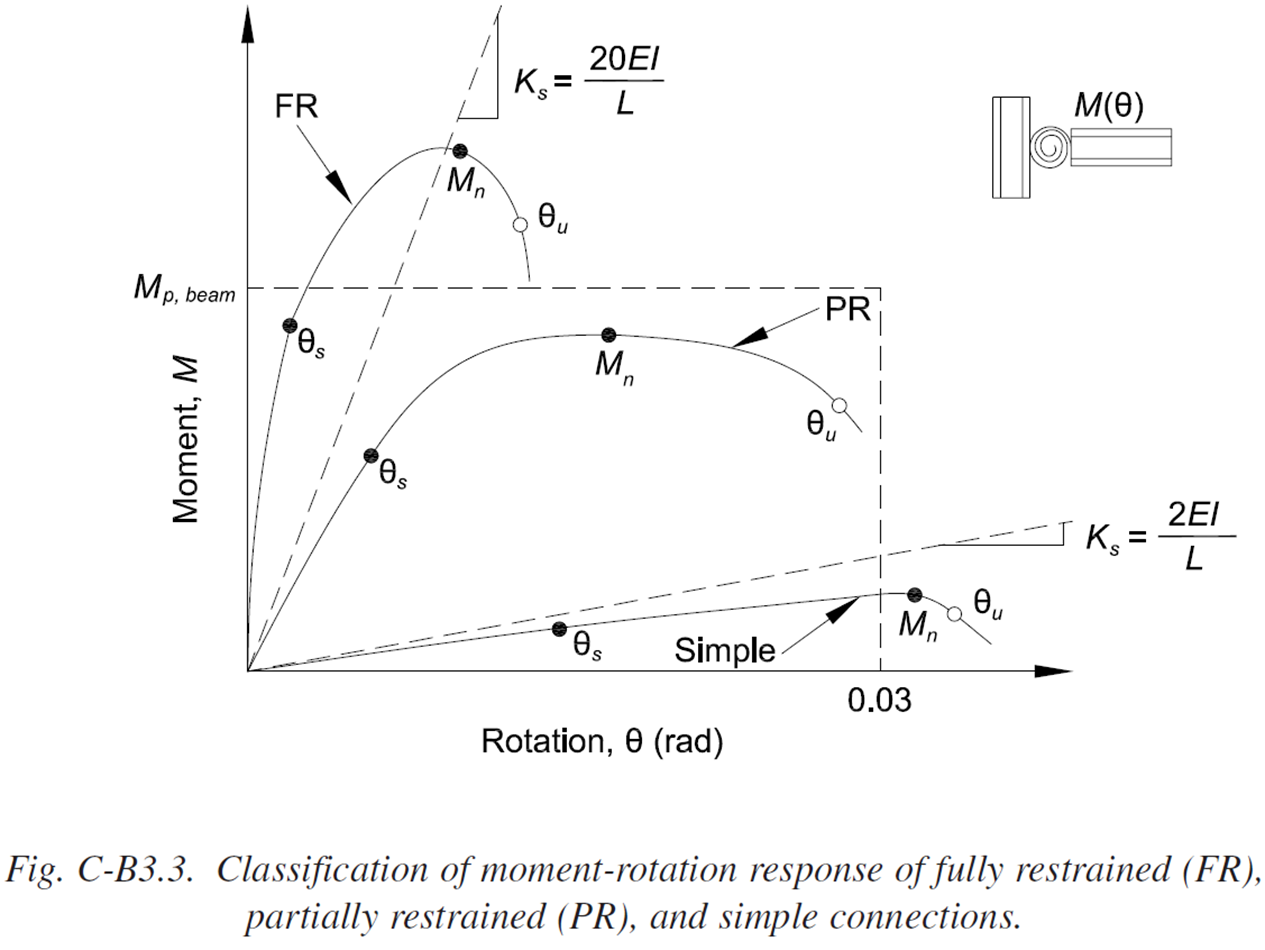
ANSI/AISC 360-16 uses a different approach. In Chapter B – Design requirements, there is an article: “Connection Strength. The strength of a connection is the maximum moment that it is capable of carrying, Mn, as shown in Figure C-B3.2. The strength of a connection can be determined on the basis of an ultimate limit-state model of the connection, or from physical tests. If the moment-rotation response does not exhibit a peak load then the strength can be taken as the moment at a rotation of 0.02 rad (Hsieh and Deierlein, 1991; Leon et al., 1996).”
Figures are taken from ANSI/AISC 360-16, Comm. B3, p. 332, 333.
An example of a welded connection in IDEA StatiCa is presented:
The design bending resistance of this connection, according to this article in AISC 360, is determined as the bending moment at the rotation of 20 mrad (MRd = 408.5 kip-in). This resistance nearly equals to the bending resistance determined by limiting plastic strain to 5 % as suggested by EN 1993-1-5 (MRd = 402.5 kip-in).
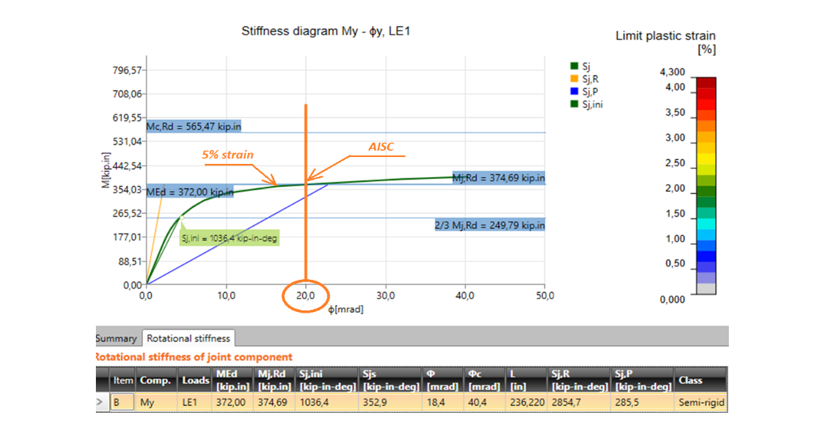
Another example of a bolted connection shows similar results:
Again, the resistance determined by rotation 20 mrad (MRd = 372 kip-in) closely coincides with the resistance determined by limiting plastic strain to 5 % (MRd = 374.7 kip-in).
Conclusion
ANSI/AISC 360 leaves finite element modeling (see Appendix 1 – Design by advanced analysis and Chapter B – Design requirements – 4. Design of connections and supports – Structural analysis) to engineering judgment. The use of bilinear elastic-plastic material diagram for steel plates and the limitation of the plastic strain is a simple and reasonable approach allowing to solve all types of generally loaded connections. The results closely coincide with the approach suggested specifically by ANSI/AISC 360.
The limit of plastic strain can be edited in Code setup, although verification studies have been performed with a recommended value of 5 %. The value has generally low effect on the resistance of the connection. The difference in bending moment resistance between 2% limit strain and 10% limit strain is only 7 % in the second example of bolted connection.
References
ANSI/AISC 360-16 (2016), An American National Standard – Specification for Structural Steel Buildings, AISC, Chicago, 676 p.
EN1993-1-5 (2006), Eurocode 3: Design of steel structures - Part 1-5: General rules - Plated structural elements, CEN, Brussels, 53 p.
Hsieh, S.H. and Deierlein, G.G. (1991), “Nonlinear Analysis of Three-Dimensional Steel Frames with Semi-Rigid Connections,” Computers and Structures, Elsevier, Vol. 41, No. 5, pp. 995–1,009.
Leon, R.T. (1994), “Composite Semi-Rigid Construction,” Engineering Journal, AISC, Vol. 31. No. 2, pp. 57–67.


