Troubleshooting IDEA StatiCa Connection models
1. Analysis status
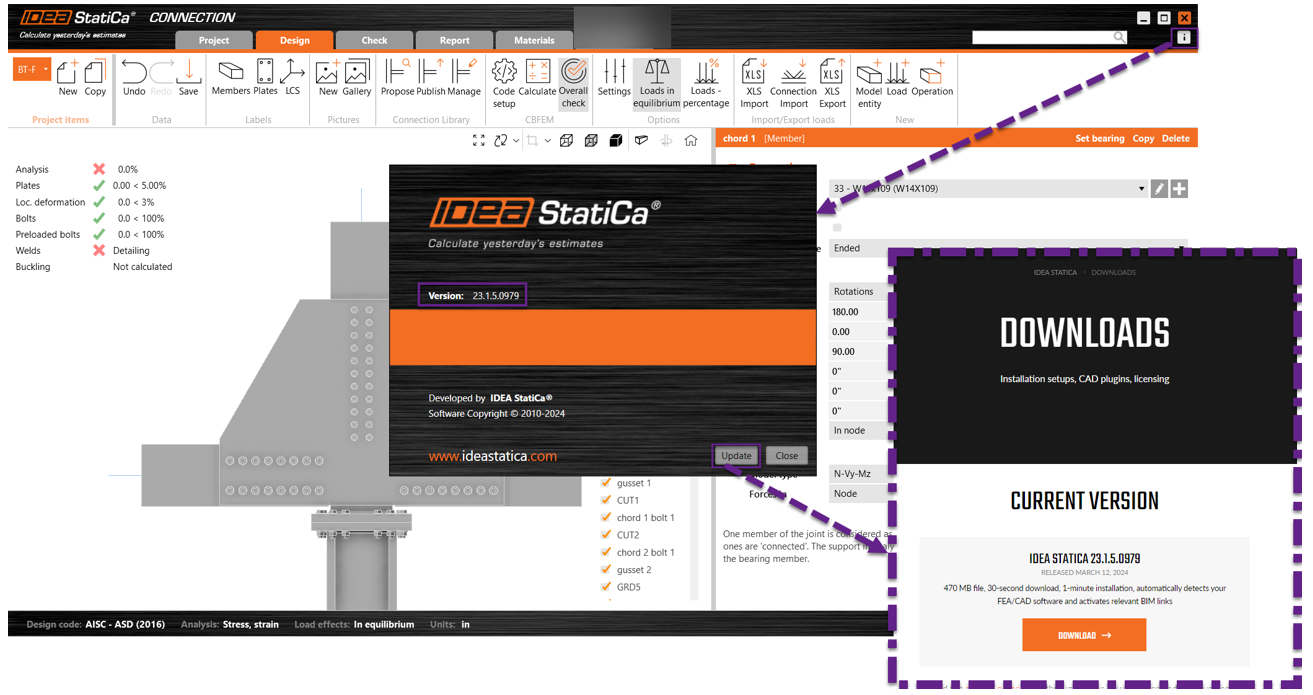
Once we get the model with the issue, we click on the calculate button. The first thing to review is the analysis status and the software version.
After clicking on the calculate button, you can see the analysis status at the top left side of the modeling window. From there, you get the first insight into what is happening in the model, such as utilization ratios, analysis errors, singularities, percentage of the applied forces, etc. I will explain these later during the checklist points.
Also, we always ask the user what software version they use because sometimes upgrading the software will help solve the issue. To see the software's version, click on the information icon. There, you can see the exact version. If you click on the update button, that will lead you to the download page, where you can see the latest version and download the latest if you are not in that one. Test it to see if your problem is solved in that new version.
2. Singularities
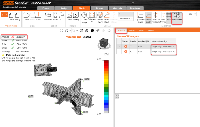
When you see the word singularity on the top left side of the modeling window, do not panic! The best thing to do is go to the Check tab for more information. So, what is a singularity? This happens when the mesh is created, but the analysis can’t start because one of the elements is not connected to the joint or there is a gap or overlapping of connecting items, and I can keep going with the situations that create a singularity; I won’t go through all of them as the objective of this guide is to tell you where to find more information and how to fix it.
When you are in the Check tab, see that the analysis tab has info about where the singularity is happening, in this case, M3. Also, if you activate the deformed shape when you get a singularity, you can see what plate or member is creating the singularity.
3. Modeling tab - member boundary conditions
If the singularity is not that obvious, then go back to the modeling tab and review every member in the model:
- Bearing member: Offsets=0. Don’t move the support member; move the other members around.
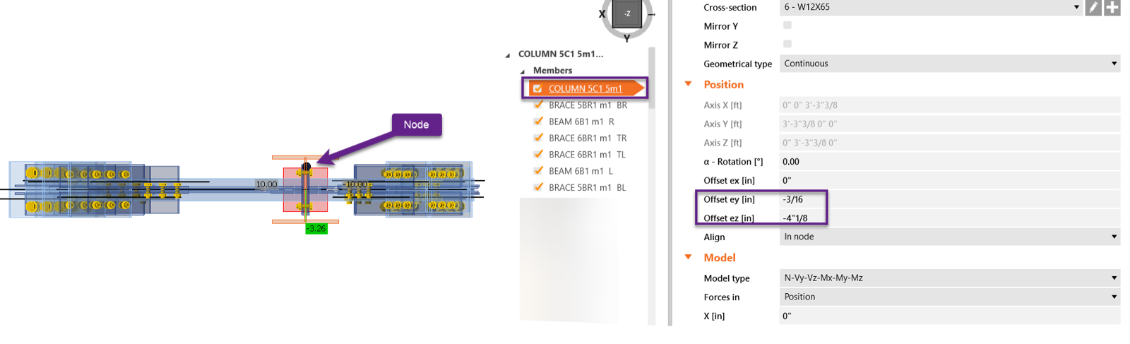
- Offset ex=0 - Do not use this input unless there is no other option. Instead, use operations.
- Model type: make sure you selected the appropriate option. You can see more info here.
- Force position: Unsure where to locate the force; read more info about this input here.
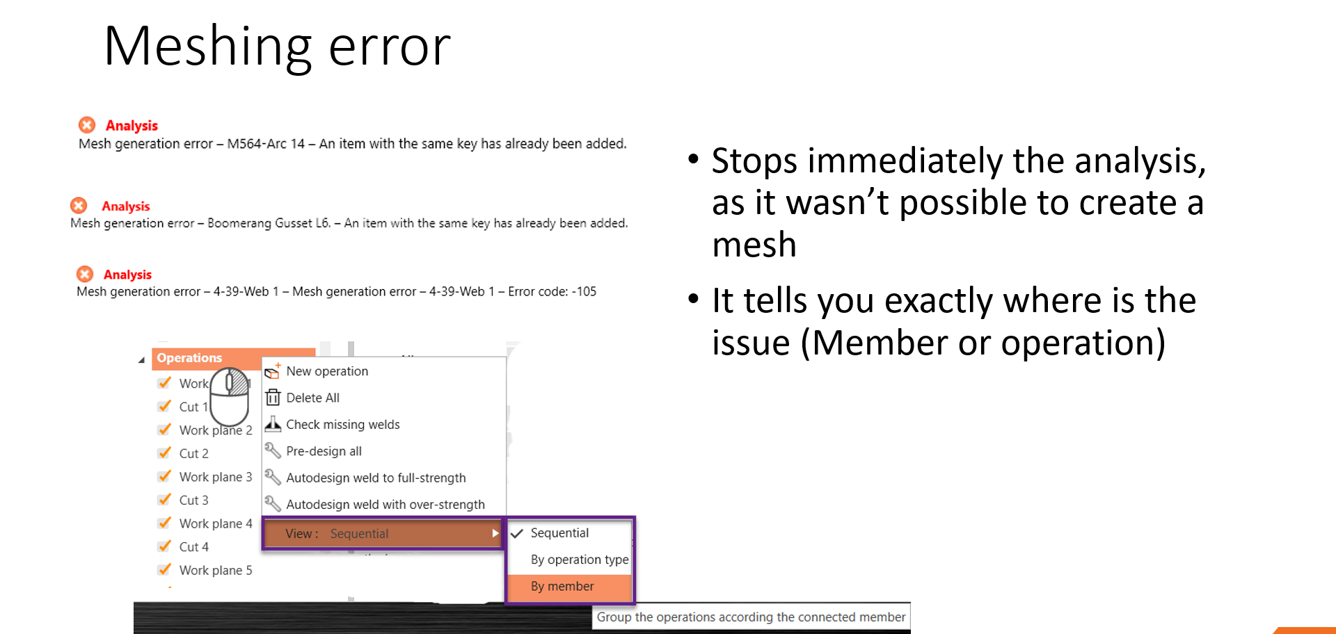
4. Meshing error
Let’s suppose it wasn’t a singularity but a meshing or operation error. Again, this will be mentioned at the top left side of the modeling window. If you get an error message, that message usually tells you what operation is creating the issue.
- The meshing errors immediately stops the analysis, as creating a mesh was impossible.
- It tells you exactly where is the issue (Member or operation)
- One tip is that you can view the operations by member, which can help you map the operations related to certain members.
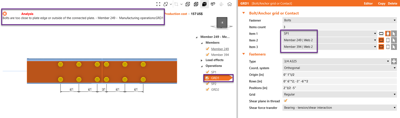
5. Check the bolt operations
There are some common errors related to bolts:
- Incorrect plate selection in a grid operation
- The maximum allowable gap between plates connected by bolts is 1/16”
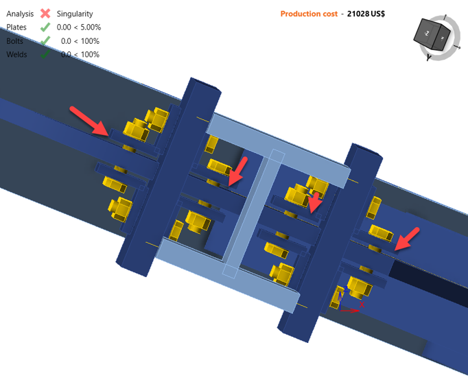
- Slotted hole in the direction of the load: when using slotted holes, the direction of the slot is released. That can create a singularity as there is no restraint in that direction.
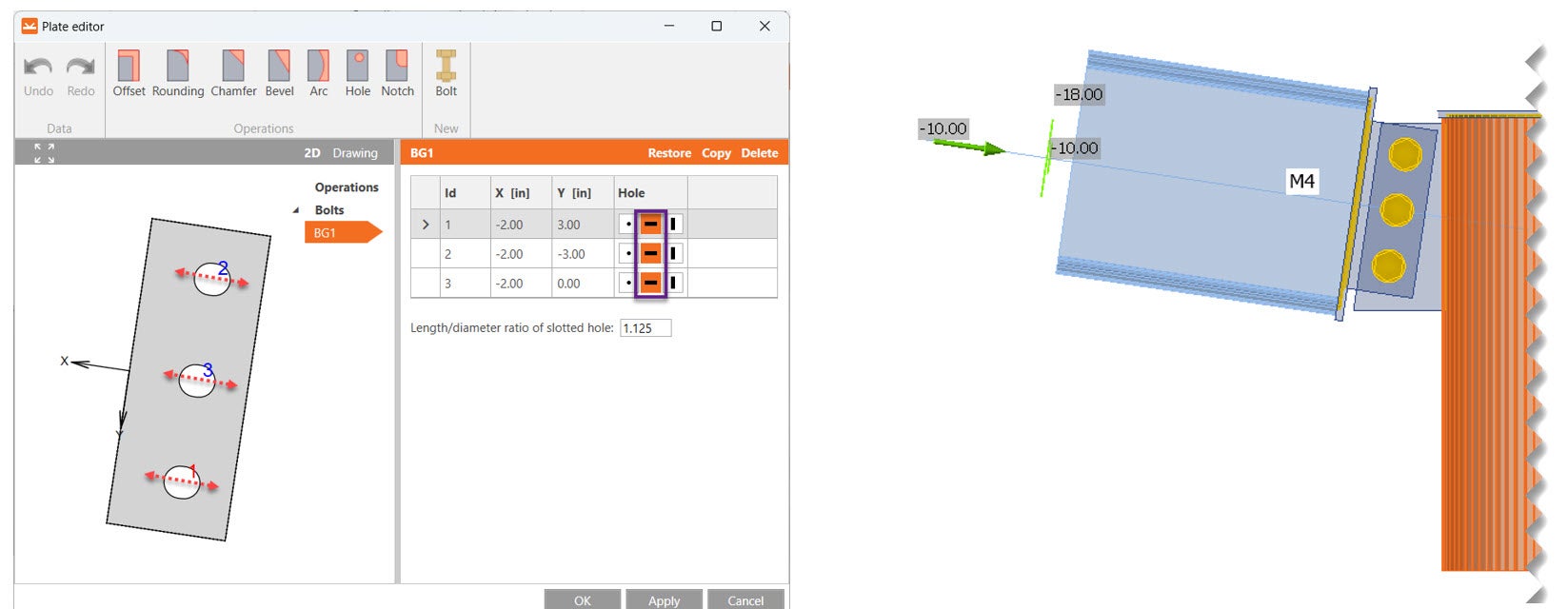
- Opening in the same position as the bolt
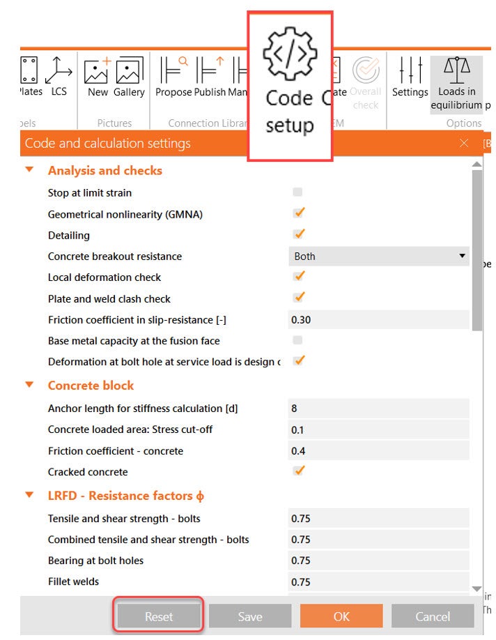
6. Code set up
Another usual issue that we got at the help desk is the Code setup modification. Some options can influence the analysis within the code setup in the design tab, so I always try to reset the code setup properties to the default options. An important aspect of Code setup is that the configuration applies to all the project items in the file.
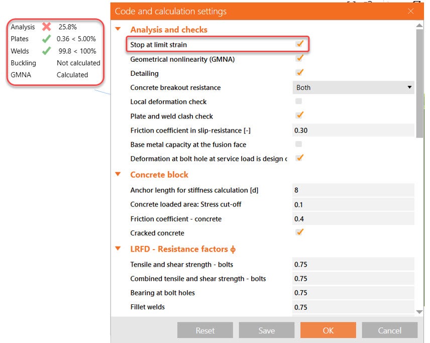
The analysis didn’t get to 100%
When the analysis doesn’t finish until 100%, the stop-at-limit strain is one item to check under code setup. If that is active, the analysis will stop whenever something is near the failure. In this case, the welds utilization ratio was 99%, so the analysis stopped, and only 25% of the loads were applied. So, if I uncheck the stop-at-limit strain, the software will run 100% of the loads so that you can see the whole picture.
What if the stop-at-limit strain is not active and still the analysis stops?
GMNA - Geometrical nonlinear analysis
Then you observe that your bearing member is a hollow section and your model has large deformation. The best guess is that it will be a GMNA issue. What is GMNA?
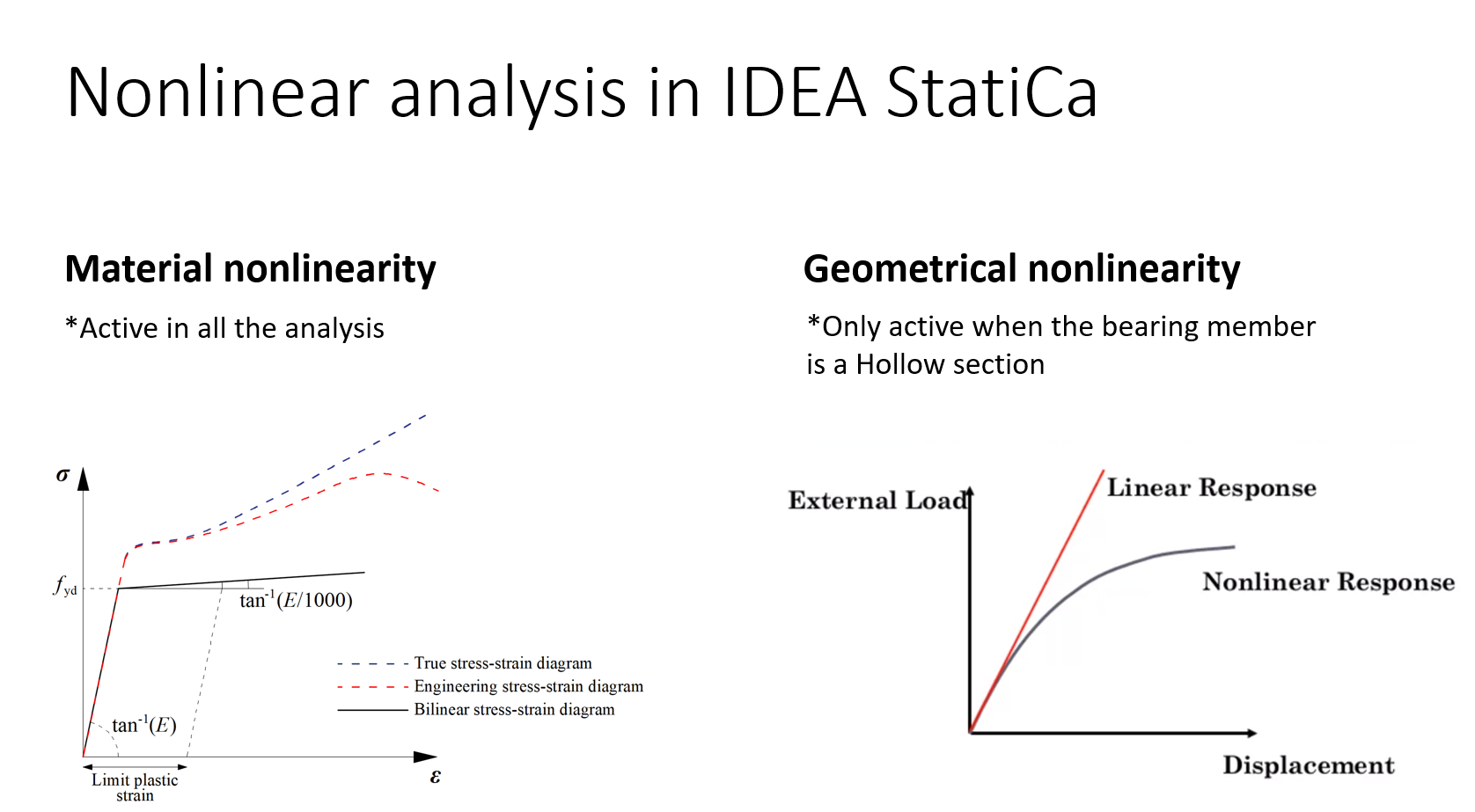
IDEA StatiCa can run both Material and geometrical non-linear analyses. The material non-linearity applies to steel, which means its behavior is not linear. You can see the curve we use in the first diagram.
The geometrical nonlinear analysis applies to the nonlinear deformation of certain profile sections, such as hollow sections. So, both types of nonlinearities are used when using a hollow section as a bearing member.
When using HSS members as bearing members, we use GMNA, which stands for advanced geometrically nonlinear analysis. This provides more precise results for models mainly with hollow section members. The GMNA solver is used only when the bearing member has a hollow section. GMNA analysis can be turned on/off in the Code setup.
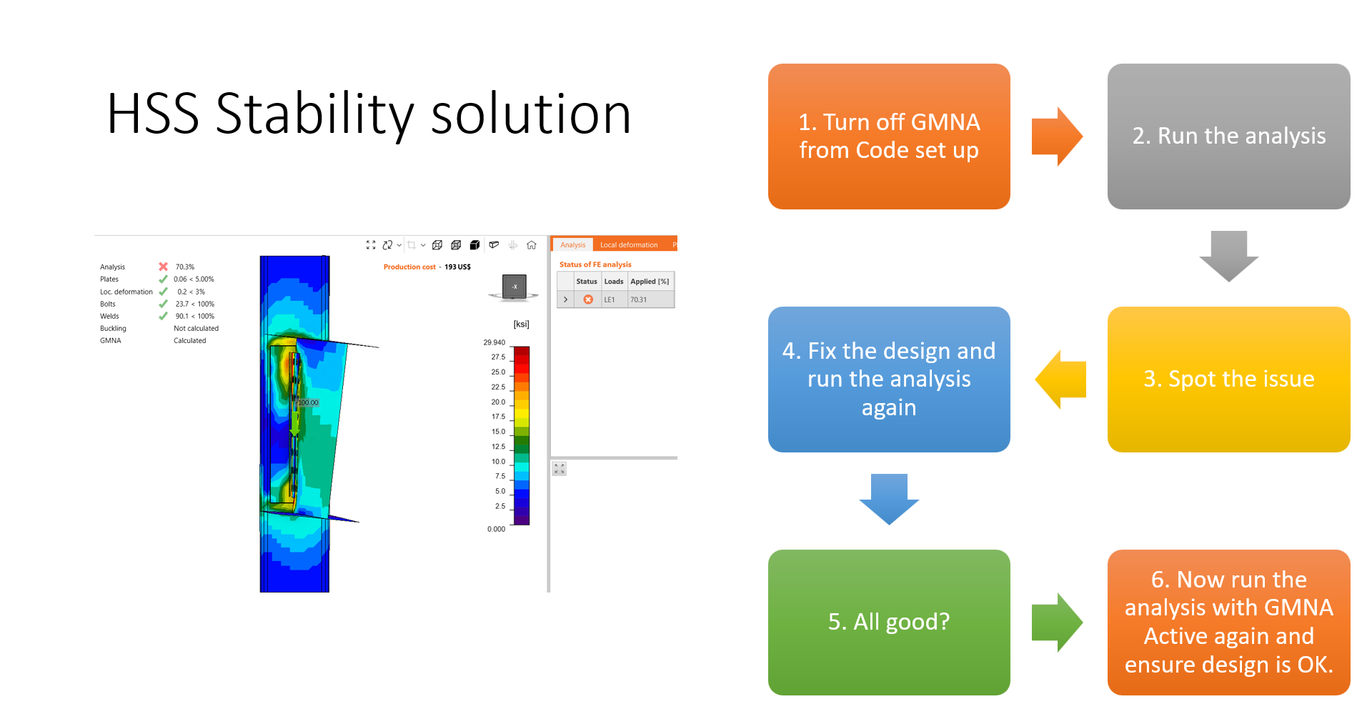
When the connection is overloaded, the hollow sections might lose stability, which results in a break of the analysis at the current percentage of applied loads. By disabling the GMNA in the Code setup, the analysis finishes with 100%, revealing the failure of the hollow section and other parts of the connections.
Here are the steps to get the analysis to work when running GMNA:
- Look at the Code setup and confirm that Stop at limit strain is not active
- Look at the deformed shape, spot large and unrealistic deformations, review the operations related to the large deformations, and fix the modeling issue.
- No modeling errors nor large deformations? If the bearing member is a hollow section, the analysis didn’t converge due to large deformations.
- Turn off GMNA under code setup and re-run the analysis. Spot the design issue, fix it, and re-run it. If the design is good, return to the Code setup, activate the GMNA again, and ensure the design is OK.
7. Nonconformity
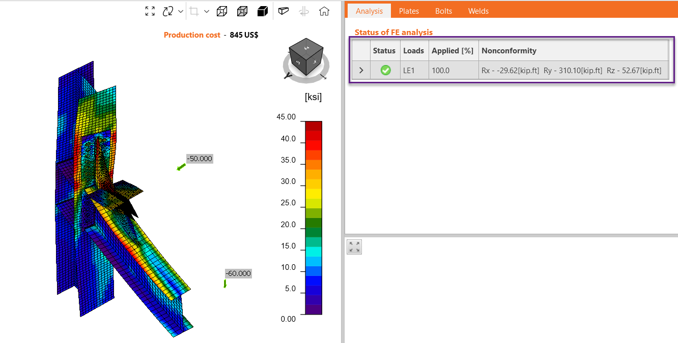
The analysis finishes OK, but you notice a nonconformity in the analysis tab.
The nonconformity table shows the reactions on the model that weren’t considered due to the model type selection of certain members.
The tab shows nonconformities from all members of the model, and the force values are displayed in the global coordinate system.
See the following example: the beam and bracing are N-Vy-Vz, which means the member can transfer only normal force N and shear forces Vy and Vz, and both members have shear forces in and out of the plane. The moments along the members were restrained, but the rotation still occurs at the node. The nonconformity reactions help you to assess the correct selection of model type. In this case, the reactions are higher than the applied loads, so it means the choice of model type wasn't appropriate.
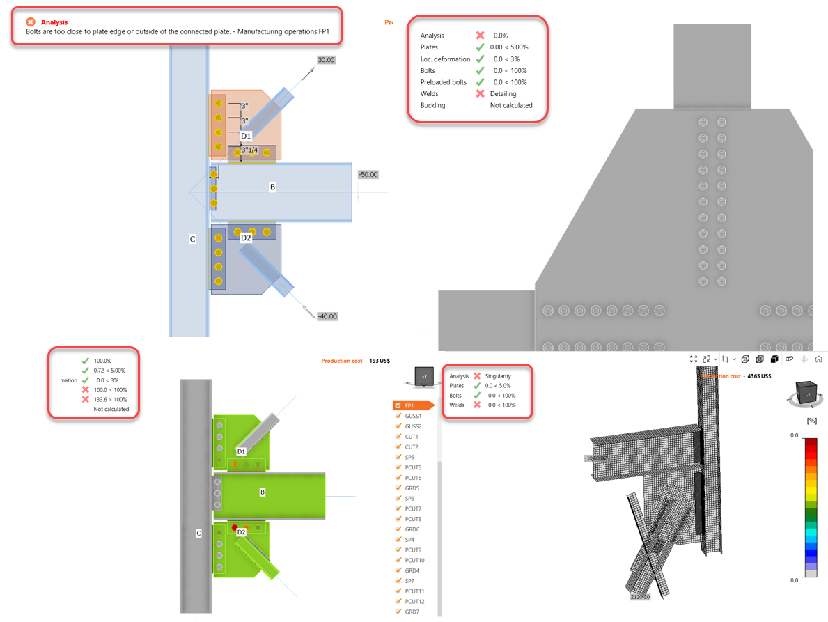
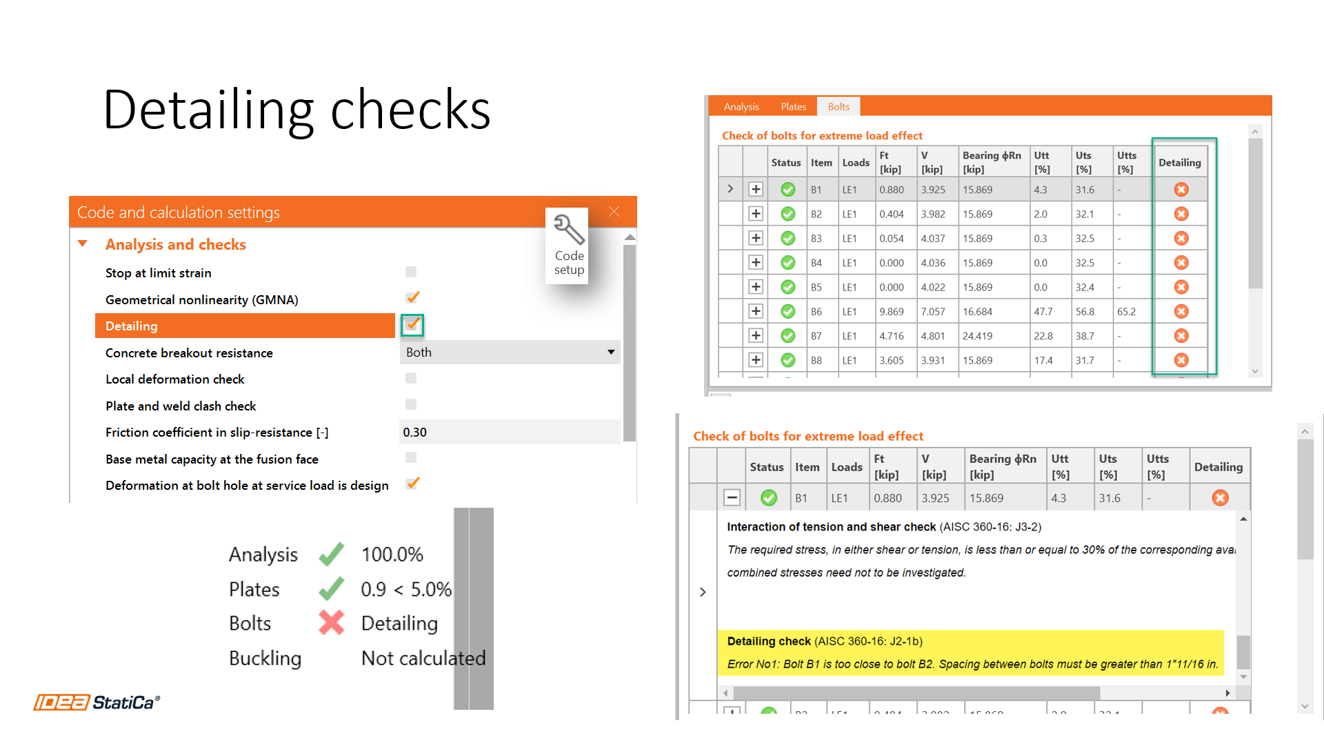
8. Detailing warning
IDEA StatiCa checks bolt spacing and weld sizes required by AISC. If one or more detailing checks do not comply, the software will tell you that there is a detailing warning. Please take a look at the following picture.
To learn more about the bolts or welds that don't comply with the code, go to the Check tab>Bolt/weld tab results>Review the detailing column and find the item failing. Click on the plus icon to open the calculation report and see the detailed warning.
9. Order of operations
It is essential to remember as you are building a connection that only operations above the current operation can be used in the current operation. I know that sounds like a circular sentence, but when you look at the list of operations in a model, you can't add a weld to a plate that is lower in the list. In this case, you need to be sure the plate operation is added and then add the weld. The order of operations matters and can affect the analysis.
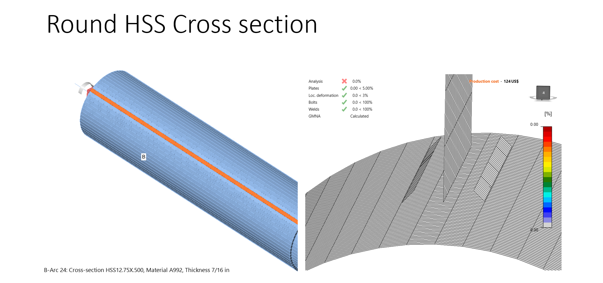
10. Round HSS cross-section modeling issue
When using the HSS cross-section in the application, you can see that vertical plate strips form it. That is convenient for the meshing procedure, but those strip mesh elements sometimes do not coincide with another mesh line, specifically when another perpendicular element is connected. Like in the following example:
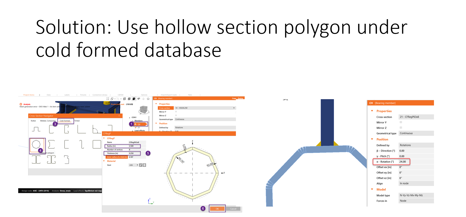
One workaround is to use a hollow section polygon under the cold-formed database. With that type of section, the plates are workable.
If you still need help with the model after reading the article, remember that we have the best technical support in the software industry! You can always submit a user case through our portal, and you will get a fast response.
A webinar about this topic was recorded here.