Angle seat connection
Type of connection: Double angle cleat connection
Unit system: Metric
Designed acc. to: AS 4100
Investigated: Bolts, base metal
Plate material: Grade 300
Bolts: M20 Grade 8.8
Example taken from: B. Kirke, I.H. Al-Jamel. Steel Structures: Design Manual To AS 4100, 2004 – Chapter 9.4.1.2
Geometry
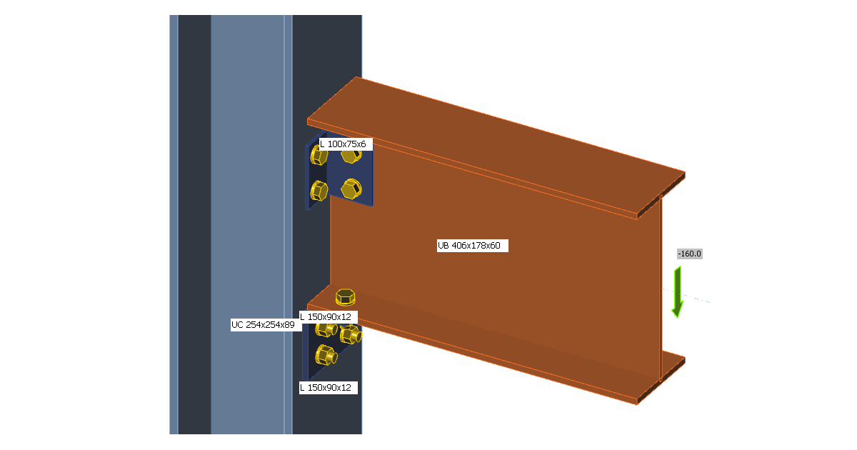
Beam UB 406×178×60 is connected to column UC 254×254×89. The beam is positioned on a seat made by angle L150×90×12. The web of a beam is connected to the column flange by another angle L100×75×6. M20 bolts grade 8.8 are selected.
Applied load
Shear load 160 kN is applied at the beam at the position of the centre of gravity of bolts on the beam web.
Results of manual calculation
The results of B. Kirke, I.H. Al-Jamel. Steel Structures: Design Manual To AS 4100, 2004 – Chapter 9.4.1.1 are used as manual calculation. Maximum capacity of the connection for the supported member is Vcap = 186.2 kN; web buckling capacity of the supported member Vb = 179.2 kN; resistance of bolts of the angle seat at the column flange V = 370.4 kN. The decisive bolt resistance is the resistance in shear – 92.6 kN, other resistances are bearing capacity of the angle seat at the bolt holes – 304.1 kN, tearing capacity of the angle seat at the bolt holes – 228.1 kN.
Check in IDEA StatiCa
IDEA StatiCa uses von Mises stress for determination of the resistance of plates. The material diagram of steel is bilinear and the yield strength is multiplied by capacity factor ϕ = 0.9. The yield strength of steel depends on its material and thickness. Von Mises stress on a deformed shape can be seen in the following figure. Both angles and the beam web are yielding.
The buckling of a web was recognized by B. Kirke, I.H. Al-Jamel and calculated as if the web was completely unrestrained. However, the web is held by the bolts at the second angle. The buckling shape and buckling factors can be seen in the figure below. The factor 6.46 is sufficiently high for this type of buckling shape.
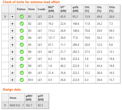
The bolts are not heavily loaded according to manual calculation. The same case is in IDEA. The bolts at the column flange to seat angle are B7–B10. The bearing and the shear capacity are calculated according to AS 4100 so the resistances are nearly the same as according to B. Kirke, I.H. Al-Jamel.
Rotational stiffness
The rotational stiffness of this joint is very low and is classified as pinned.
Conclusion
The manual calculation recognizes the buckling capacity of the beam web as a decisive failure mode with Vb = 179.2 kN. IDEA StatiCa allows slightly higher load capacity, 192 kN before the plates reach 5% limit strain. The difference is 7 % and it is caused by neglecting the stabilizing effect of the upper angle on the buckling of the web in manual assessment.


