
Bearing stiffeners (AISC)
This verification example was prepared by Mark D. Denavit, Rick Mulholland, and Javad Esmaeelpour in a joint project of The University of Tennessee and IDEA StatiCa.
Description
A comparison between results from the component-based finite element method (CBFEM) and traditional calculation methods used in US practice for bearing stiffeners is presented in this study. The study focuses on limit states specifically associated with bearing stiffeners. The first case investigated is bearing stiffeners in transfer girders, where a column bears on the top flange, inducing a single-concentrated compressive force. The second case investigated is bearing stiffeners in beam-to-column moment connections. These stiffeners are often called continuity plates. Moment in the beam results in tensile and compressive forces (i.e., double-concentrated forces) on the flange of the column. Comparisons to experimental results are also performed.
Traditional calculations are performed in accordance with the provisions for load and resistance factor design (LRFD) in the AISC Specification (2022). The CBFEM results were obtained from IDEA StatiCa version 24.0. The maximum permitted loads were determined iteratively by adjusting the applied load input to a value that the program deems safe but if increased by a small amount (1 kip) the program would deem unsafe by exceeding the 5% plastic strain limit, exceeding 100% bolt or weld utilization, or with a buckling ratio less than 3.0. DR type analyses can help identify maximum permitted loads. However, some approximation is made in the evaluation of the joint design resistance, therefore all results in this report are based on EPS type analysis.
Requirements for Bearing Stiffeners in the AISC Specification
AISC Specification Section J10 describes five potential limit states for I-shaped members with single-concentrated loads on the flange.
- Flange Local Bending
- Web Local Yielding
- Web Local Crippling
- Web Sidesway Buckling
- Web Compression Buckling
A stiffener is required if the required strength exceeds the available strength for any of these limit states. The available strength from these limit states is also used to determine the required strength for the stiffeners.
Once the need for stiffeners is established, the stiffener is designed in accordance with the requirements of AISC Specification Section J10.8.
Interior stiffeners (i.e., those away from the member end) subject to compressive forces are designed as axially compressed members in accordance with AISC Specification Sections E6.2 and J4.4, with a cross-section, shown in Figure 1, composed of the stiffeners and a strip of the web with a width of 25tw, and an effective length of Lc = 0.75h, where tw is the web thickness and h is the height of the stiffener. Limit states associated with this effective column section are yielding and flexural buckling. According to AISC Specification Section J4.4, yielding applies when Lc/r ≤ 25 and flexural buckling applies otherwise. Additionally, the limit state of bearing between the stiffener and the member flange is checked according to AISC Specification Section J7.
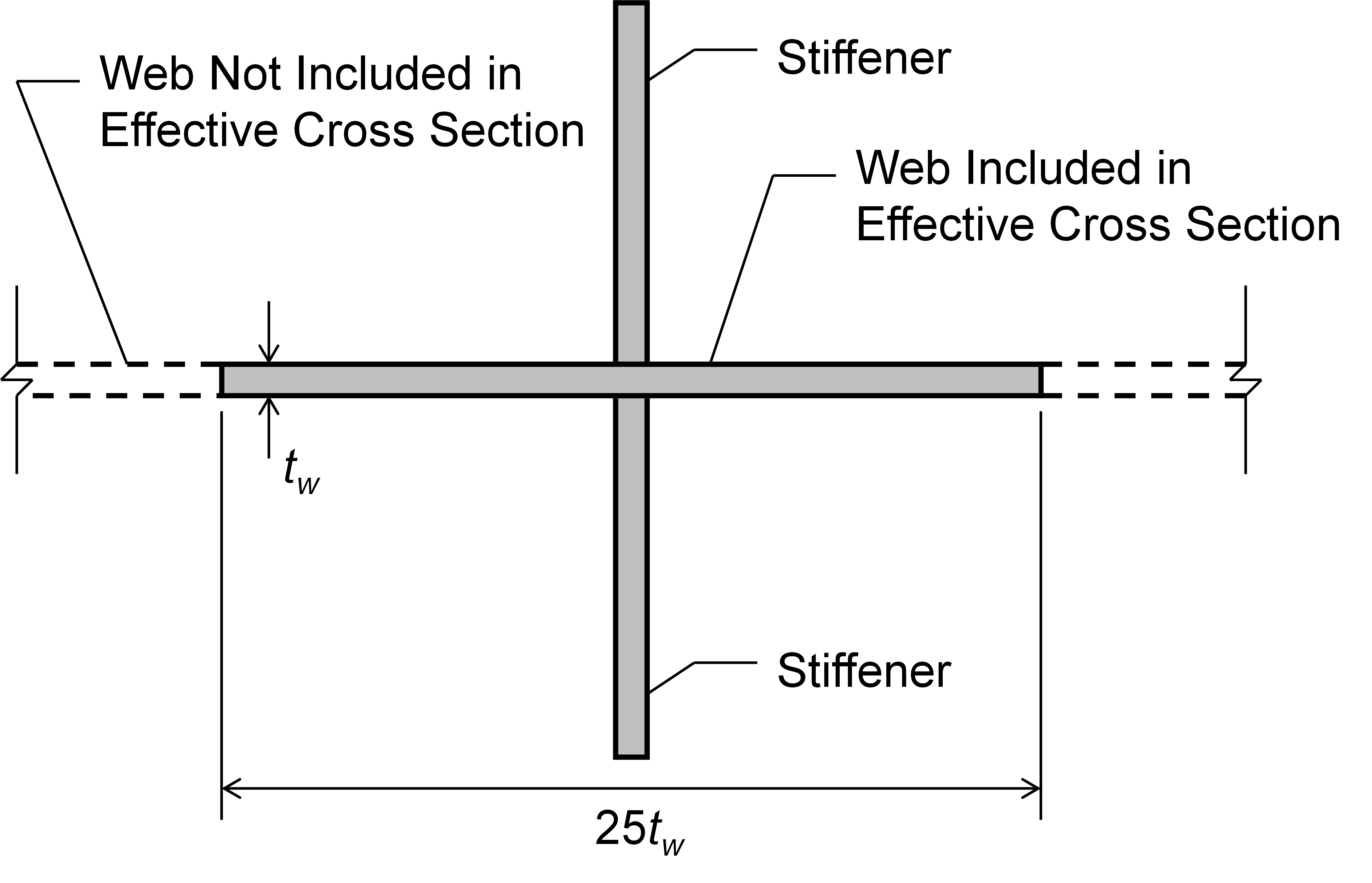
Figure 1 Effective cross-section defined in AISC Specification J10.8 for interior stiffeners.
Stiffeners subject to tensile concentrated forces are designed according to AISC Specification Section J4.1 with a required strength equal to difference between the applied load and the available strength for the controlling concentrated load limit state on the unstiffened section.
AISC Specification Section J10.8 has additional dimensional requirements for transverse stiffeners as follows:
- The width of each stiffener plus one-half the thickness of the column web shall not be less than one-third of the flange or moment connection plate width delivering the concentrated force.
- The thickness of a stiffener shall not be less than one-half the thickness of the flange or moment connection plate delivering the concentrated load, nor less than the width divided by 16
- Transverse stiffeners shall extend a minimum of one-half the depth of the member except as required in Sections J10.3, J10.5 and J10.7.
AISC Specification Section J10.3 requires stiffeners to extend a minimum of three-quarters of the depth of the web when stiffeners are required because the unstiffened member has insufficient strength for the web local crippling limit state. Section J10.5 requires stiffeners to extend the full depth of the web when stiffeners are required because the unstiffened member has insufficient strength for the web compression buckling limit state. Section J10.7 pertains to unframed ends of beams and girders and does not apply to this study.
Bearing Stiffeners in Transfer Girders
When a column is supported by a transfer girder, the concentrated force on the girder often exceeds the local strength of the girder, making it necessary to install transverse bearing stiffeners. The strength of bearing stiffeners in transfer girders is evaluated in this section with respect to variations in the following parameters:
- Stiffener thickness
- Stiffener width
- Weld length along the girder web
- Applied moment
For these comparisons, the girder is a W40x149. To isolate the controlling limit states to those associated with the girder web and stiffener, the column framing to the top flange was selected to be a strong I-shaped member with a total depth of 12 in., flange width of 8 in, and flange and web thickness of 2 in. Both the girder and column conform to ASTM A992 (Fy = 50 ksi and Fu = 65 ksi). The column sits atop a base plate that is 9 in. x 13.5 in. x 1 in. and conforms to ASTM A572 Gr 50 (Fy = 50 ksi and Fu = 65 ksi). The base plate is welded to the top flange of the transfer girder (a contact operation was also defined between the base plate and the top flange in IDEA StatiCa). The girder is stiffened with a double-sided stiffener (i.e., a stiffener on each side of the girder web) positioned concentrically beneath the column base plate. To avoid web shear buckling modes, 3/4 in. thick transverse stiffeners were added 24 in. away from centerline of the column and the default length of standard member was set to 0.5 in the code setup. A three-dimensional view of the connection is presented in Figure 2.
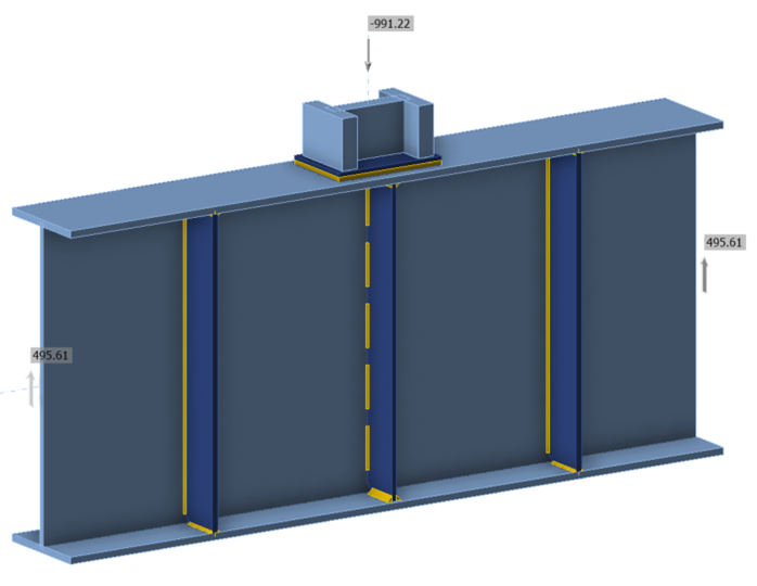
Figure 2 Three-dimensional view of transfer girder connection
Effect of Stiffener Thickness
To evaluate the effect of stiffener thickness, connections with stiffeners of varying thickness were investigated. The stiffeners were 5 in. wide, spanned the full depth of the girder web, and had 1.0 in. corner clips at the top and bottom. The stiffeners were welded to the girder web using 1/4 in. double-sided fillet welds, 5 in. long spaced 2 in. apart, and welded to the top and bottom flanges using continuous 5/8 in. double-sided fillet welds (a contact operation was also defined between the stiffeners and flanges in IDEA StatiCa).
For the traditional calculations, the limit states of yielding and flexural buckling were evaluated for the effective column, bearing was evaluated on the stiffener-to-flange contact surface, and rupture was evaluated on the welds between the stiffeners and the girder web. The required strength for the stiffener-to-web welds was taken as the difference between the applied force and the smaller of the available strength for the limit states of web local yielding and web local crippling on the unstiffened girder.
Calculations were performed on 9 stiffener thicknesses ranging from 1/2 in. to 1 in. in 1/16 in. increments. The maximum factored compressive force that can be applied to the column according to IDEA StatiCa and the traditional calculations is presented in Figure 3. IDEA StatiCa results are shown for the default mesh settings (maximal size of element = 1.969 in.) and a refined mesh where the maximal size of element is set to 0.75 in.
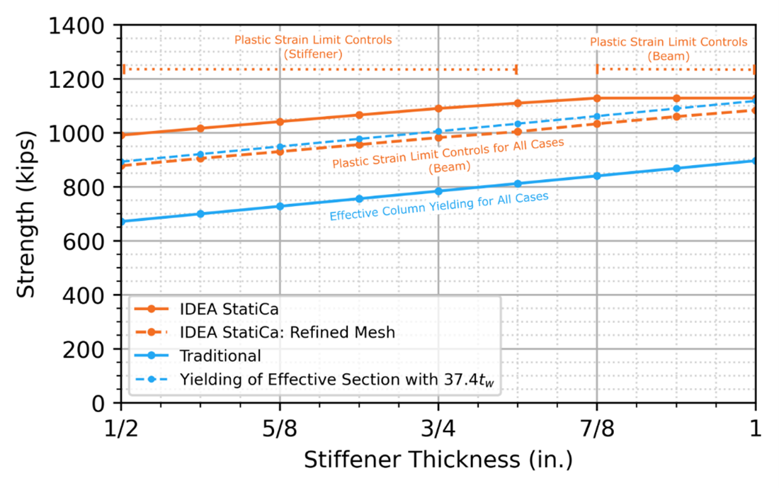
Figure 3 Strength vs stiffener thickness for transfer girder connection (bearing stiffener subject to single-concentrated compressive force)
For the traditional calculations, yielding of the effective cruciform section controlled for all thicknesses tested. As a result, the strength increases linearly with stiffener thickness. The IDEA StatiCa strength, controlled by the plastic strain limit, is greater than that from the traditional calculations. The equivalent stress and plastic strain distributions for the connection with the 3/4 in. thick stiffener are presented in Figure 4. The traditional calculations use an effective cruciform cross-section where only a 25tw width of the web is considered (Figure 1). For the W40x149 girder used in this example, tw = 0.630 in. and 25tw = 15.75 in. AISC Specification Section J10.2 assumes for the web local yielding limit state that the load is distributed over a length of the web equal to the length of bearing plus 5 times the distance from outer face of the flange to the web toe of the fillet. Following this assumption with length of bearing equal to the length of the base plate (13.5 in.) and the properties of the W40x149 (k = 2.01 in.), the length of web that is engaged for the web local yielding limit state is equal to 23.55 in. or 37.4tw. Figure 3 shows the results of an alternative traditional calculation of the yielding on an effective cruciform cross-section with a web width of 37.4tw instead of 25tw. The strength from the alternative traditional calculations is similar to that from IDEA StatiCa using the refined mesh.
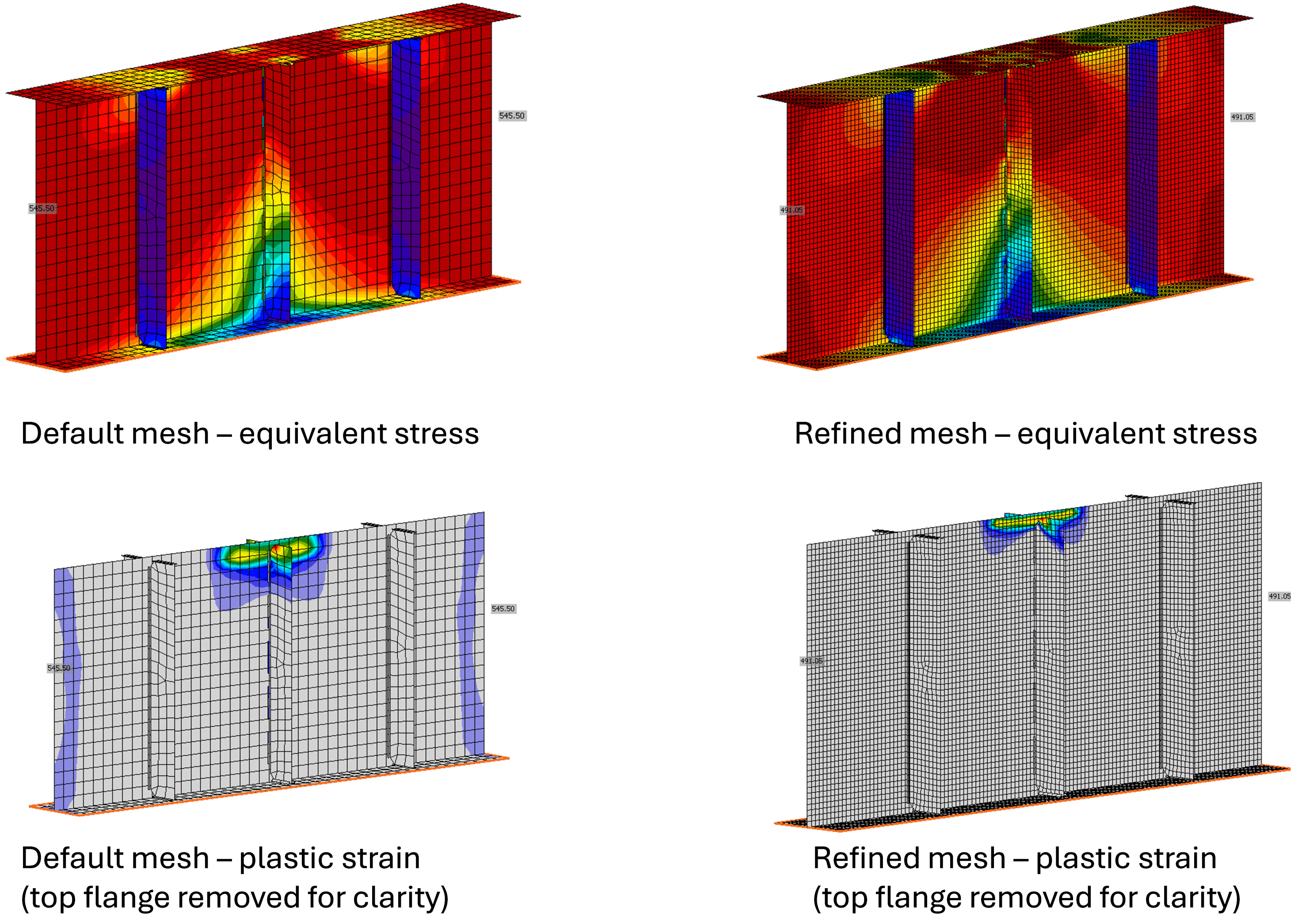
Figure 4 Equivalent stress and plastic strain distributions for transfer girder connection with 3/4 in. thick stiffeners. Applied load = 1091.0 kips (default mesh); 982.1 kips (refined mesh)
Effect of Stiffener Width
To evaluate the effect of stiffener width, a 3/4 in. thick double-sided stiffener was chosen, and 15 different stiffener widths were tested ranging from 2 in. to 5.5 in., in 1/4 in. increments. Note that some of the smaller stiffener widths do not satisfy the dimensional requirements of AISC Specification Section J10.8(a). A comparison of strength vs stiffener width is presented in Figure 5.
As expected, the strength of the connection increases with increased stiffener width for both the traditional calculations and IDEA StatiCa analysis. The IDEA StatiCa strength is greater than the strength by traditional calculations. As before, the use of an effective cross section in the traditional calculations that only includes a 25tw width of the web is part of the reason for the difference. Use of a more refined mesh in IDEA StatiCa is also expected to reduce the difference in strength.
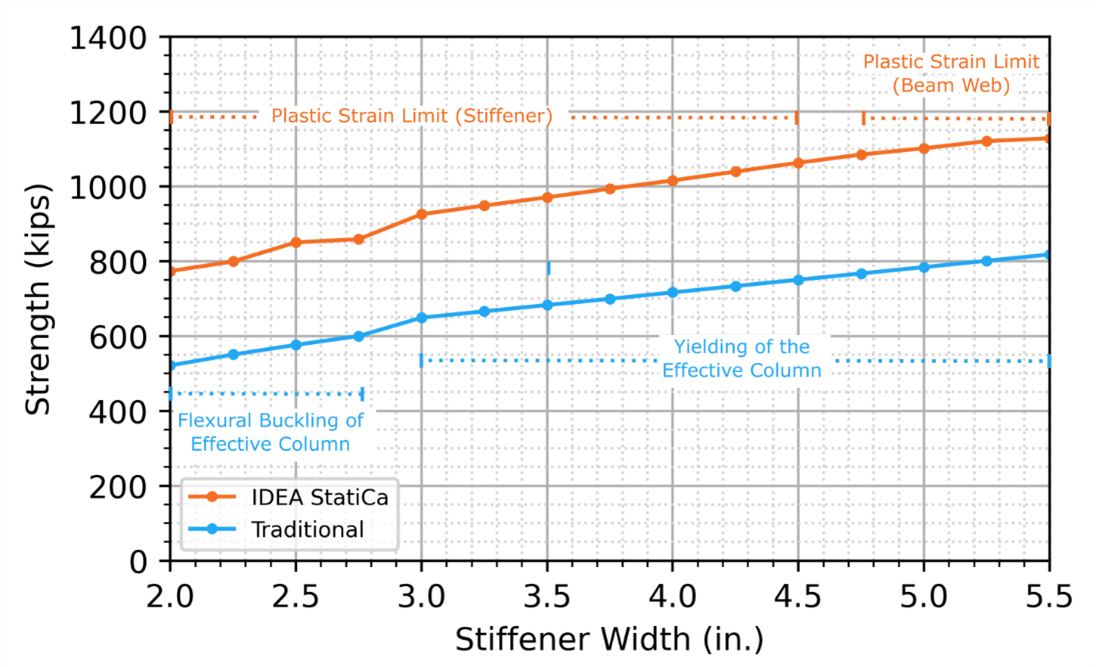
Figure 5 Strength vs stiffener width for transfer girder connection (bearing stiffener subject to single-concentrated compressive force)
Effect of Weld Length
In the traditional calculations, the weld between the stiffener and girder web is sized for a required strength equal to the difference between the applied load and the lower of the available strengths for the limit states of web local yielding and web local crippling (computed assuming the stiffener is not present).
To evaluate the effect of weld length along the girder web, 5-1/2 in. wide and 3/4 in. thick stiffeners are welded to the top and bottom flanges using 1/4 in. double-sided fillet welds. The stiffeners are welded to the web using 1/4 in. intermittent double-sided fillet welds. The total weld length is the combined weld length between the web and the stiffeners for each side of each stiffener (i.e., 4 times the length of the weld on one side of one stiffener). A continuous weld would have a total length of 138 in. The connections described previously to evaluate the effect of stiffener thickness and width had a total length of 100 in.
Eleven total weld lengths ranging from 20 in. to 100 in., with increments of 8 in., were tested. Intermittent welds were used with 4 evenly spaced lengths of weld on each side of each stiffener. The weld started and ended 2 in. from stiffener's chamfered corners. A comparison of strength versus weld length is presented in Figure 6.
The IDEA StatiCa strength is greater than that for the traditional calculations, as observed previously in Figure 3 and Figure 5. As the total weld length decreases and weld strength controls for both IDEA StatiCa and the traditional calculations, the strength results become closer. Some differences in strength are expected since, in the traditional calculations, the required strength for the weld is equal to the difference between the applied force and the smaller of the available strength for the limit states of web local yielding and web local crippling. Previous investigations have shown the strength from IDEA StatiCa for web local yielding and web local crippling can be greater than that from the traditional calculations, but generally consistent with results from advanced finite element simulations.
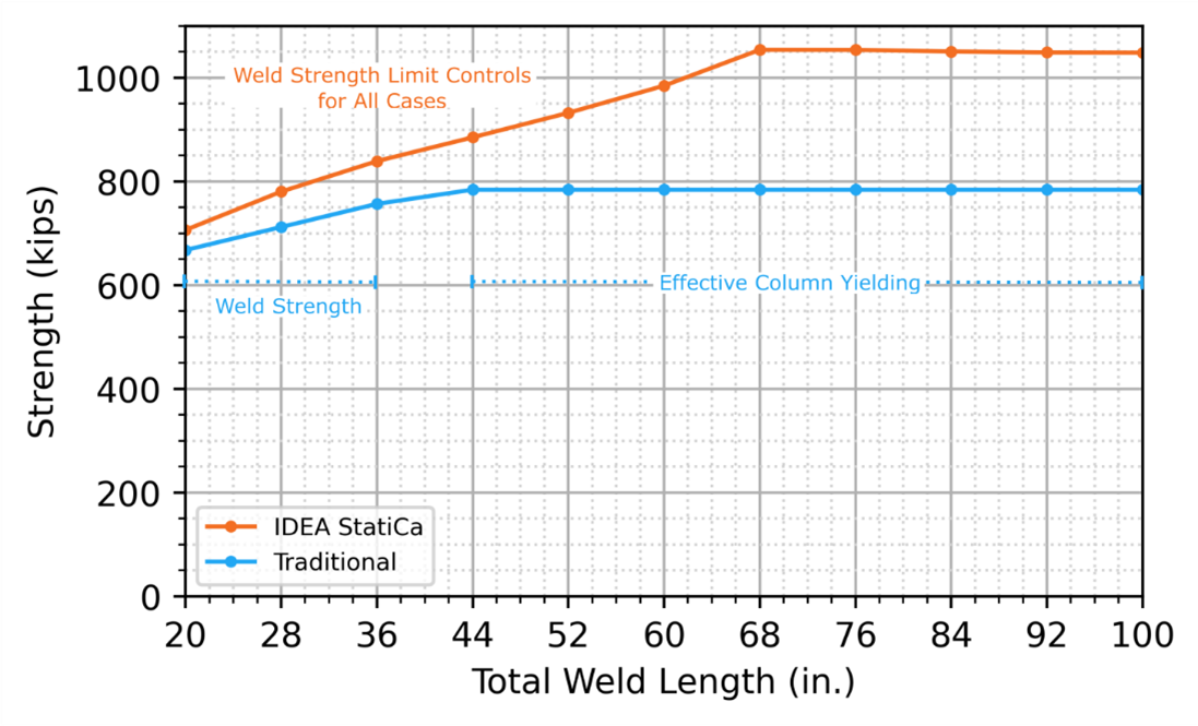
Figure 6 Strength vs weld length for transfer girder connection (bearing stiffener subject to single-concentrated compressive force)
Effect of Applied Moment
The connections in all the previous analyses were loaded in IDEA StatiCa such that there was no moment in the girder at the centerline of the column. The magnitude of moment at the location of a point load in a transfer girder will depend on factors such as girder span and end conditions. The magnitude of moment in the girder does not affect the traditional calculations but can affect the IDEA StatiCa results. To investigate the effect of applied moment on strength, analyses were performed with applied moment. The magnitude of the moment, normalized as M/ϕMp, (where ϕ = 0.9 and Mp is the plastic moment, ϕMp = 2,242 kip-ft for the W40x149 girder) was varied between 0.0 and 1.0 in increments of 0.1. Only positive bending moment (i.e., moment inducing longitudinal compression in the top flange) was applied. Connections with full-depth stiffeners with width of 5 in. and thicknesses of 0.5 in. and 0.75 in. were investigated and the results are presented in Figure 7.
The strength from IDEA StatiCa is nearly constant for applied moments up to approximately 70% of ϕMp, above which a gradual decline in strength was observed. While the applied moment has little impact on the strength for this case, other connections and loading configurations may behave differently. In general, all loads applied to a connection should be considered in the IDEA StatiCa model.
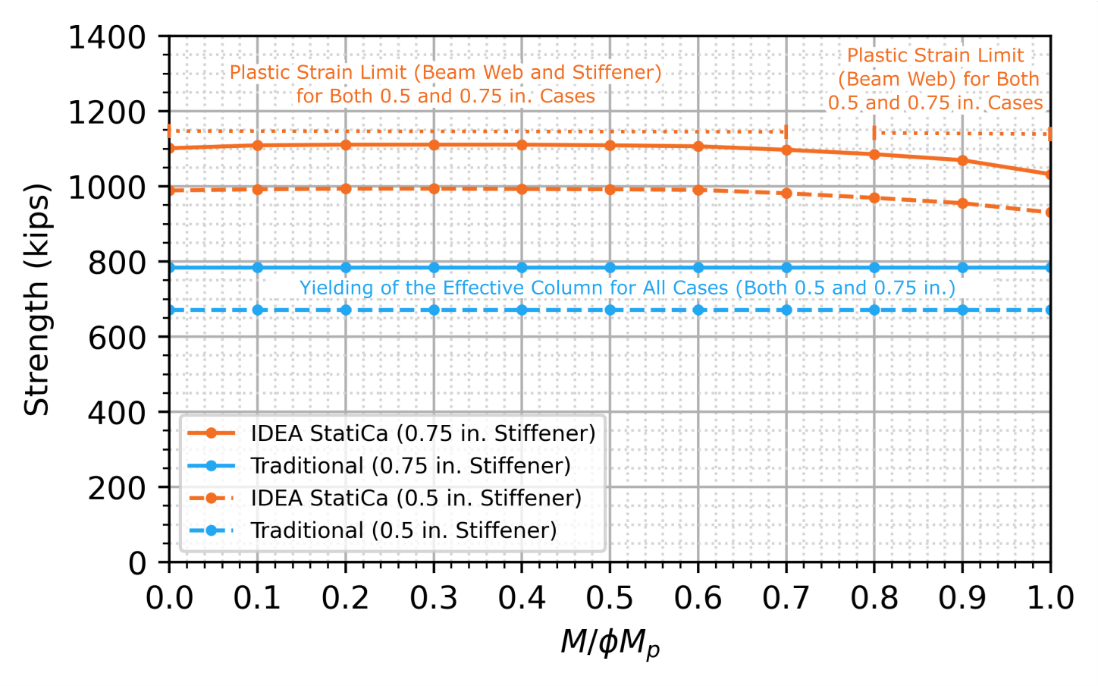
Figure 7 Strength vs applied moment for transfer girder connection (bearing stiffener subject to single-concentrated compressive force, ϕMp = 2,242 kip-ft)
Bearing Stiffeners in Beam-to-Column Moment Connections
Double-concentrated forces arise at beam-to-column connections where the moment in the beam applies a force couple to the column flange. Columns subjected to a double-concentrated force often require stiffeners which are also called continuity plates. This study investigates the case of a single-sided beam-to-column moment connection and specifically the variation of strength with stiffener plate thickness.
The configuration of the connection in this comparison matches that of AISC Design Guide 13 Examples 6-1 through 6-3 (Carter 1999). The beam is a W18x50, and the column is a W14x53, both conforming to ASTM A992 (Fy = 50 ksi and Fu = 65 ksi). Often in moment connections, a web doubler plate is needed to achieve sufficient web panel zone shear strength. However, in this example, to eliminate the need for a doubler plate and focus investigation on the stiffener (continuity) plate, the thickness of the web of the W14x53 column was modified to 9/16 in. Additionally, a simplified connection between the beam and column was employed whereby the beam flanges are welded to the column flange using complete joint penetration welds, and the beam web is connected to the column flange using a single-sided plate (ASTM A572 Gr 50) welded to the beam web and column flange using 1/2 in. fillet welds.
The stiffeners are 3 in. x 10.5 in. plates with 3/4 in. corner clips and conform to ASTM A36 (Fy = 36 ksi and Fu = 58 ksi). The stiffeners are welded to the column web and beam-side flange using double-sided fillet welds of size 1/4 in. and 1/2 in., respectively. A three-dimensional view of the connection is presented in Figure 8.
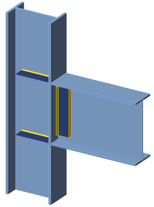
Figure 8 Three-dimensional view of single-sided moment connection
In this example, 14 stiffener thicknesses ranging from 3/16 in. to 1 in. are examined. Stiffeners with thicknesses of 3/16 in. and 1/4 in. do not meet the dimensional requirements of AISC Specification Section J10.8, specifically that the stiffener thickness shall not be less than one-half the thickness of the beam flange but were included in the investigations for comparison. An axial compressive load of 300 kips was applied to the column (P/AgFy = 0.48), and the maximum permitted applied moment was determined. A plot of the maximum permitted applied moment (i.e., the strength) vs stiffener thickness is presented in Figure 9. The annotations in Figure 9 identify the controlling limit for each case. In the traditional calculations, the equations for panel zone strength for “when the effect of inelastic panel-zone deformation on frame stability is not accounted for in the analysis” were used.
Where the panel zone shear strength controls, the strengths from the traditional calculations and those from IDEA StatiCa are similar. For the thinner stiffeners, where yielding of the stiffeners controls, the strength from IDEA StatiCa is greater than that from the traditional calculations with IDEA StatiCa showing only minor reductions in strength and the traditional calculations showing greater reductions in strength as stiffener thickness decreases.
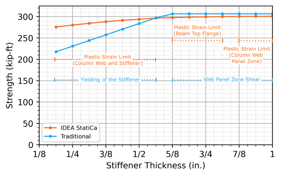
Figure 9 Strength vs stiffener thickness for single-sided moment connection
Comparison to Experimental Results
The comparisons presented in this study have shown that the strength of connections with bearing stiffeners according to IDEA StatiCa often exceeds that of the traditional calculations. The differences can, in part, be explained by conservatism in the AISC Specification provisions (e.g., use of an effective cross-section with only a 25tw width of web included). To expand on the investigation, this section includes comparisons to previously published experimental results.
For these comparisons, the dimensions and material yield stress were taken as measured and reported by the experimentalists and resistance factors were not applied. For IDEA StatiCa, the resistance factors for material and welds were set to 1.0 in the code setup.
Stiffeners in Compression – Bougoffa et al. 2021 and 2022
Bougoffa et al. (2021) investigated the strength of stiffeners in the compression zone of beam-to-column connections. Eight specimens without stiffeners and sixteen with transverse stiffeners were tested under patch loading applied through plates on both sides spanning the entire width of the flanges. A schematic of the testing configuration is presented in Figure 10.
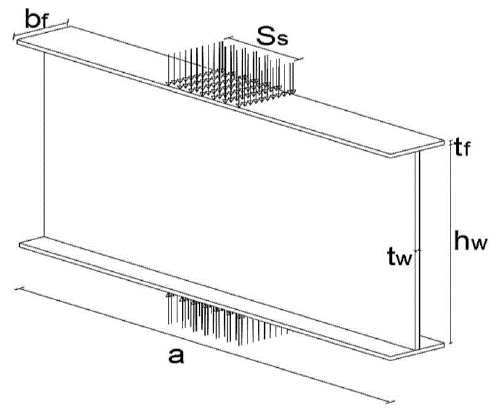
Figure 10 Web panel under opposite patch loading (Bougoffa et al. 2021)
Of the sixteen stiffened specimens tested, four were unstiffened (denoted as group US), four were double-sided full depth (DFS), two were single-sided full depth (SFS), two were partial depth single-sided (PTSE), two were single-sided partially stiffened on the central part of the web (PTSC), and two were single-sided partially stiffened with a less than half-depth stiffener at each flange. The DFS, SFS and PTSE type specimens were selected for comparison to IDEA StatiCa analysis, as these arrangements have bearing stiffeners that are representative of those commonly used in practice. The results of the comparison are presented in Table 1 and Figure 11.
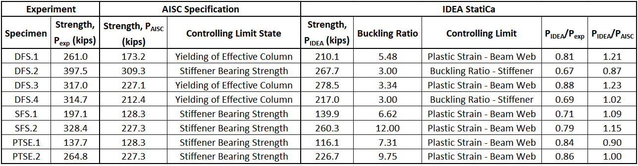
Table 1 Comparison to the Bougoffa et al. (2021) experimental investigation
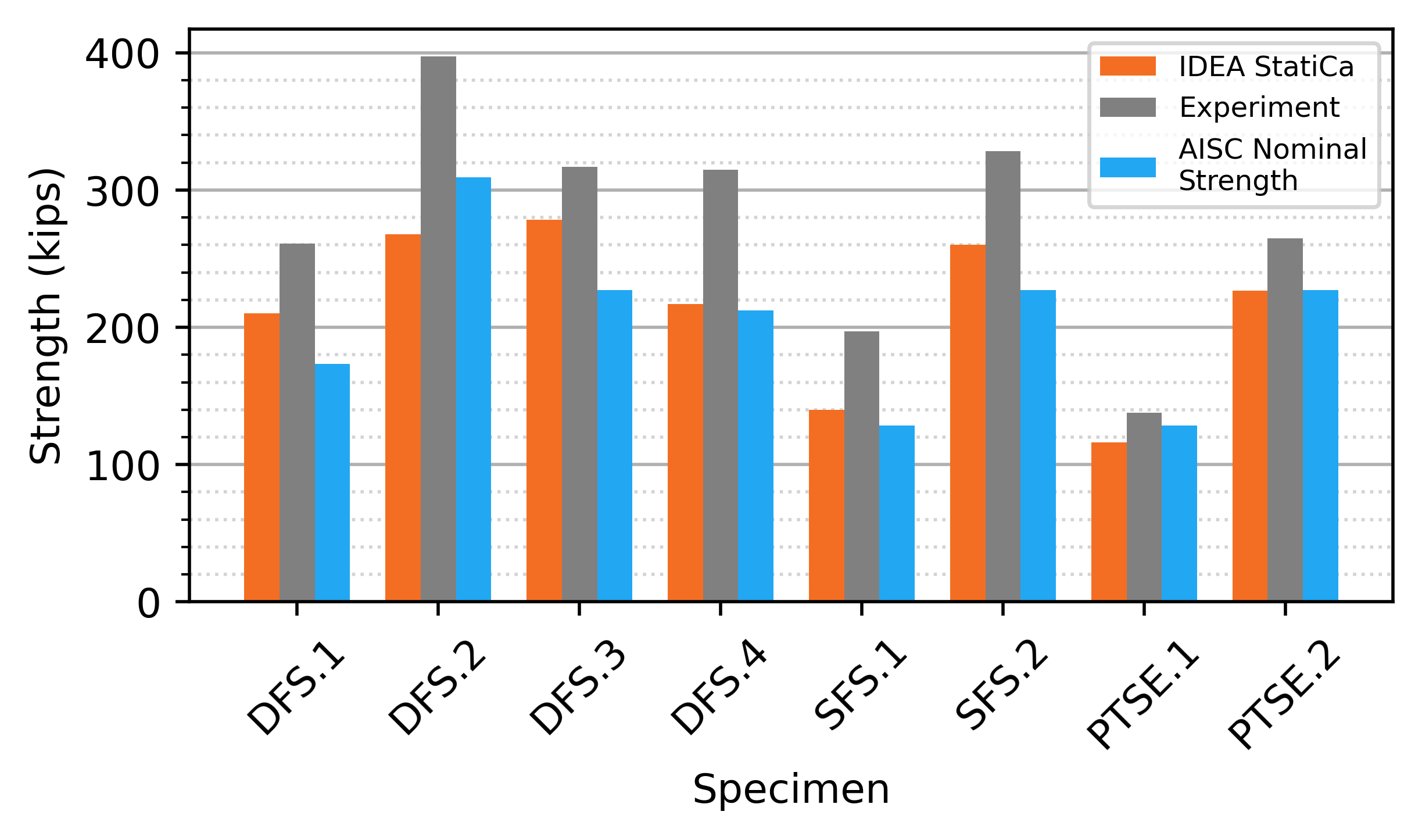
Figure 11 Comparison to the Bougoffa et al. (2021) experimental investigation
The IDEA StatiCa analysis is conservative in comparison to the experimental results. Plastic strain in the beam web controlled for most of the specimens. The buckling ratio limit controlled for specimens DFS.2 and DFS.4. Buckling of the stiffener was observed in the experimental investigation for the DFS type specimens. A comparison between the buckled shape from IDEA StatiCa for DFS.1 and that of the physical specimen is presented in Figure 12.
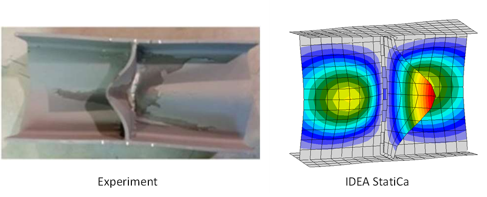
Figure 12 Buckled shapes of specimen DFS.1 (Bougoffa et al., 2021)
Bougoffa et al. (2022) performed additional experiments on unstiffened and stiffened I-shaped sections in double compression. Tests were performed on panels of a welded I-shaped section with 3 stiffening configurations: unstiffened panel (P0S 508 and P0S 370), panel with intermediate stiffener (PMS 508 and PMS 370), and panel with edge stiffener (PES 508 and PES 370). The specimens with 508 in their name had a web height of 488 mm. The specimens with 370 in their name had a web height of 349 mm. For all specimens, the thickness of the web was 6 mm, the width of the flange was 200 mm, and the thickness of the flange was 10 mm. Additional dimensions and the loading configurations for the specimens are presented in Figure 13.
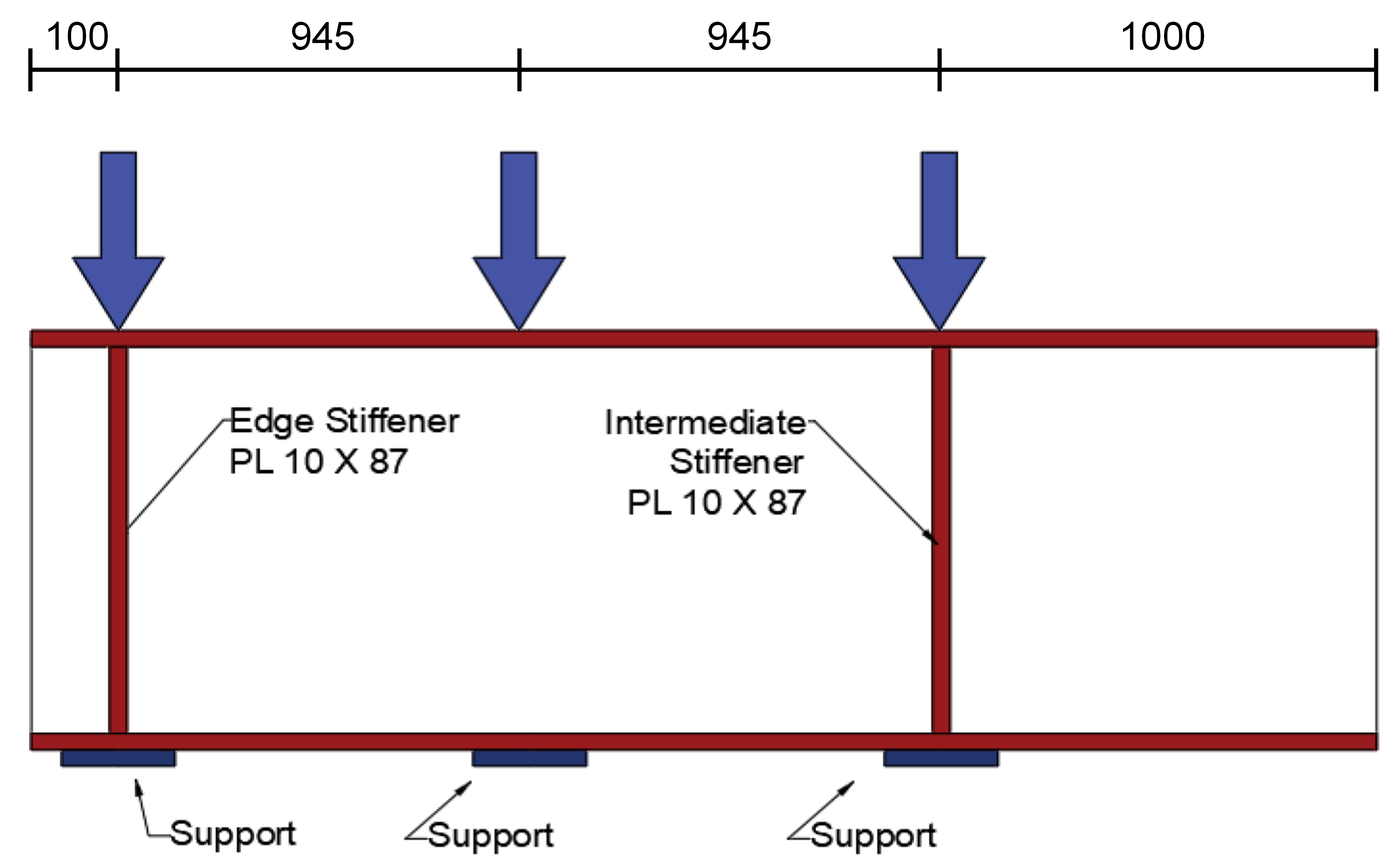
Figure 13 Loading configuration, dimensions in mm (Bougoffa et al., 2022)
The average peak load for 4 tests of each configuration was reported. The average values were compared to analyses in IDEA StatiCa. Measured material properties were not reported in the original article but obtained from the corresponding author (Bouchair 2023). The beam flanges and stiffeners had a yield stress of 51.9 ksi, and the webs had a yield stress of 52.2 ksi. For the IDEA StatiCa model, the web yield stress of 52.2 ksi was used for both the web and flange of the I-section. Results of the comparison are presented in Table 2 and Figure 14.
The 5% plastic strain limit controlled for specimen PMS 370, and the 3.0 buckling ratio limit controlled for all other specimens. The strength from IDEA StatiCa is greater than that from the AISC Specification for 4 of the 6 specimens, but less than that from the experiment in all 6 cases.
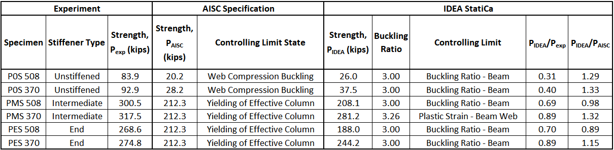
Table 2 Comparison to the Bougoffa et al. (2022) experimental investigation
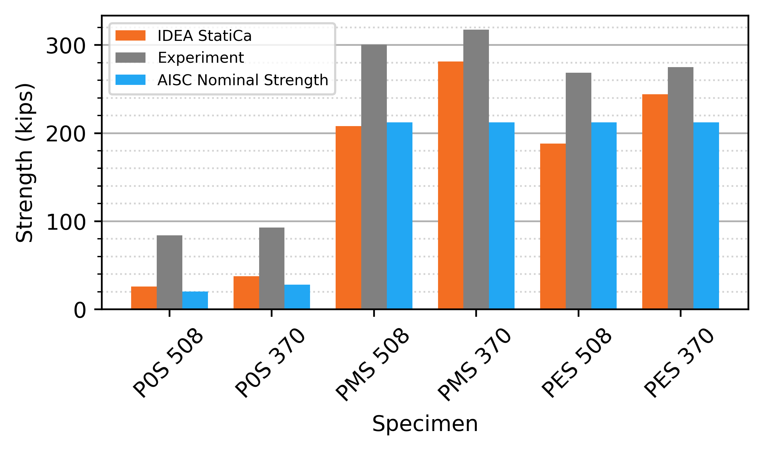
Figure 14 Comparison to the Bougoffa et al. (2022) experimental investigation
Partial Depth Stiffeners – Salkar et al. 2015
Salkar et al. (2015) performed tests on 27 specimens divided into 3 groups, however, measured material properties (e.g., yield stress) were only reported for the 17 specimens in group 3. Of the group 3 specimens, 5 were loaded using a patch plate, 11 were loaded using a roller, and 1 was loaded with an I-section bearing on the top flange. The experiments are also described by Salkar (1992).
The beam for all specimens was a W16x26 loaded in three-point bending. Shear and moment were applied to the beam in IDEA StatiCa to replicate the moment diagram in the experiment. The roller was modeled in IDEA StatiCa as a 1/2 in. wide rectangular plate. The stiffeners at midspan, which extend either one half or three quarters the depth of the beam, were welded to the beam web and top flange using 1/4 in. welds. In IDEA StatiCa, in addition to the weld, a contact operation was defined between the stiffener and top flange of the beam. The patch plate testing configuration and details of the group 3 tests, as presented by Salkar et al. (2015), are replicated in Figure 15 and Table 3, respectively. Stiffeners at the supports were modeled with an assumed thickness of 1/4 in.
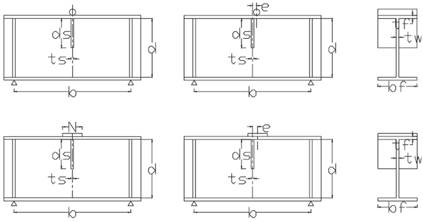
Figure 15 Roller and patch plate loading configurations, Salkar et al. (2015)
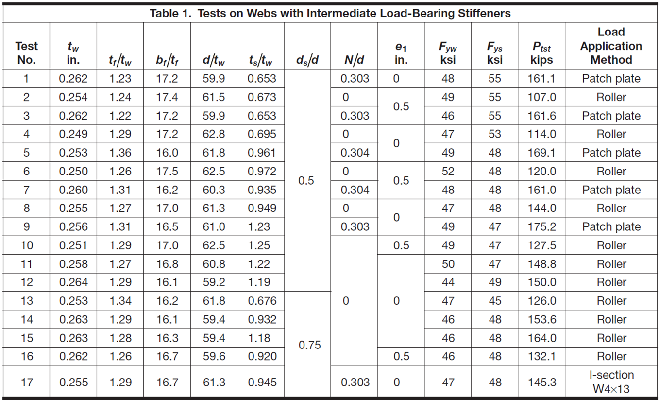
Table 3 Group 3 test details, Salkar et al. (2015)
The configurations of the test specimens and corresponding yield stresses shown in Table 3 were modeled in IDEA StatiCa. The results of the comparison are presented in Table 4 and Figure 16. The buckling ratio limit controlled for specimens loaded with the patch plate or I-section (a comparison of buckled shapes for specimen 9 is presented in Figure 17) while plastic strain in the beam web controlled for all but one of the specimens loaded with a roller. On average, the strength from IDEA StatiCa results is 5% less than the experimental strength.
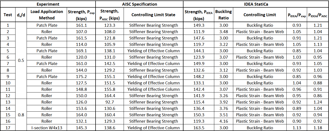
Table 4 Comparison to the Salkar et al. (2015) experimental investigation
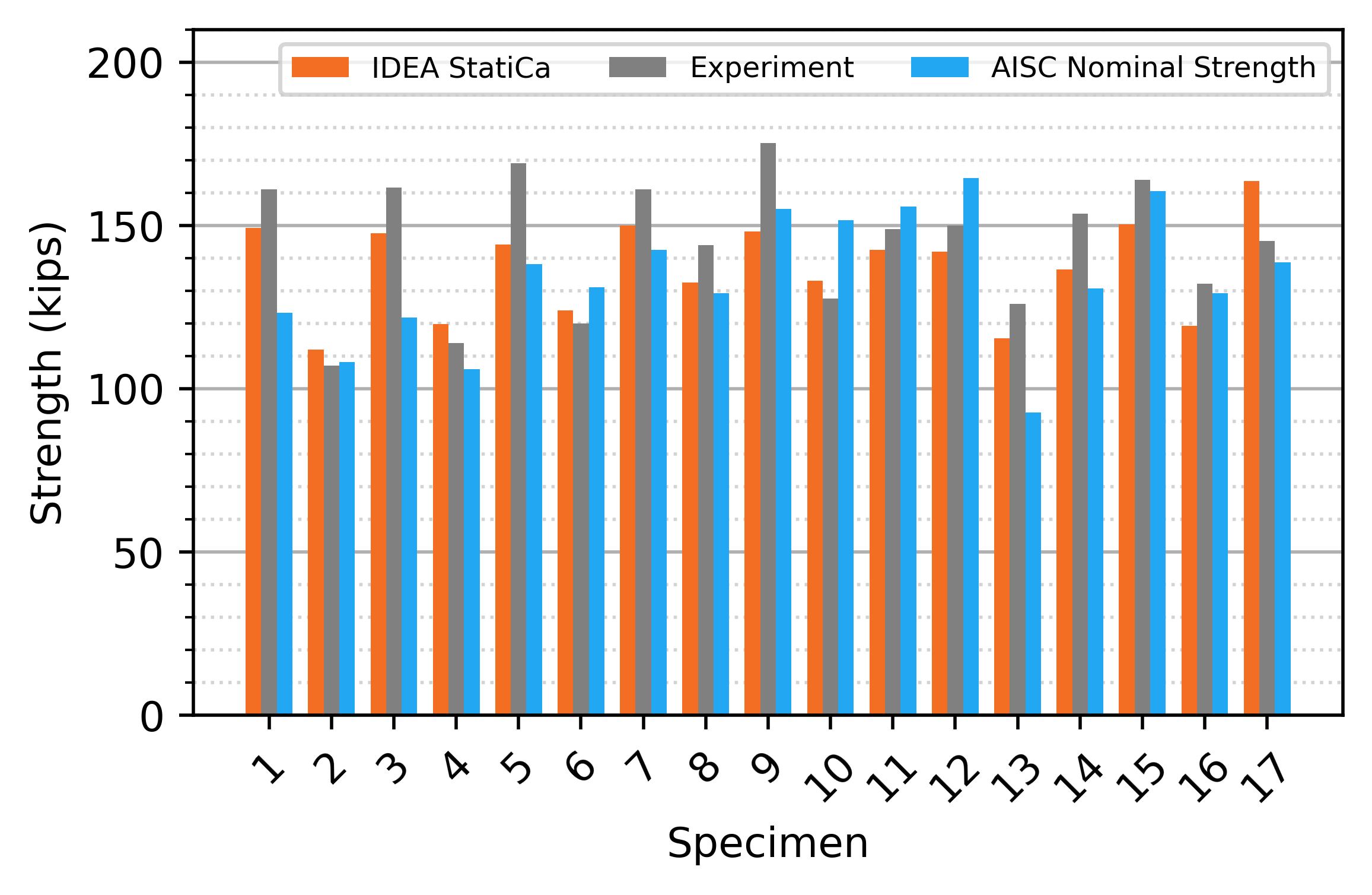
Figure 16 Comparison to the Salkar et al. (2015) experimental investigation
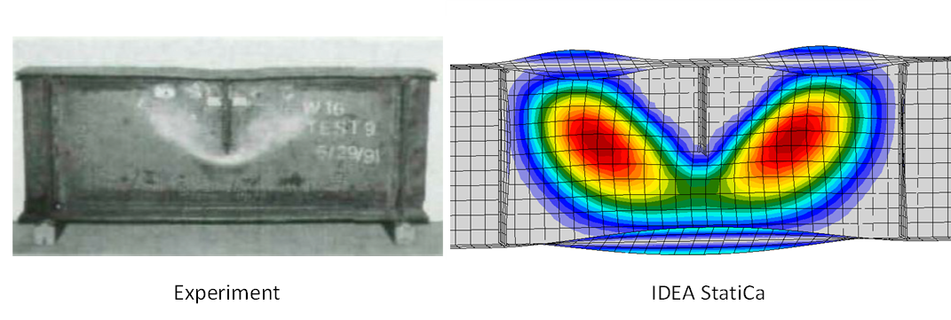
Figure 17 Buckled shapes of specimen 9 (Salkar et al., 2015)
Eccentric Stiffeners – Graham et al. 1959
Graham et al. (1959) investigated the effect of stiffener eccentricity. Tests were performed on 12WF40 and 14WF61 column stubs, with the specimens compressed transverse to the longitudinal axis between bars until failure. The effect of stiffeners with eccentricities of 0, 2, 4, and 6 in. was evaluated. The study showed a decline in the stiffener effectiveness for eccentricities greater than 2 in. and concludes, “For design purposes it would probably be advisable to neglect the resistance of stiffeners having eccentricities greater than 2 in.”. This recommendation was incorporated in AISC Design Guide 13 (Carter 1999).
The test specimens from the study, shown in Table 5, were modeled in IDEA StatiCa, and the results were compared to those from the study. The IDEA StatiCa model matches the testing configuration, with a wide flange member compressed between two 3/4 in. x 7/16 in. x 7 in. bars. The wide flange member conforms to ASTM A36, but measured material properties were not reported so nominal values of Fy = 36 ksi and Fu = 58 ksi were used in the analysis. The bars were modeled with Fy = 100 ksi and Fu = 110 ksi to isolate the controlling limit states to that associated with the test specimen. The stiffener spans the full depth of the web, has dimensions of 1/4 in. x 3-3/4 in., and conforms to ASTM A36. The stiffener was welded to the flanges and web using complete joint penetration welds in IDEA StatiCa to eliminate any failure modes associated with the welds. A three-dimensional view of the 12WF40 specimen with stiffener eccentricity of 2 in. is presented in Figure 18.
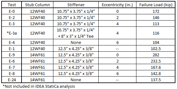
Table 5 Program of tests with eccentric stiffeners, Graham et al., 1959
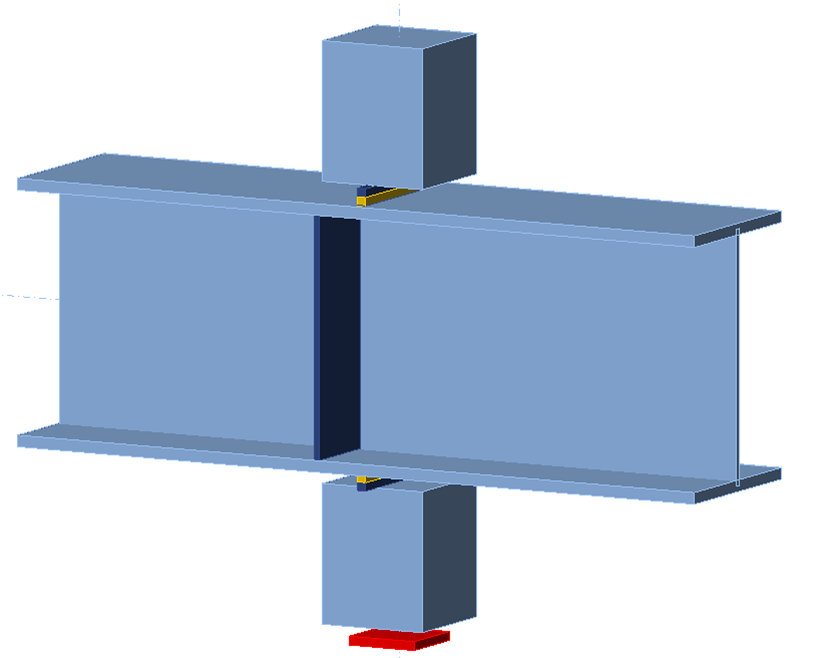
Figure 18 Three-dimensional view of 12WF40 specimen modeled in IDEA StatiCa (stiffener eccentricity = 2-in.)
The relationship between strength and stiffener eccentricity is presented for the 12WF40 and 14WF61 specimens in Figure 19 and Figure 20, respectively. Since measured material properties were not reported, a direct comparison of values between experimental results and IDEA StatiCa results is not possible. However, the trends from IDEA StatiCa analyses are similar to those from the experimental results. As expected, the connection is strongest with a concentric stiffener and the strength decreases with increasing eccentricity.
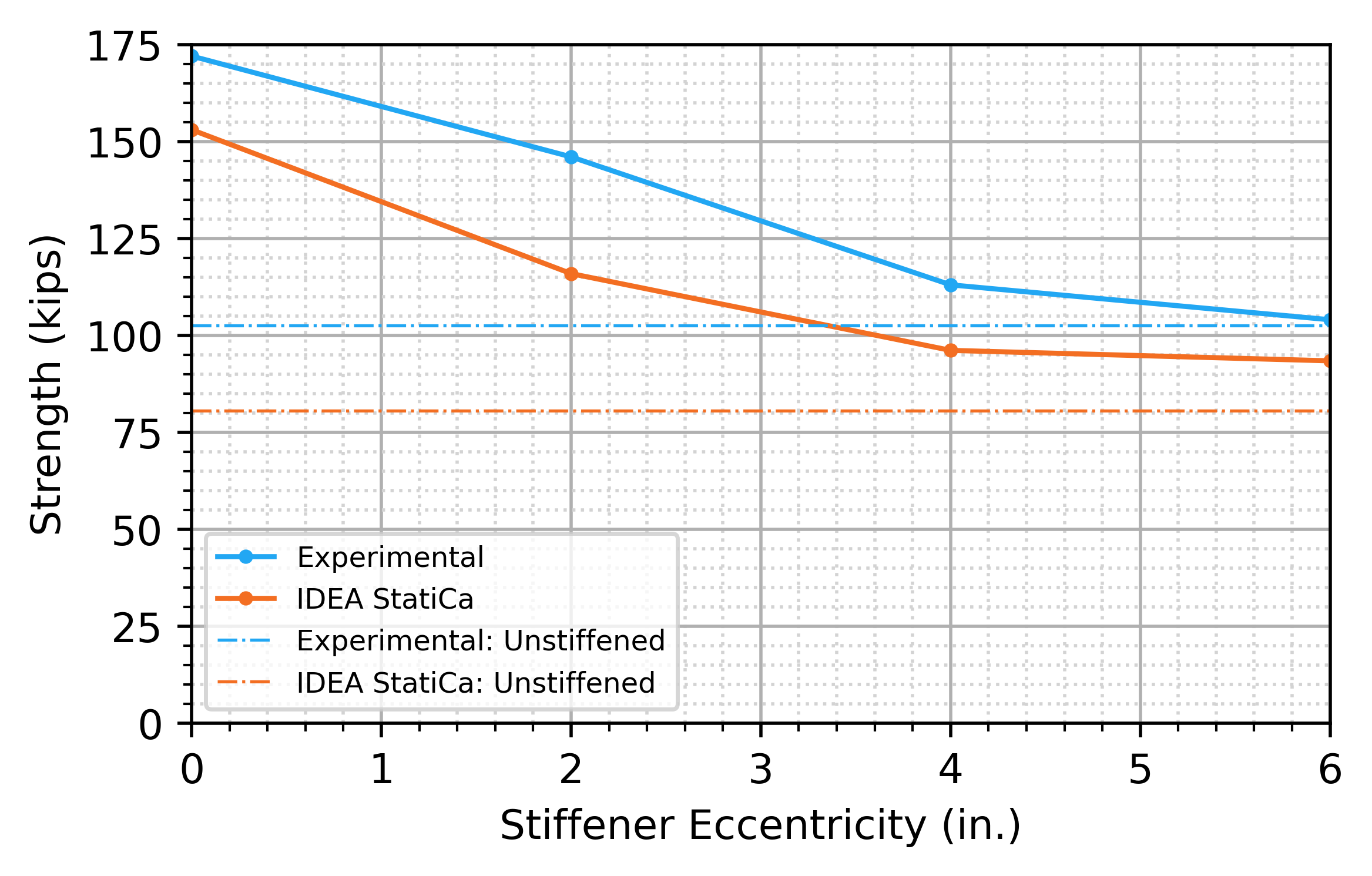
Figure 19 Strength vs stiffener eccentricity (12WF40)
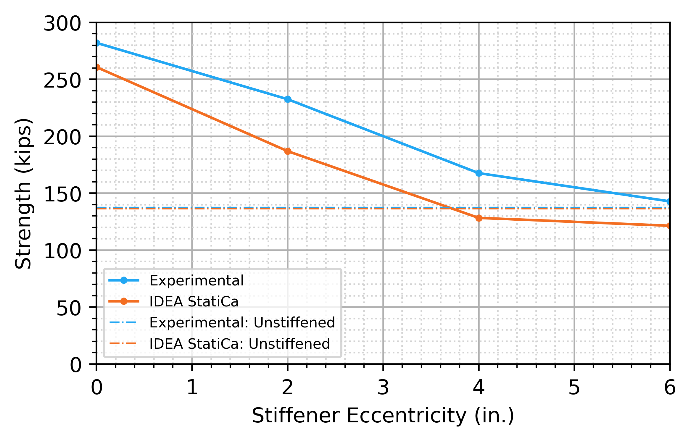
Figure 20 Strength vs stiffener eccentricity (14WF61)
Eccentric Stiffeners – Alvarez Rodilla and Kowalkowski 2021
Alvarez Rodilla and Kowalkowski (2021) also investigated the effect of stiffener eccentricity. They performed tests on segments of columns with forces on the flange. The tests were performed under three loading conditions: single compression (with W16x31, W12x26, W10x39, and W10x19 columns), double compression (with W16x31, W12x26, and W10x19 columns), and single tension. For each loading condition and column size, four specimens were tested: 1) without stiffeners, 2) with concentric stiffeners (no eccentricity), 3) with stiffeners at a lower eccentricity (2 in. or 3 in.), and 4) with stiffeners at a higher eccentricity (4 in. or 6 in.). The single tension specimens are not investigated in this study given the focus of this study on compressive forces and that the strength of many of the single tension specimens was not achieved due to limitations of the test equipment. Specimen W12×26 DC-E0 was also excluded from this study since its experimental strength was not achieved due to limitations of the test equipment.
The column specimens were 6 ft long and fabricated from ASTM A992 steel (the measured yield stress is listed in Table 6).
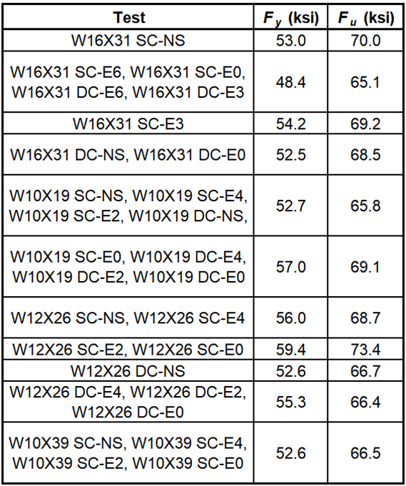
Table 6 Measured yield stress of wide flange shapes, Alvarez Rodilla and Kowalkowski (2021)
For the W10×39, W12×26, and W16×31 column specimens, the stiffeners were 3/8 in. thick and welded using 1/4 in. fillet welds. For the W10×19 column specimens, the stiffeners were 1/4 in. thick and welded using 3/16 in. fillet welds. For most specimens, the stiffeners were installed on both sides of the web; however, for the double compression tests with a W16X31 column, stiffeners were installed on only one side of the web. The stiffener plates were fabricated from A36 steel or dual certified A36 and A572 Gr. 50 steel. Specific measured material properties of the plate were not reported, Fy = 50 ksi was used for the calculations and analyses in this study. The stiffeners were full depth, extended to the flange tips, and had 1/2 in. corner clips.
The single compression specimens were simply supported with a span of 5 ft. Shear and moment were applied to the beam in IDEA StatiCa to replicate the moment diagram in the experiment. A three-dimensional view of specimen W12×26 SC-E4 is presented in Figure 18.
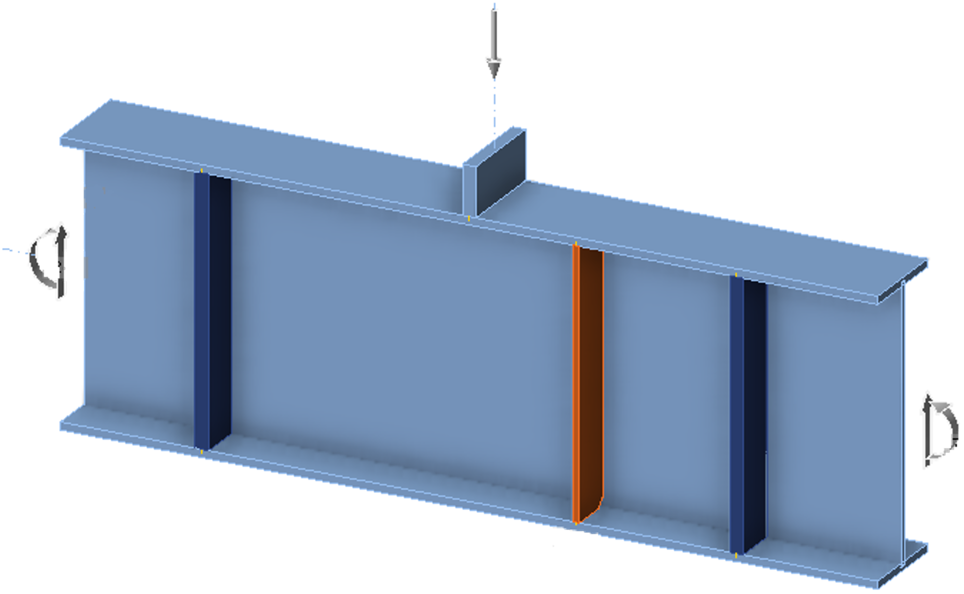
Figure 21 Three-dimensional view W12×26 SC-E4 specimen modeled in IDEA StatiCa.
The double compression specimens were tested in the same loading frame as the single compression specimens, but with the addition of a reaction plate on the bottom to produce the double compression force. However, the supports at the ends of specimen were still in place and resisted an unquantified portion of the applied load. The end supports were assumed to not be in place for this study.
A comparison between experimental, AISC Specification, and IDEA StatiCa strengths for the single and double compression specimens is shown in Table 7 and Table 8, respectively. The AISC Specification does not provide strength equations for eccentric stiffeners, so the strength from according to the AISC Specification for specimens with eccentric stiffeners is listed as “N/A”. Strength results are also presented in Figure 22 and Figure 23.
In general, the strength of the connection is highest with a concentric stiffener and decreases as eccentricity increases. This trend is observed experimentally and with the IDEA StatiCa results. The strength from IDEA StatiCa is lower than the experimental strength for all specimens. These results indicate that, while the strength benefit of eccentric stiffeners is small in comparison to that of concentric stiffeners, IDEA StatiCa provides a means of safely considering the contribution of eccentric stiffeners in design.
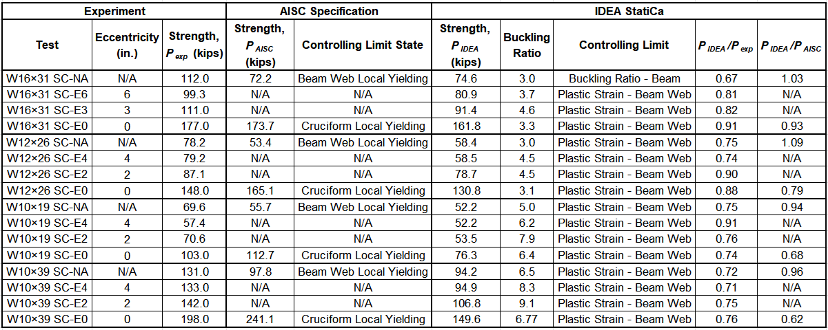
Table 7 Single Compression Theoretical Capacities and Test Results, Alvarez Rodilla and Kowalkowski., 2021.
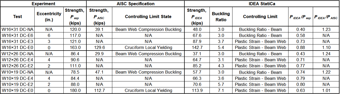
Table 8 Double Compression Theoretical Capacities and Test Results, Alvarez Rodilla and Kowalkowski., 2021.
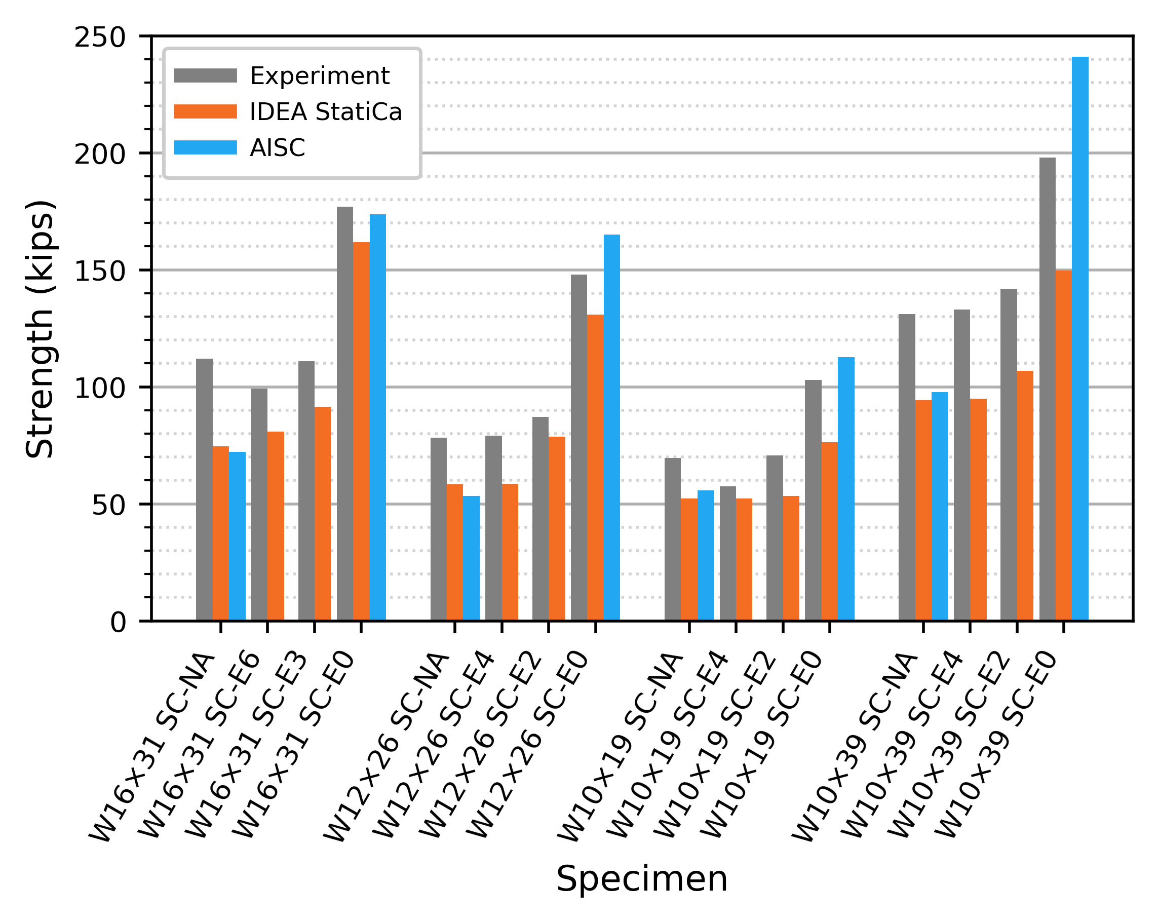
Figure 22 Comparison to the Alvarez Rodilla and Kowalkowski (2021) single compression experimental investigation
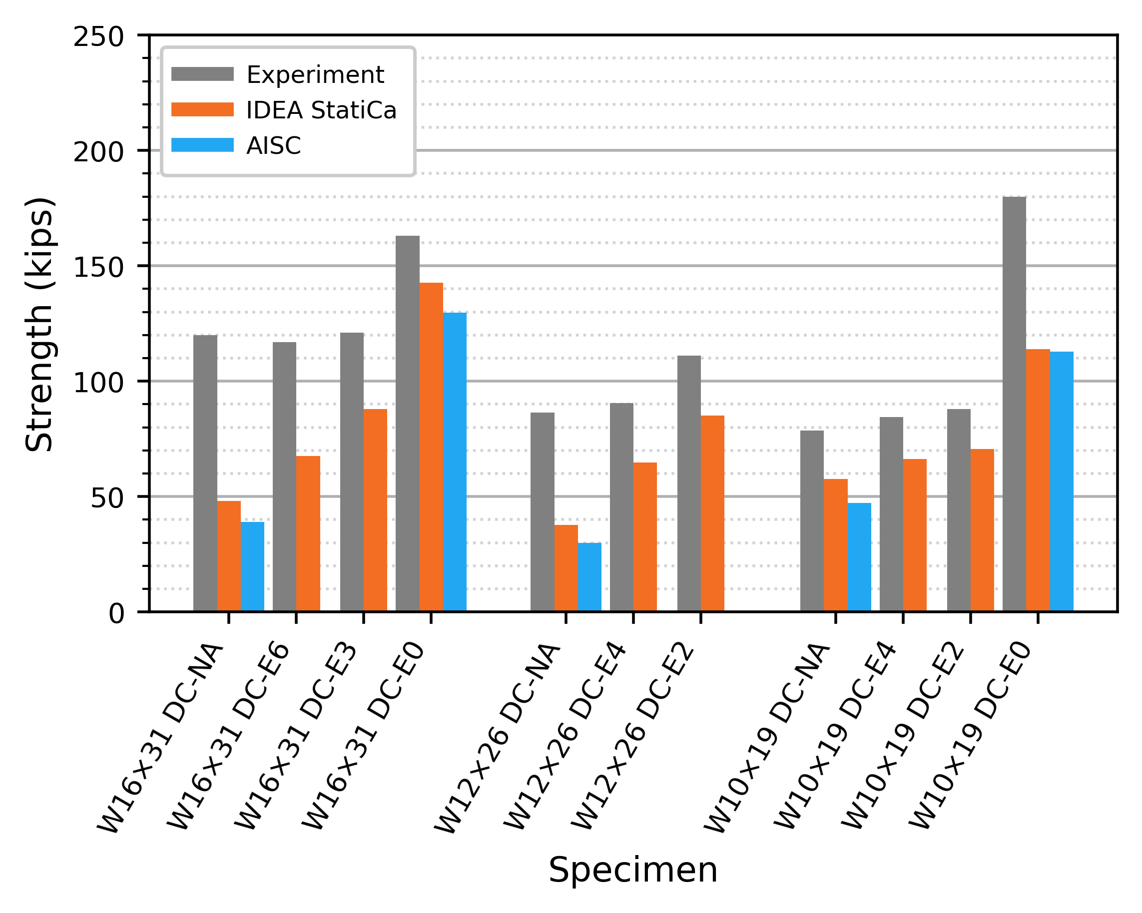
Figure 23 Comparison to the Alvarez Rodilla and Kowalkowski (2021) double compression experimental investigation
Summary
This study compared the design and evaluation of bearing stiffeners in structural steel connections by traditional calculation methods used in US practice and IDEA StatiCa. Key observations from the study include:
- The strength of connections with bearing stiffeners in IDEA StatiCa was found in several cases to be greater than the strength by traditional calculations.
- The differences are due, in part, to conservatism in the AISC Specification provisions, especially the dimensions of the effective cruciform section.
- In comparison to a range of physical experiments, strengths from IDEA StatiCa were found to be generally conservative with respect to measured strengths with only 5 of 58 specimens examined having IDEA StatiCa strength exceeded the experimental strength and by a maximum of 13%.
- Results in IDEA StatiCa are sensitive to refinement of the mesh with more refined meshes producing lower strengths.
- IDEA StatiCa allows explicit consideration of cases such as partial depth stiffeners and eccentric stiffeners, for which little guidance is provided in the AISC Specification.
References
AISC. (2022). Specification for Structural Steel Buildings. American Institute of Steel Construction, Chicago, Illinois.
Alvarez Rodilla, J., and Kowalkowski, K. (2021). “Determination of Capacities of Eccentric Stiffeners Part 1: Experimental Studies.” Engineering Journal, AISC, Second Quarter, 58, 79–98.
Bougoffa et al. (2021), “Experimental and Numerical Study of Compression Zone in Steel Connections”, ce/papers 4, Nos. 2-4, 850-856
Bougoffa et al. (2022), “Full Length Transverse Stiffener Under Compression”, ce/papers 5, No. 4, 967-973
Bouchair, AbdelHamid (2023), personal communication, May 26
Carter, C. J. (1999). Stiffening of Wide-Flange Columns at Moment Connections: Wind and Seismic Applications. Design Guide 13, American Institute of Steel Construction, Chicago, Illinois.
Graham, J. D.; Sherbourne, A. N.; Khabbaz, R. N.; and Jensen, C. D., (1959). "Welded interior beam-column connections”, AISC Publication, 1959, Reprint No. 146 (59-7, 60-3) (1959). Fritz Laboratory Reports. Paper 1568.
Salkar, R. (1992), “Strength and Behavior of Webs, With and Without Stiffeners, Under Local Compressive In-plane and Eccentric Loads”, University of Maine at Orno, Maine, Vol. 2, Chapter 5, 424-522.
Salkar et al. (2015), “Crippling of Webs with Partial-Depth Stiffeners under Patch Loading”, Engineering Journal, AISC, Fourth Quarter, 52, 221-232.