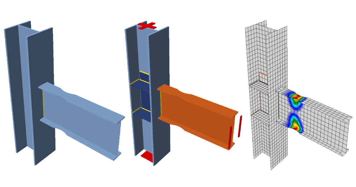
Steel connection capacity design (AISC)
1 New project
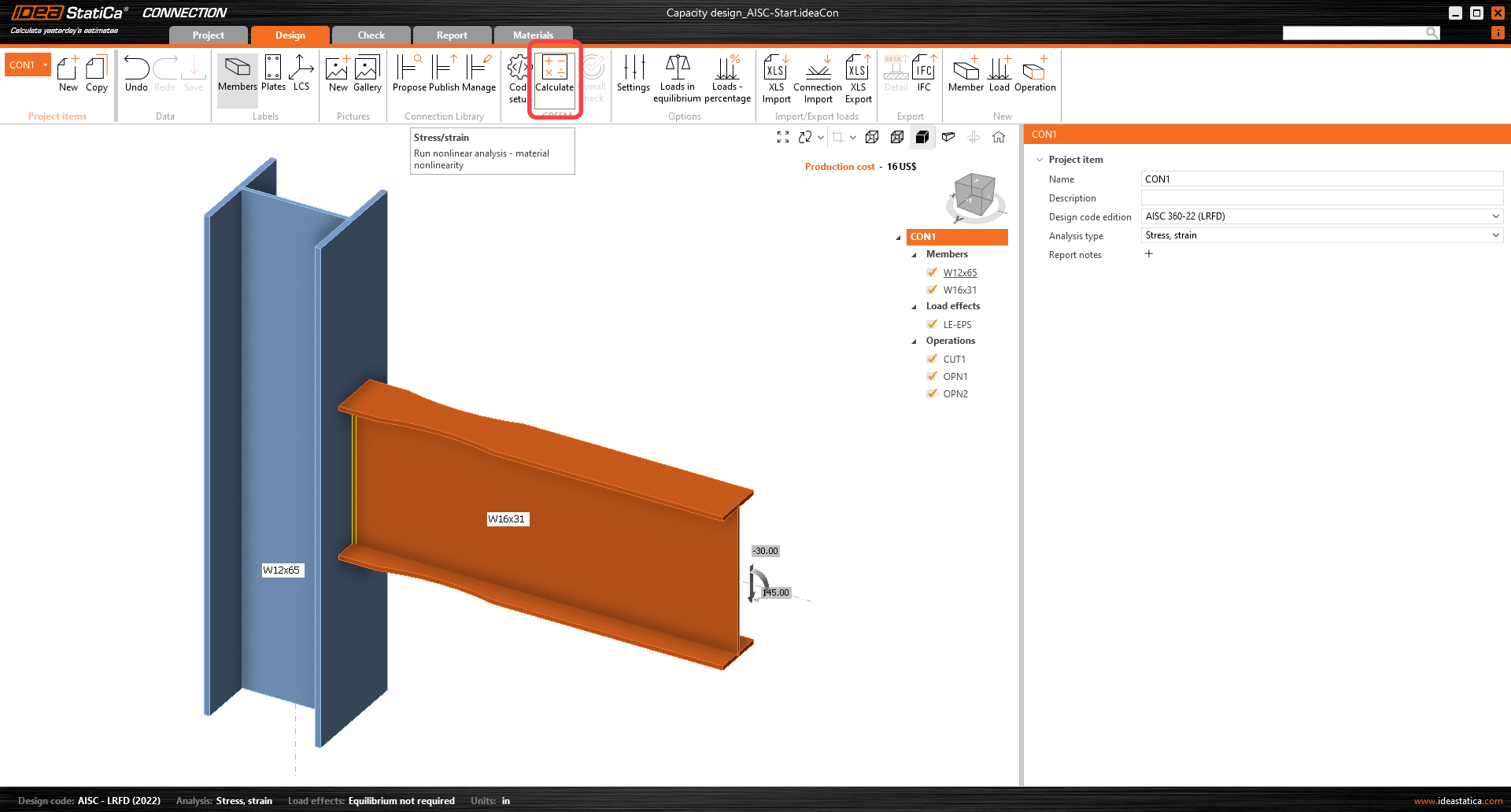
Launch IDEA StatiCa (download the newest version) and open the source project file. The joint design is finished and prepared for the standard Stress/Strain analysis.
2 Calculation and check
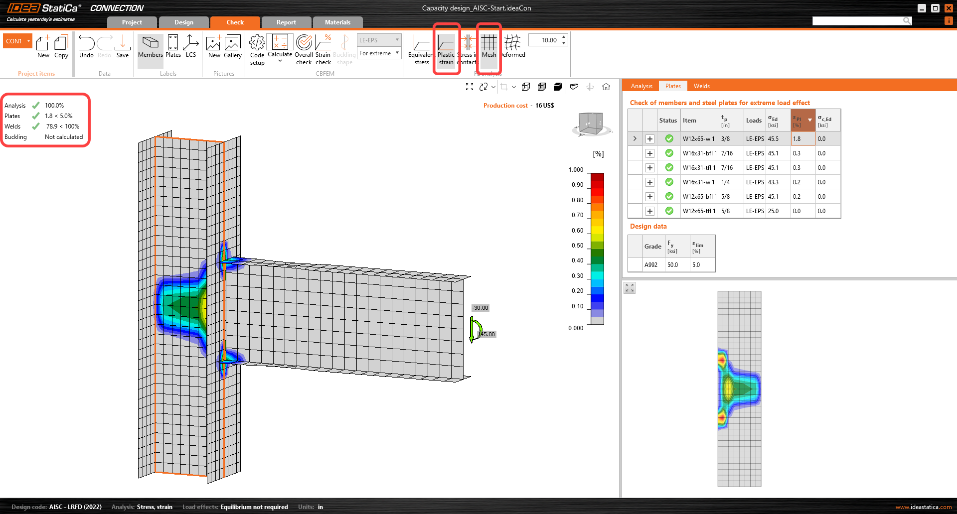
Start the stress/strain analysis by the Calculate button in the ribbon. The analysis model is automatically generated, the calculation is performed, and you can see the overall check results in the top left corner of the scene.
You can see that based on the stress/strain analysis, the joint is well-designed and passes all the checks.
To keep these results, copy this project item on the upper left corner under Project items.
3 Capacity check
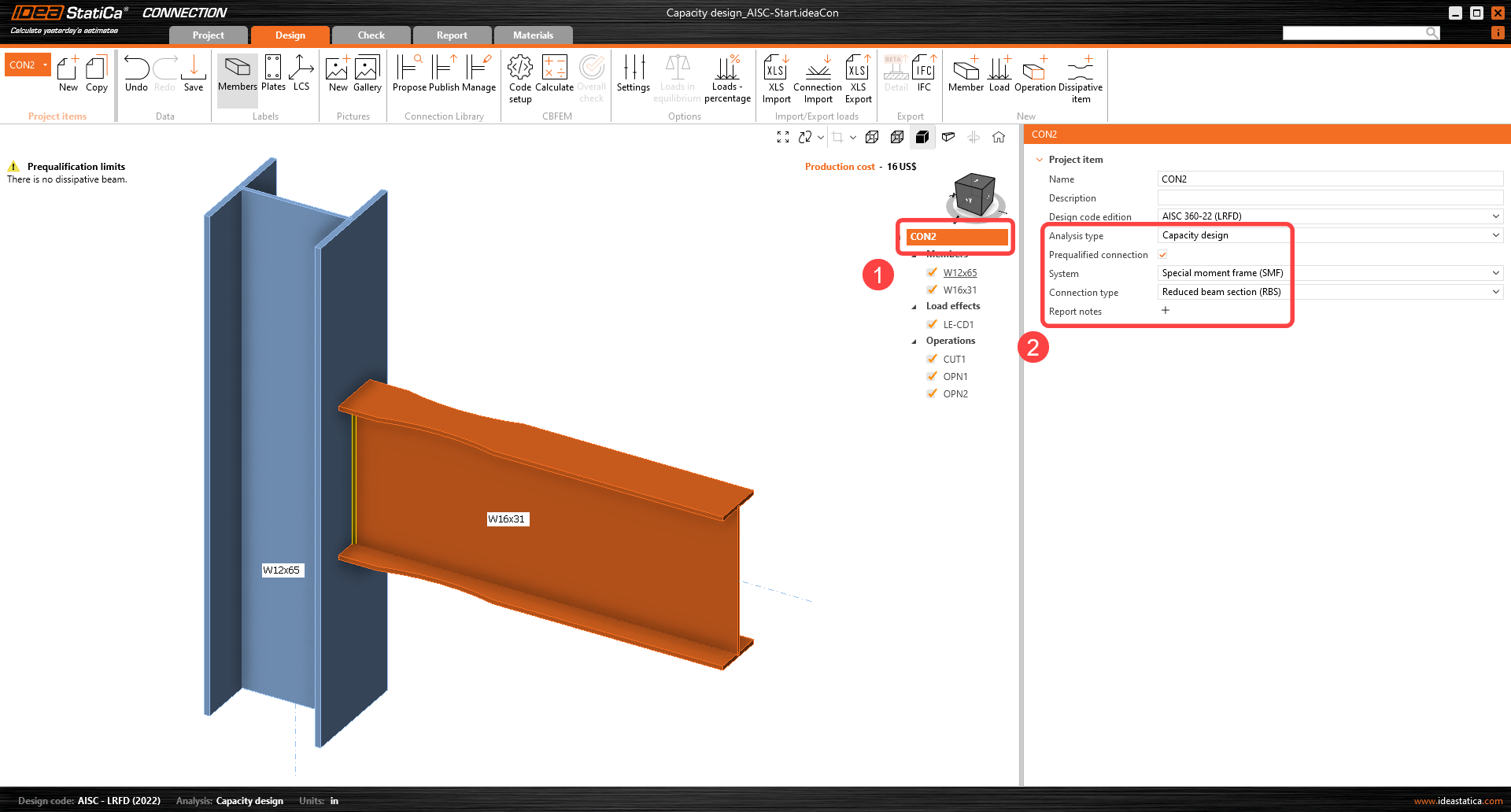
In the new project item (CON2), change the following inputs to enable the prequalification limit checks of AISC 358:
- Analysis type: Capacity Design
- Prequalified connection: Active
- System: Special moment frame
- Connection type: Reduced beam section (RBS)
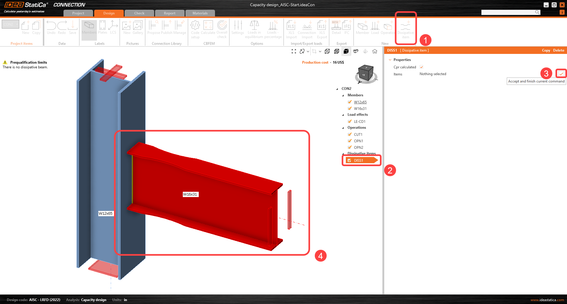
The dissipative item has to be selected. A member or a plate where a plastic hinge is expected to occur should be chosen as a dissipative item. The material overstrength factor and strain-hardening factor are applied to the chosen item. In this example, select the member W16x31 as the dissipative item. It can be added by the command from the top ribbon and confirm the selection with the spacebar/enter key/right-click.
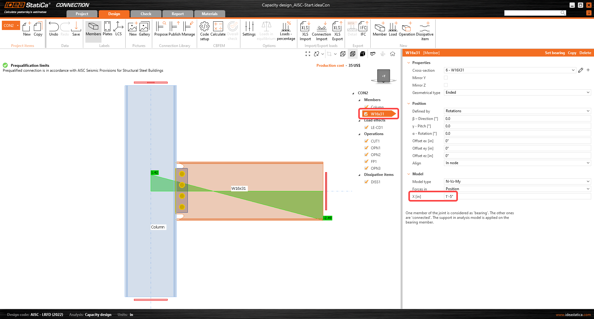
In the properties Members, the parameters of W16x31 must be adjusted: Set the Model type to N-Vz-My, because the connection resists the bending moment in the vertical plane only, and bending around the minor beam axis must be restrained.
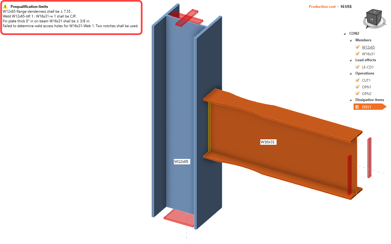
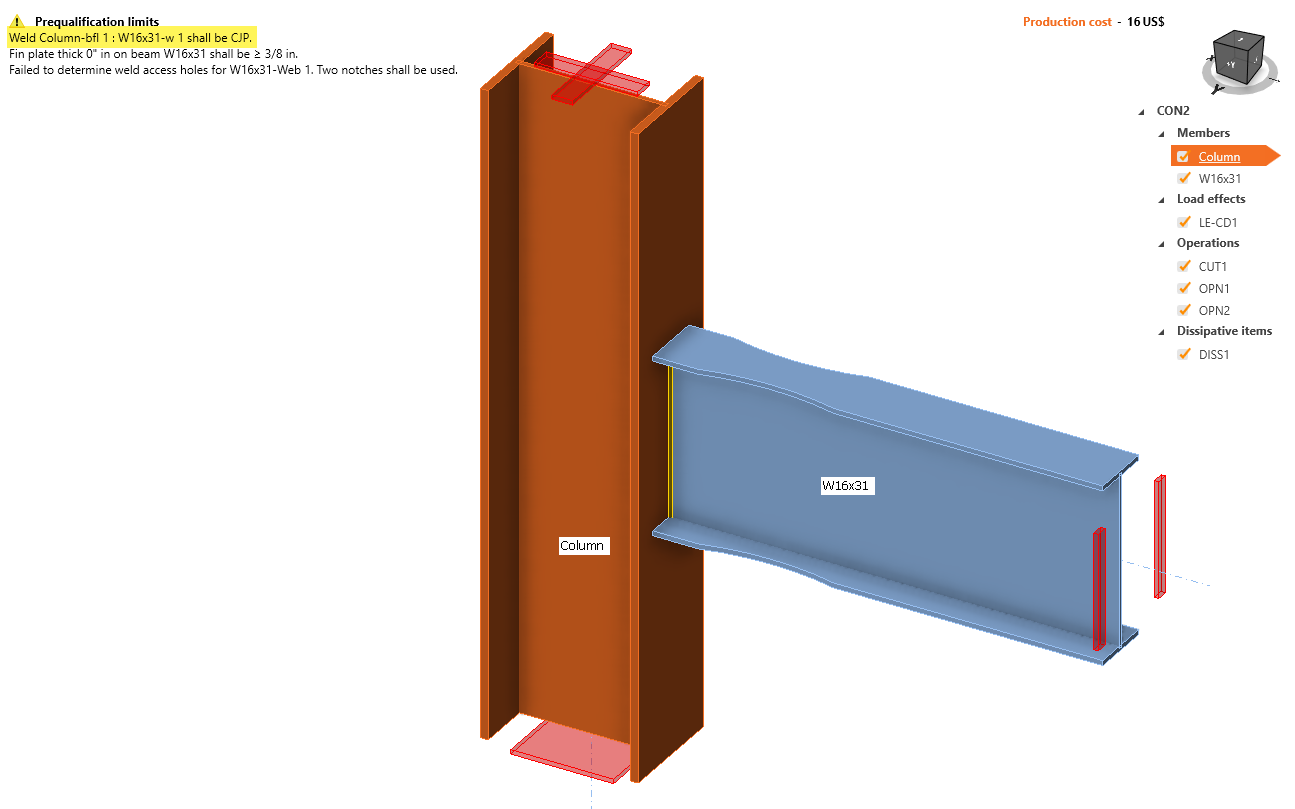
Now that the dissipative item is selected, the Prequalification limits are shown in the top left side of the screen in the model area:
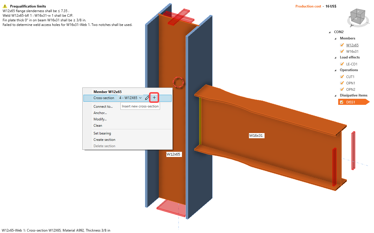
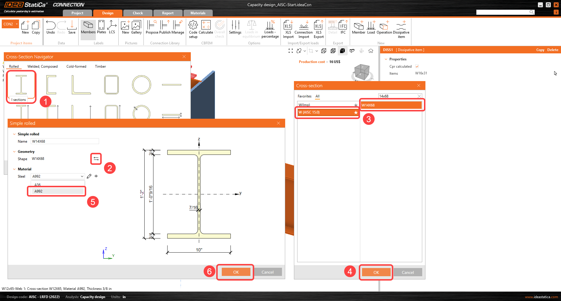
The first warning is related to the AISC 341-16: Chapter D.1.1b and Table D1.1. Limiting Width-to-Thickness Ratios. To fix the first warning, change the Column profile section to W14X68 by right-clicking on the column and then clicking on the plus icon:
Select Wide flange section, scroll down until you find W (AISC 15.0), use the search box, click on W14X68 and click OK.
Change the member's name to Column by clicking on the name W12X65 and pressing F2 keyboard or right-click and select Rename:
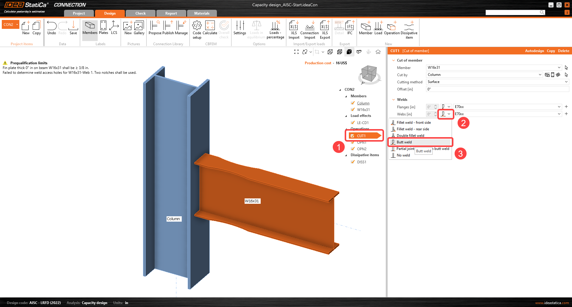
The following warning to fix is related to the weld of the web of the beam to the column flange:
The weld can be changed in the CUT1 operation, change the weld from double fillet weld to Butt weld option:
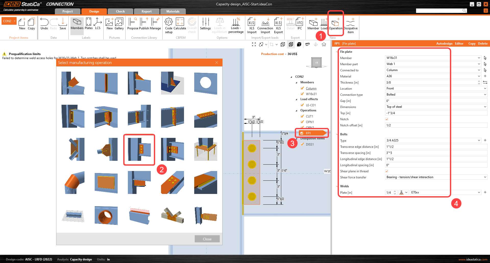
The next warning concerns a shear plate requirement stated in AISC 358 Chapter 5.6 (2) for Special moment frames.
Click on New operation and select Fin plate operation and input the details as shown:
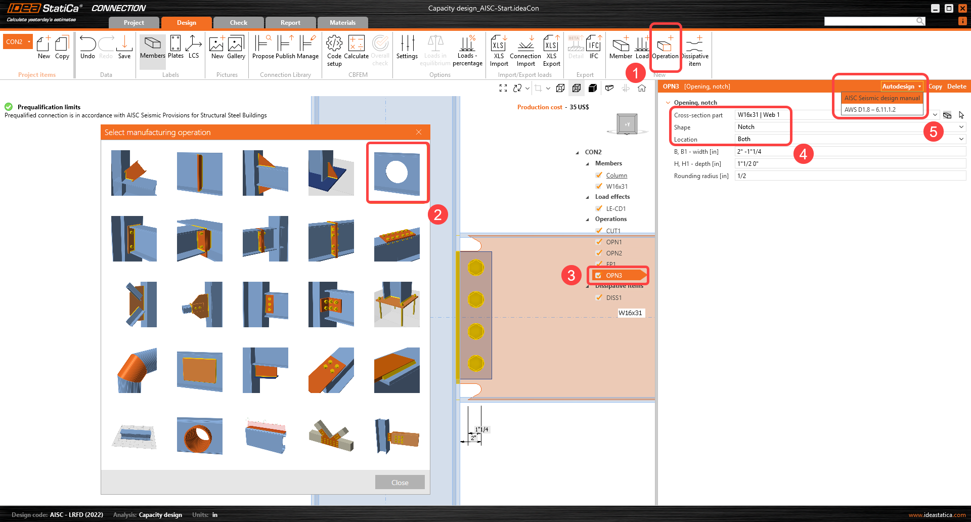
The last warning is about the weld access holes requirement in AISC 358 5.5 (2). To comply with that detailing check, add an Opening operation, select the next input, and use the Pre-design option for notches:
After that operation, the connection meets the prequalification limits from AISC 358 and 341 Standards.
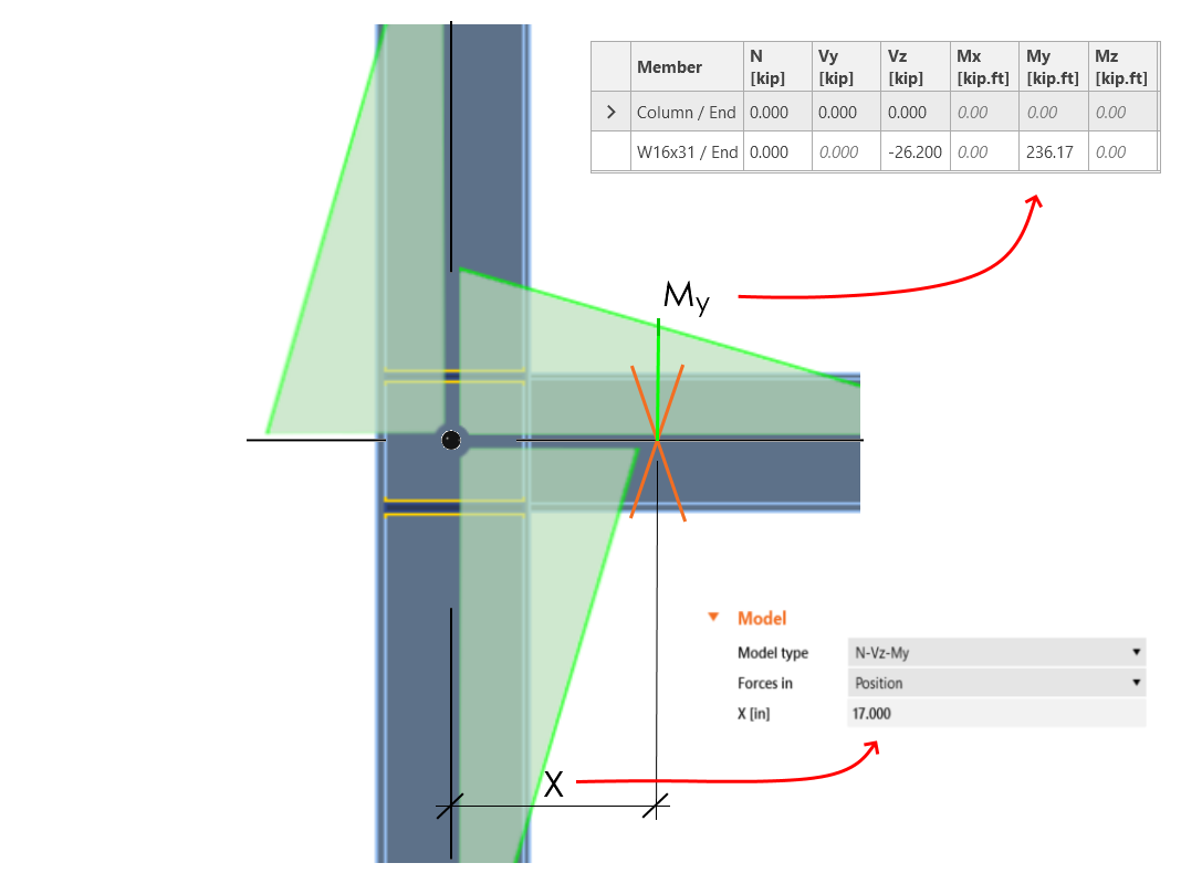
Switch the Forces in parameter to Position, because then the exact acting force position can be defined. The position of the plastic hinge is similar to the position of the acting force: X = 17 inch.
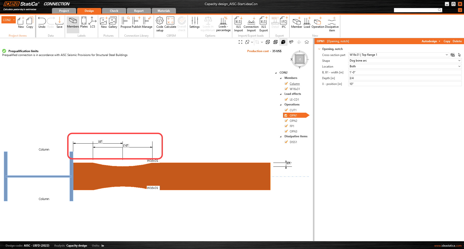
How to know the right position of the plastic hinge? The engineer needs to decide where it will occur. Usually, the plastic hinge is determined in the beam. In this example, it will occur in the middle of the dog bone operation. It’s handy to read the position from the application (wireframe view).
In the next step, the load effects have to be defined. Loads for seismic analysis are code-dependent (the material overstrength factor, strain-hardening factor) and influenced also by yield strength, geometrical characteristics of the cross-section, etc.
Loads for this example were calculated by this procedure:
My = Cpr .Ry .Fy .Zpl,y(RBS) and corresponding shear force Vz = –2 My / Lh, where:
- Ry – ratio of probable to minimal yield strength – AISC 341-16 – Table A3.1; for A992 – Ry = 1.1
- – strain-hardening factor; for A992 – Cpr = 1.15
- Fy – characteristic yield strength; for A992 – Fy = 50.0 ksi
- Fu – characteristic ultimate strength; for A992 – Fu = 65.0 ksi
- Zpl,y(RBS) – plastic section modulus; value for reduced beam section – Zpl,y,(RBS) = 44.80 in3
- Lh – distance between plastic hinges on the beam; Lh = 250 - (2 . 17) = 216 in
My = 1.15 x 1.1 x 50 x 44.80 = 2834 kip.in = 236.17 kip-ft
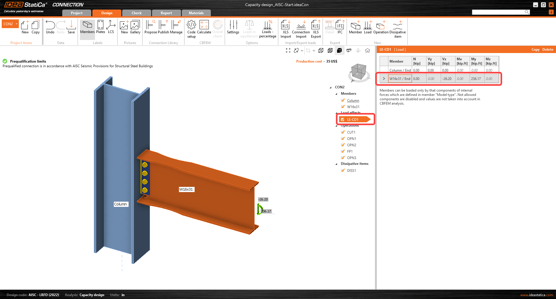
Add the calculated shear force and bending moment as a new Load effect (LE).
The shear force and bending moment must be input with appropriate signs so that the bending moment decreases on the beam in the direction away from the node.
Now the capacity analysis can be started by the Calculate command.
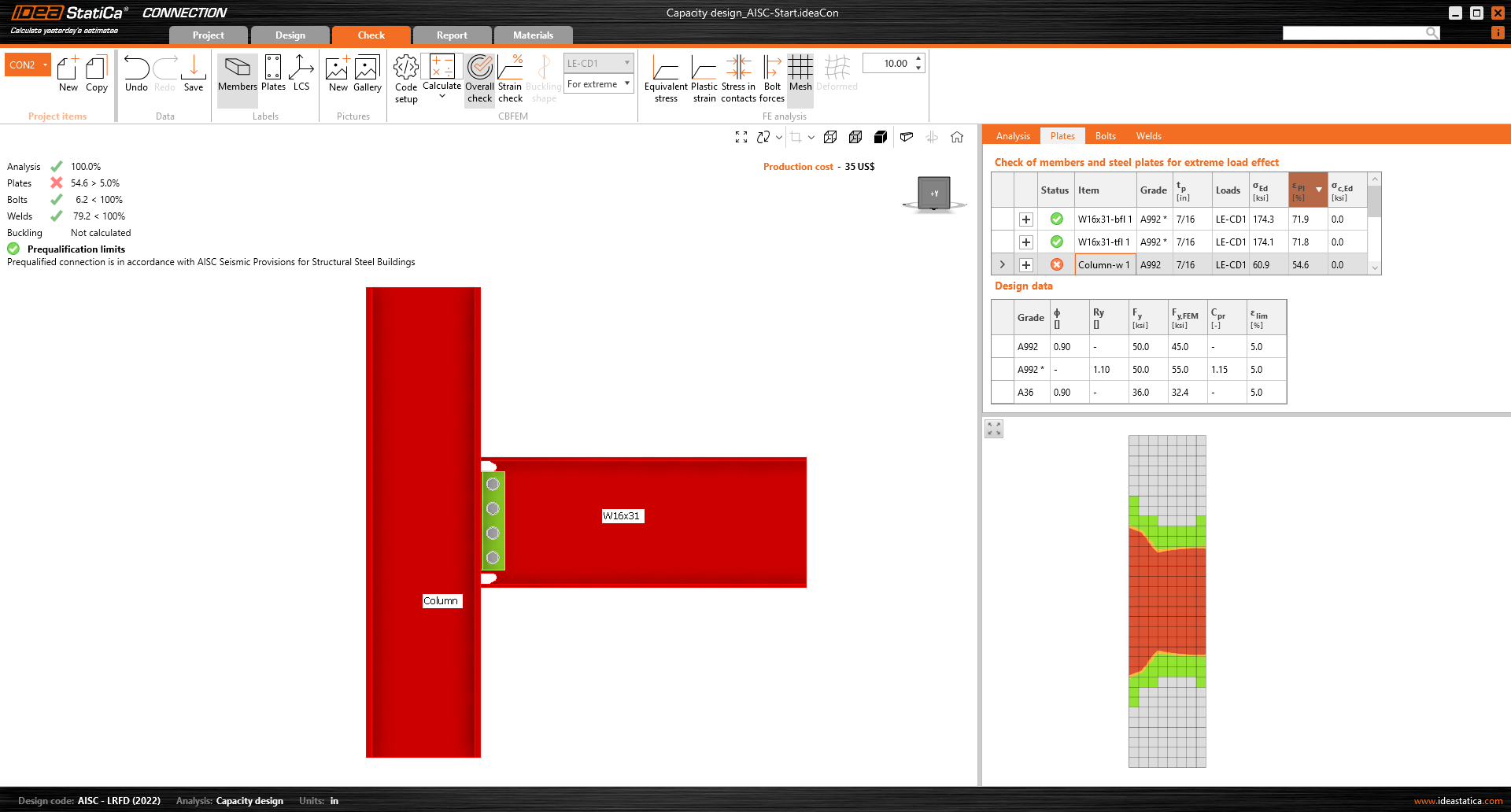
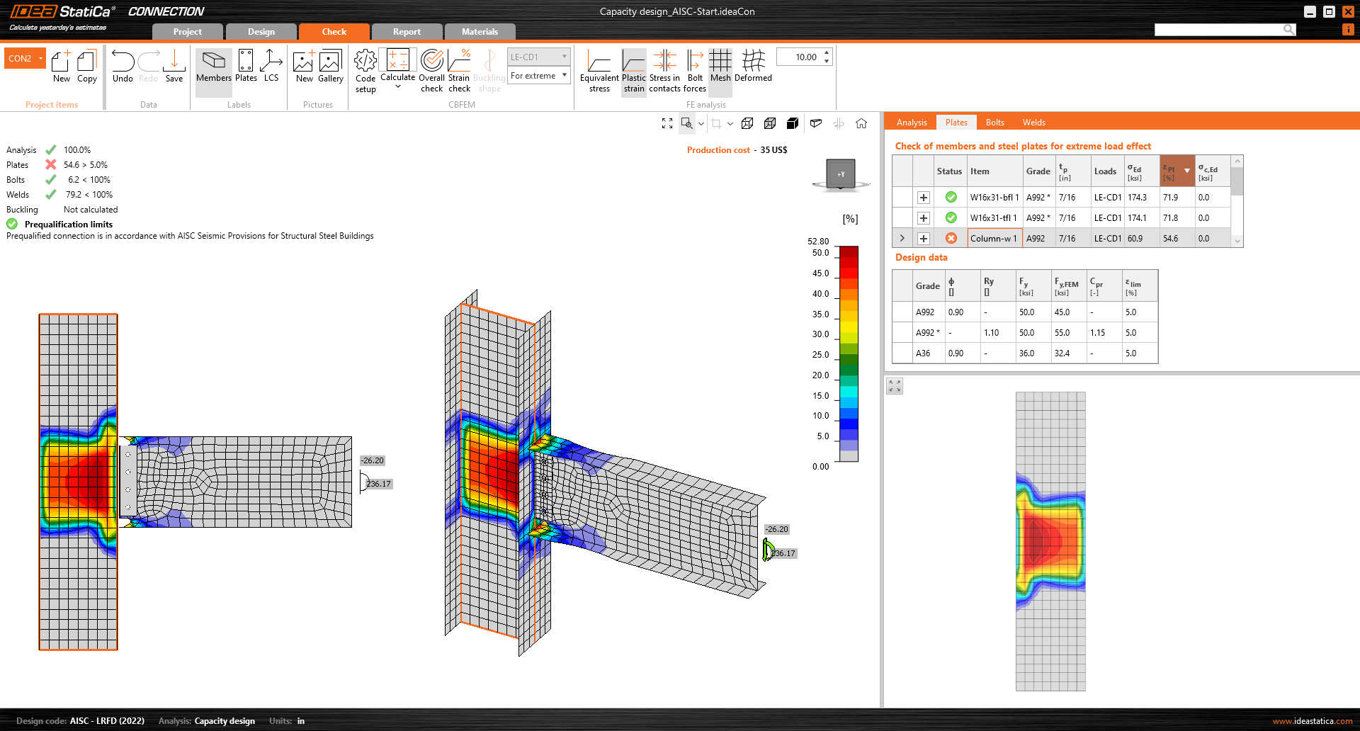
As seen in the results and plastic strain view, the column has an extreme plastic strain, and the main objective of the Capacity design together with prequalified connections from AISC 358 design process, is to design a strong column-weak beam system. Therefore, the yielding and plastic hinge formation is intended to occur in the dissipative item (selected beam), and in the Reduced beam section type of connection, the intention is to have the maximum plastic strain at the central part of the reduced section of the beam.
The design approach is to push the failure into the beam. The following steps are meant to increase the strength of the panel zone of the column.
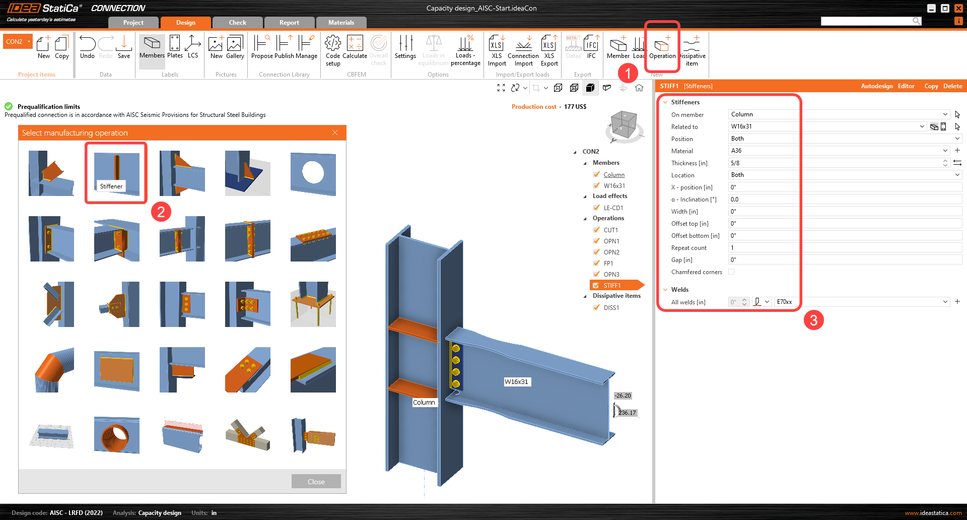
We can start by adding four stiffeners into the column aligned to the beam flanges. Set the thickness of the stiffeners to 5/8".
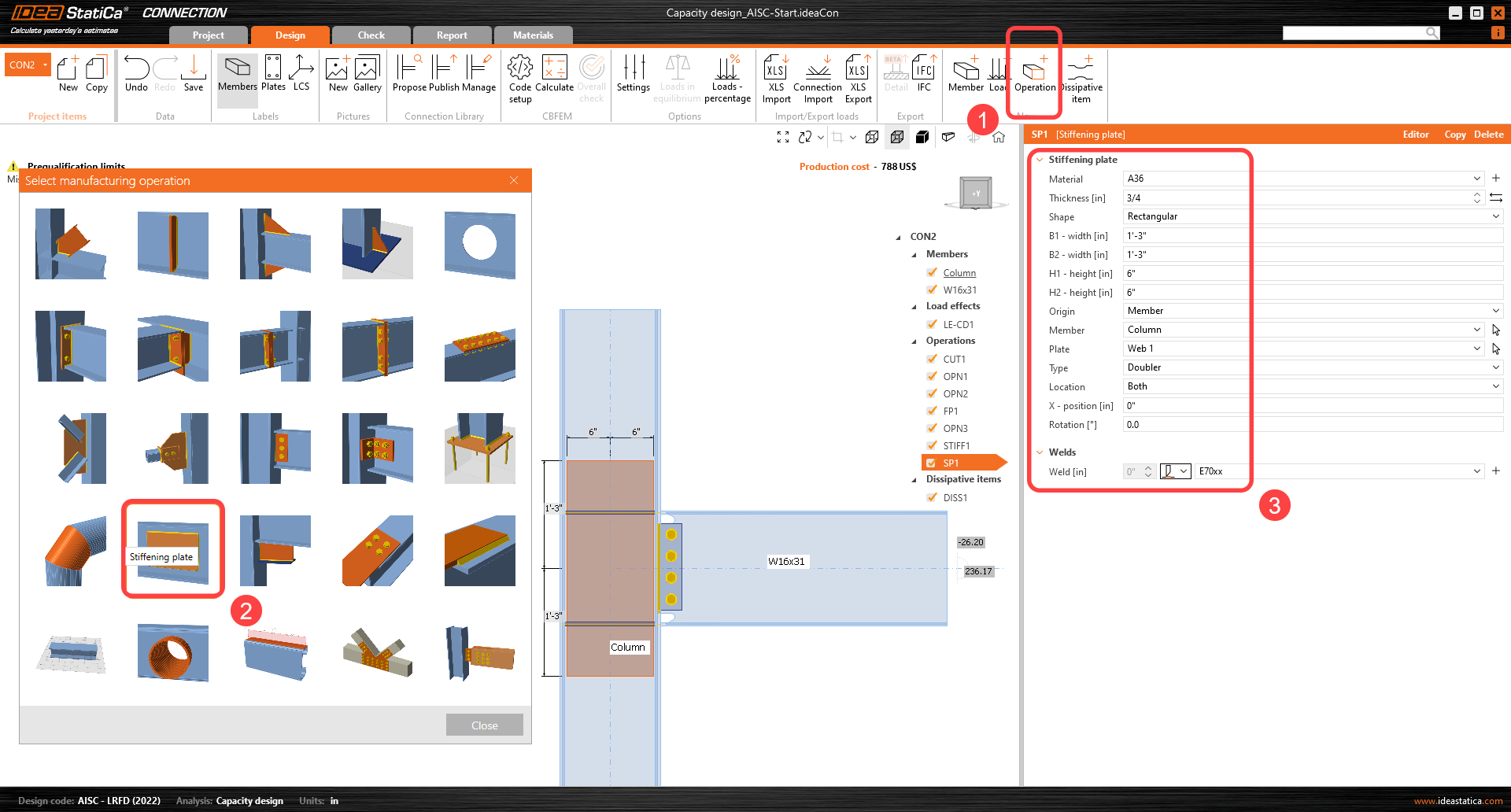
To increase column load capacity, add a doubler to both sides of the web (add Stiffening plate manufacturing operation).
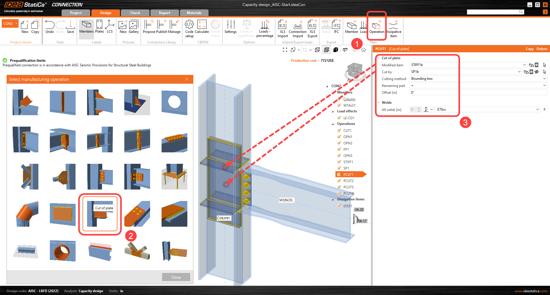
The stiffeners at the column web need to be cut and welded to the doublers by the Cut of the plate manufacturing operation.
Repeat the cut of the plate operation four times to connect the other front/back stiffeners to the doublers.
*Tip: Right-click on the first cut operation, copy it as necessary, and hover the mouse over the plates to see the names of the plates to cut.
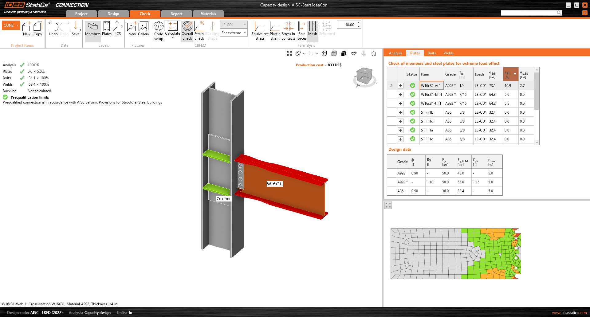
All design modifications are now complete, run Calculate in the Check tab. You can see that all components (like welds and bolts) passed the code check. The plastic strain of the dissipative item plates does not influence overall results.
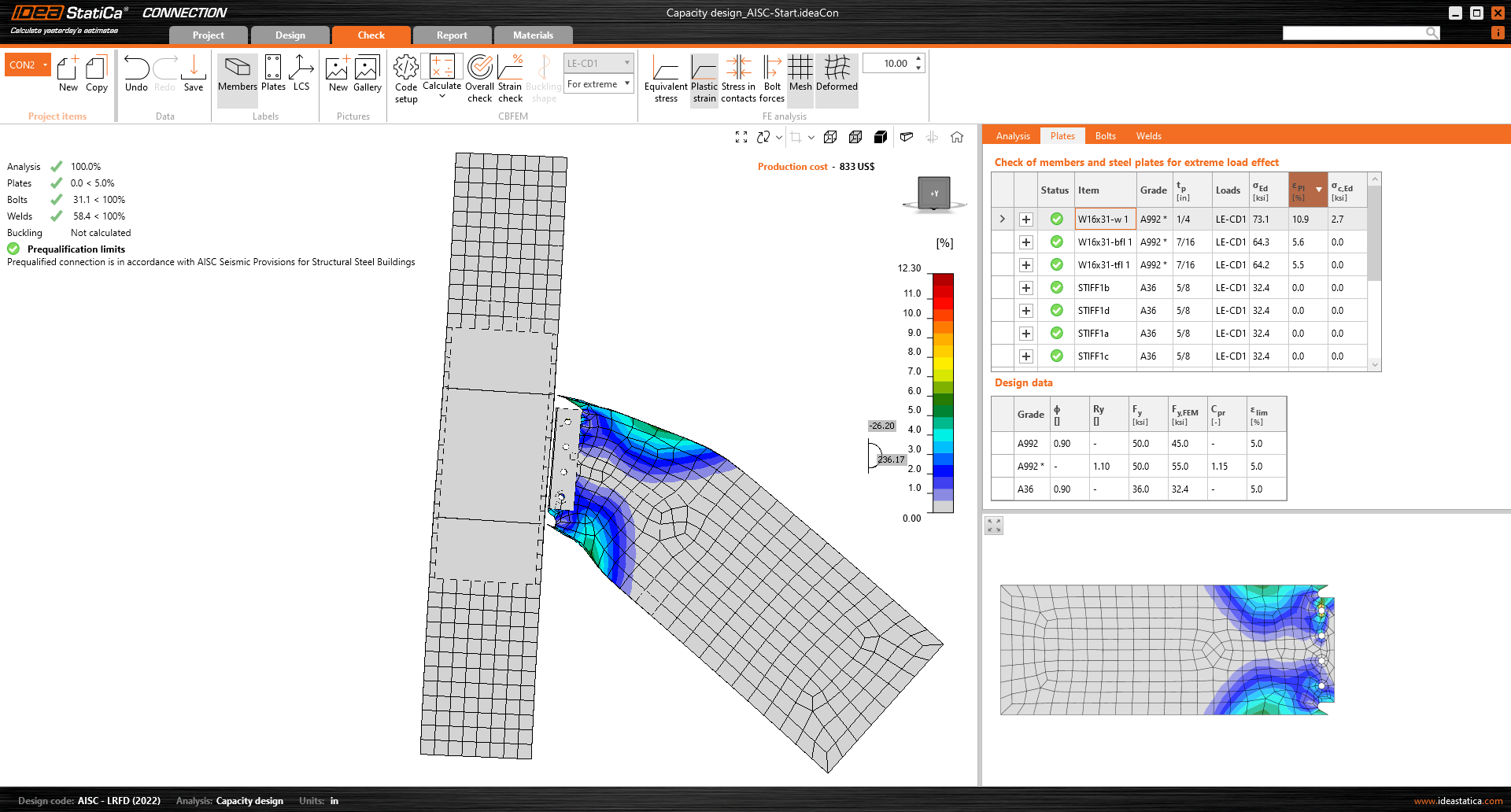
The occurrence of the plastic hinge can be explored in the Plastic strain analysis window.
The plastic hinge appeared at the expected location, and this joint passed the checks required by the capacity design.
For a better understanding of the results, see the Theoretical Background.
4 Report
Finally, you can review the Report. IDEA StatiCa offers a fully customizable report to print out or save in an editable format.
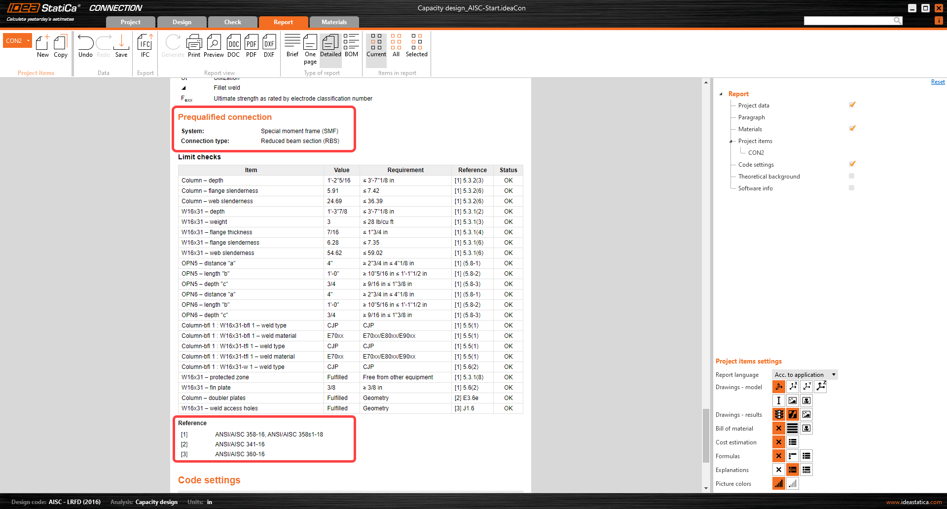
At the end of the detailed report, there is a list of the prequalified connection detailing checks with its reference and status:
You have performed a capacity design check of a prequalified structural connection according to the AISC 358 and AISC 341.
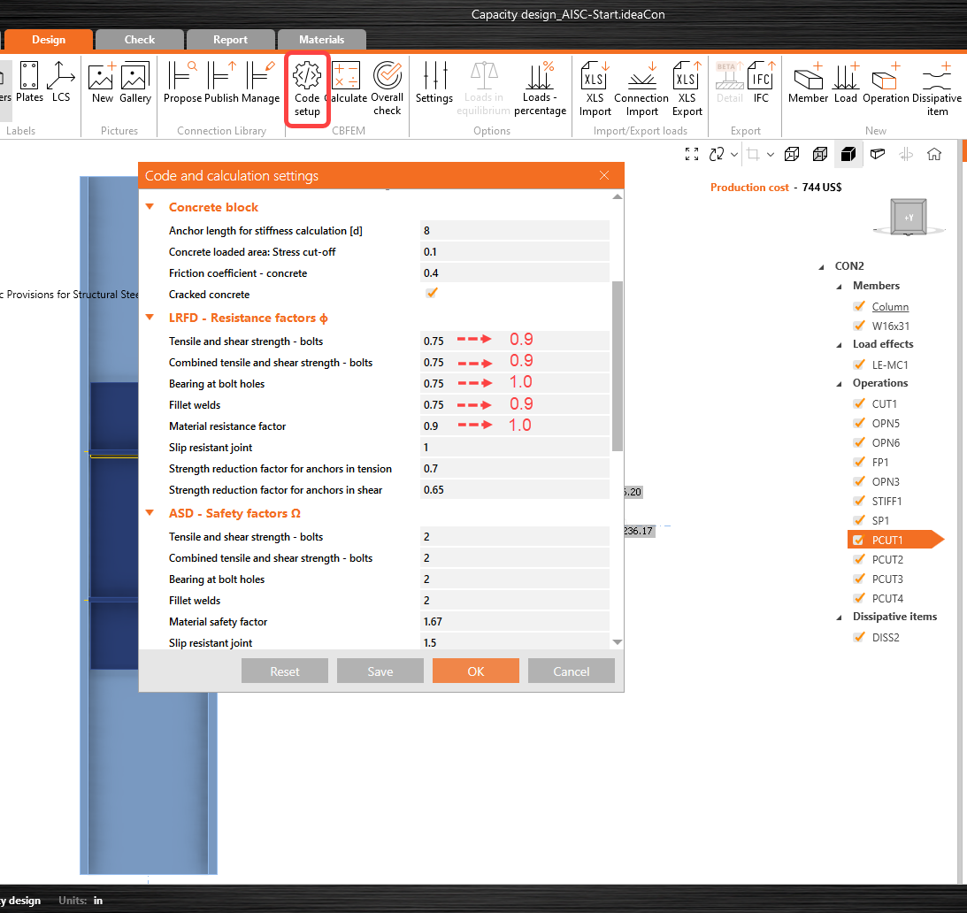
Resistance factors
Since the design requirements for 'prequalified' connection are met, and the available strengths are calculated in accordance with AISC 358-16, resistance factors ϕ shall be taken as follows:
For ductile limit states ϕd = 1.00
For nonductile limit states ϕn = 0.90
These factors can be edited in IDEA StatiCa Connection 'Code setup':


