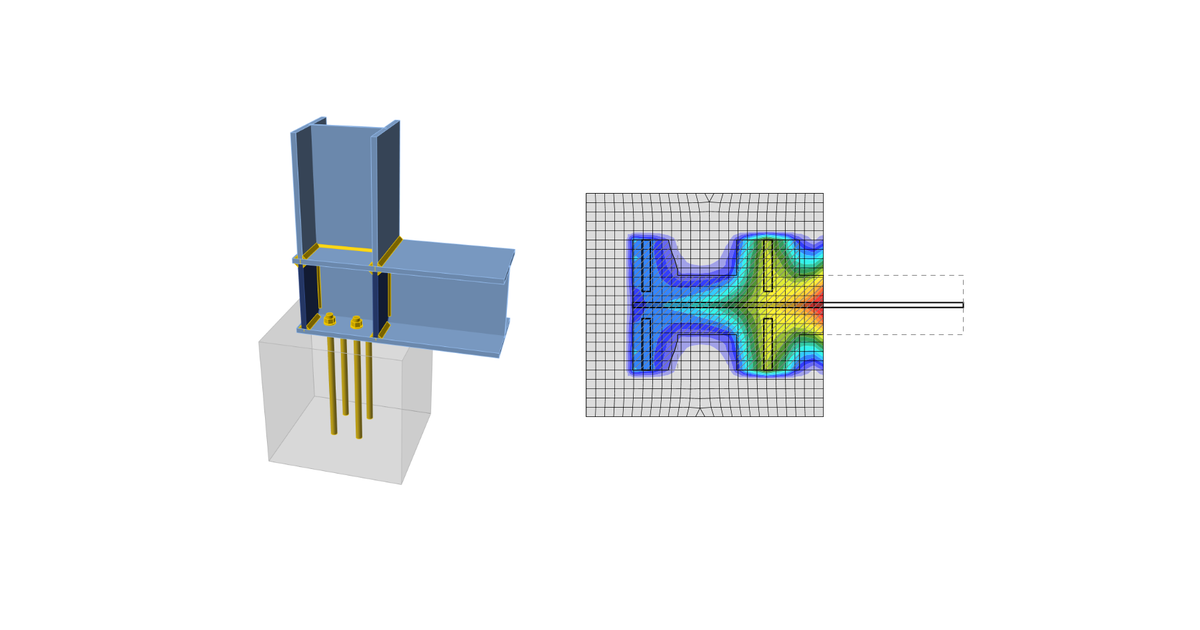
Code-check of concrete blocks (AISC)
Concrete below base plate is simulated by the Winkler subsoil with uniform stiffness, which provides the contact stresses. The average stress at the loaded area in contact with the base plate is used for compressive check.
Concrete in compression
Concrete design bearing strength in compression is designed according to AISC 360-16, Section J8. When the supporting surface of the concrete is larger than the base plate, the design bearing strength is defined as
where:
- f'c – concrete compressive strength
- A1 – base plate area in contact with a concrete surface (upper surface area of the frustum)
- A2 – concrete supporting surface (geometrically similar lower area of the frustum having its slopes of 1 vertical to 2 horizontal)
The assessment of concrete in the bearing is as follows
σ ≤ ϕc fp(max) for LRFD
σ ≤ fp(max) / Ωc for ASD
where:
- σ – average compressive stress under the base plate
- ϕc = 0.65 – resistance factor for concrete
- Ωc = 2.31 – safety factor for concrete
Transfer of shear forces
Shear loads can be transferred via one of these options:
- Shear lug,
- Friction,
- Anchor bolts.
Shear lug
Only LFRD is available. The shear load is transferred via the shear lug. The concrete in bearing and, unless reinforcement is provided to develop the required strength, concrete breakout checks are necessary.
The bearing capacity of shear lug against concrete is determined according to ACI 349-01 – B.4.5 and ACI 349-01 RB11 as:
ϕPbr = ϕ 1.3 f'c A1 + ϕ Kc (Ny – Pa)
where:
- ϕ = 0.7 – strength reduction factor for bearing on concrete according to ACI 349
- f'c – concrete compressive strength
- A1 – projected area of the embedded shear lug in the direction of the force, excluding the portion of the lug in contact with the grout above concrete member
- Kc = 1.6 – confinement coefficient
- Ny = n Ase Fy – yield strength of tensioned anchors
- Pa – external axial load
The concrete breakout strength of the shear lug according to ACI 349 – B11 is:
where:
- ϕ = 0.85 – strength reduction factor for shear according to ACI 349
- AVc – effective stress area defined by projecting a 45° plane from the bearing edges of the shear lug to the free surface in the direction of the shear load. The bearing area of the shear lug is excluded from the projected area
If the concrete breakout resistance in Code setup is disabled, user is provided with the force that needs to be transferred via reinforced concrete.
Friction
The shear load is transferred via friction. The shear resistance is determined as:
ϕc Vr = ϕc μ C (LRFD)
Vr / Ωc =μ C / Ωc (ASD)
where:
- ϕc = 0.65 – resistance factor (LRFD)
- Ωc = 2.31 – safety factor (ASD)
- μ = 0.4 – coefficient of friction between base plate and concrete (recommended value 0.4 in AISC Design guide 7 – 9.2 and ACI 349 – B.6.1.4, editable in Code setup)
- C – compressive force
Anchor bolts
If the shear load is transferred via anchor bolts only, the shear force acting on each anchor is determined by FEA and anchor bolts are assessed according to ACI 318-14 as described in the following chapters.


