Concrete in compression
Type of connection: Column base
Unit system: Metric
Designed acc. to: EN 1993-1-8 and EN 1992-1-1
Investigated: Concrete in compression
Steel: Grade S235
Bolts: M20 Grade 4.6
Concrete: C20/25
Geometry
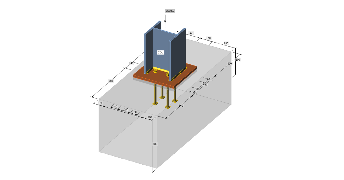
Pinned column base is designed for the column HEB 300. The base plate has dimensions 460×460 mm. Anchor bolts are M20 4.6 placed inside the column boundary to reduce the stiffness of the joint. The base plate is grouted with the expected thickness of 30 mm.
Applied load
The column is loaded by compressive force 2 000 kN.
Manual calculation
General
Three components are examined: column flange and web in compression, concrete in compression including grout, welds. All components are designed according to EN 1993-1-8 and EN 1992-1-1. In this example, only equivalent T-stub in compression according to EN 1993-1-8 – Cl. 6.2.5 is investigated.
Elastoplastic behavior of the base plate is expected in the code. The uniform compressive stress under the effective area of the base plate equal to design bearing strength of the concrete increased by triaxial stress state, fjd, is estimated at the design compressive resistance of the joint. The effective area Aeff is constructed using additional bearing width, c. This value is calculated using following formula:
\[ c=t\sqrt{\frac{f_y}{3f_{jd} \gamma_{M0}}} \]
where:
- t – base plate thickness
- fy – base plate yield strength
- fjd – design bearing strength of the concrete
- γM0 = 1.0 – partial safety factor for steel
The cross-section of the column is increased by this additional bearing width unless it exceeds the base plate area. The membrane forces are neglected for simplicity, although they may be quite significant, e.g. in case of closed section columns.
The design bearing strength of the concrete fjd is determined according to the following equation:
\[ f_{jd} = \beta_j \frac{F_{Rdu}}{A_{eff}} \]
where:
- βj – the foundation joint material coefficient, which may be taken as 2/3 provided that the characteristic strength of the grout is not less than 0.2 times the characteristic strength of the concrete foundation and the thickness of the grout is not greater than 0.2 times the smallest width of the steel base plate. In cases where the thickness of the grout is more than 50 mm, the characteristic strength of the grout should be at least the same as that of the concrete foundation.
- FRdu – the concentrated design resistance force given in EN 1992-1-1 – Cl. 6.7; the bearing area Ac0 is the effective area Aeff and the design distribution area Ac1 must be geometrically similar and concentric to the bearing area. The slope of spreading is quite steep, height to width 2:1.
The increase in concrete strength thanks to the triaxial stress in concrete may be expressed by a concentration factor,
\[ k_j = \sqrt{\frac{A_{c1}}{A_{eff}}} \le 3.0 \]
The design bearing strength of the concrete is then
\[ f_{jd} = \beta_j k_j f_{cd} \]
The design compressive resistance of the joint is Nc,Rd = fjd Aeff.
This algorithm is in fact an iterative process because the effective area depends on the design bearing strength of the concrete and vice versa. Usually, the 1st iteration step is chosen to take the area of the base plate as the effective area. With decreasing effective area the concentration factor is increasing and with further iterations, the design compressive resistance of the joint is increasing as well. Especially for unnecessarily large base plates, the increase may be significant but usually, only the first iteration is enough for the design compressive resistance to exceed the design compressive load.
Example
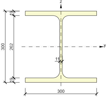
The cross-section of the column is shown in the following figure:
The first step is to calculated the design bearing strength of the concrete with the assumption that the whole base plate is the effective bearing area, Ac0 = 4602 = 211 600 mm2. The design distribution area must be geometrically similar and concentric to the base plate. The concrete offset is 500 mm in one direction but only 100 mm in the other. The design distribution area can be therefore increased by 100 mm in all directions. The height of the concrete block is sufficient, h = 600 mm ≥ (660 – 460) = 200 mm. The design distribution area is Ac1 = 6602 = 435 600 mm2. The concentration factor is
\[ k_j = \sqrt{\frac{A_{c1}}{A_{c0}}} = \sqrt{\frac{435600}{211600}} = 1.435 \]
Finally, the design bearing strength of concrete is
\[ f_{jd} = \beta_j k_j f_{cd} = 0.67 \cdot 1.435 \cdot 13.333 = 12.756 \, \texttt{MPa} \]
Next, the additional bearing width is calculated:
\[ c=t\sqrt{\frac{f_y}{3f_{jd} \gamma_{M0}}} = 25 \sqrt{\frac{235}{3 \cdot 12.756 \cdot 1}} = 62 \, \texttt{mm} \]
And the effective area may be constructed:
Aeff = 2 · (2 · 62 + 19) · (300 + 2 · 62) + (262 – 2 · 62) · (2 · 62 + 11) = 139 894 mm2.
The design compressive resistance of the joint is Nc,Rd = fjd Aeff = 12.756 · 139 894 = 1 784 kN. The second iteration is necessary.
The effective area is taken as the bearing area and it spreads into a square with side size of 660 mm. The concentration factor for the second iteration is:
\[ k_j = \sqrt{\frac{A_{c1}}{A_{c0}}} = \sqrt{\frac{435600}{139894}} = 1.765 \]
The design bearing strength of concrete is:
\[ f_{jd} = \beta_j k_j f_{cd} = 0.67 \cdot 1.765 \cdot 13.333 = 15.685 \, \texttt{MPa} \]
The additional bearing width is:
\[ =t\sqrt{\frac{f_y}{3f_{jd} \gamma_{M0}}} = 25 \sqrt{\frac{235}{3 \cdot 15.685 \cdot 1}} = 56 \, \texttt{mm} \]
The effective area is:
Aeff = 2 · (2 · 56 + 19) · (300 + 2 · 56) + (262 – 2 · 56) · (2 · 56 + 11) = 126 394 mm2.
The design compressive resistance of the joint is:
Nc,Rd = fjd Aeff = 15.685 · 126 394 = 1 982 kN.
The following iterations are shown in the form of a graph. It can be seen that the three iterations are usually enough and the design compressive resistance does not rise significantly afterward.
Results of IDEA Connection
The effective area in bearing is in IDEA Connection determined using intersection of two areas to allow check for any loading and any column shape including ribs or wideners. One area is determined by finite element analysis and shows the area of base plate in contact with concrete. The second area is the area calculated by the algorithm in component method using additional bearing width c. The software uses iterations until the difference between iterations of additional bearing width is less than 1 mm.
The compressive resistance of this base plate according to IDEA Connection is 1 992 kN.
Comparison
The resistance of concrete in bearing in IDEA Connection (1 992 kN) is in this case slightly lower than using hand calculation with several iterations (2 055 kN) because the effective area is slightly smaller. The difference is only 3 %.


