
Eccentrically loaded anchoring in 3D Detail
The following tutorial explains how to model a footing completely in IDEA StatiCa 3D Detail. The topic of import from the Connection application to 3D Detail is covered in the tutorial BIM link Connection to 3D Detail.
1 New project
Start by launching the IDEA StatiCa application. In the main window of IDEA StatiCa, open the Detail application to define a new project.

Select 3D Model type and the empty template. Adjust the parameters according to the picture below (Concrete C25/30, Concrete cover 45 mm). Finally, click Create.

2 Geometry
A completely blank project has been created, and you now have to set up everything from scratch. Next you must define a new solid block.

Next step is to support the block by adding a new Surface Support. The user can set different stiffnesses in each direction. By default, the support in the vertical direction is set to "compression only" reflecting the fact that soil can transfer no load in tension. The value of the soil spring stiffness is usually determined in collaboration with a geotechnical engineer. Generally, it depends on the subsoil, foundation depth, the shape of the foundation, and the applied loads. Input value kz = 25 MN/m3 corresponding to good foundation conditions (dry sand). The surface support can be set to a whole surface or only to a part defined by a polyline. In this case, use the default setting Whole surface.

Please note that the application does not replace the geotechnical verification of the foundation. It doesn't check the value of soil pressure and it doesn't code-check the stability of the footing. If the bending load is set too high, the footing will overturn (as indicated by a divergent analysis or large deformations/motions).
The next step is to define the transfer devices. The base plate will be the first item to be created. You will define a square steel base plate located near the edge of the concrete block. The shear force is transferred via friction between the steel plate and the concrete surface. Alternatively, the shear transfer can be assigned to a shear lug or to anchors.

With the base plate successfully defined, it is now time to move to the anchors. The anchors shall be made of steel grade 10.9. That means you have to define a new material as only reinforcement steel is available by default at the present moment. Switch to the Materials tab and copy the existing reinforcement B500B.

Now, edit the new material and save it under a new name Steel 10.9.

Back in the Design tab, add a new Single Anchor.
Two types of anchors can be selected:
Cast-in-place anchors: Pre-installed anchors with the same properties in bond as the reinforcement bars
Adhesive anchors: Post-installed (chemical anchors) with the option to customize your bond strength based on the actual bond strength.
Cast-in-place is established as the default. Use the adhesive anchors instead and set the bond strength to 8.0 MPa. The bond strength value has to be set based on the technical documentation provided by the adhesive anchor's manufacturer.

It is important to interconnect the anchor with the base plate because the loads will be applied to it. Copy the anchor three times and adjust the positions.

3 Reinforcement
Select the Rebar-Assembly(1)-->Group of the bars 3D(2) and filling out the Diameter, Properties and Geometry(3).

Copy the operation and change the Surface. All the other options are retained.

Copy the operation again and modify the parameters to define the horizontal reinforcement.

The last step will be to define the shear reinforcement. You can model it as vertical bars with a perfect bond on both ends. Copy the operation and modify the parameters for the last time.

4 Loads and combinations
There will be three load cases: LC1: Self-weight, LC2: permanent load, LC3: Variable.
Start with the Self-weight.

In the next step the permanent load acting on the base plate will be defined. You can define six components of the point load and its position on the base plate.

Copy the load case LC3 and modify the parameters. This is the variable load.

Now, create a design load combination.

5 Calculation and Check
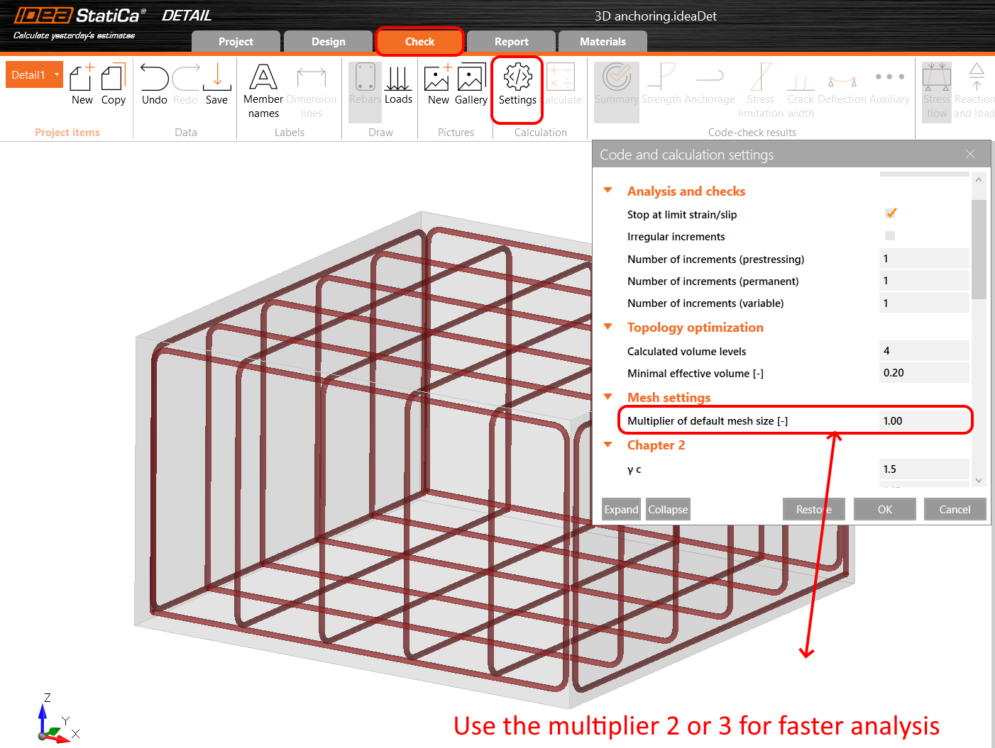
Before running the analysis, we highly recommend changing the mesh multiplier to two in order to speed up the simulation process. This step is not mandatory but can reduce computational time and help detect any divergence issues. If everything works smoothly and no problems arise, you can switch back to a multiplier of one.
When the analysis is complete, a brief overview of the results is displayed in the top left corner of the screen. You can switch to the Check tab. Summary results will be displayed, showing the stress flow in both the concrete and the reinforcement.

Effective Principal Stress
The effective principal stress(EPS) in concrete is determined based on the volume behaviour of the concrete block. The areas that experience the highest load are identified and highlighted. In order to gain insight into the confinement in contrast with uniaxial compression, the effective stress is calculated using the kappa factor. More information about effective principal stress is enclosed in this article: 3D Detail – reinforced concrete footings (BETA).

Sections
You want to check what is happening inside the concrete block, too. For this purpose, you can define a section. You can define any plane you like and set its position.

You can define any number of sections in any direction. To switch back to the default view, click the sections icon.

Stress in rebars
In the Reinforcement Check, you can display stress and strain of all rebars and anchors. You can note that the anchor close to the corner has the maximum utilization.

Anchorage
The Anchorage tab lets the user display the bond stress and the total force in each bar and anchor.

The anchors should be always checked according to the code. You can read more about how the checks work in Connection application and Detail application in this article: Complete code-check of anchors and concrete block with IDEA StatiCa
There are some checks, which the Connection application cannot perform. Those missing checks in IDEA StatiCa Connection are bypassed using the 3D Detail:
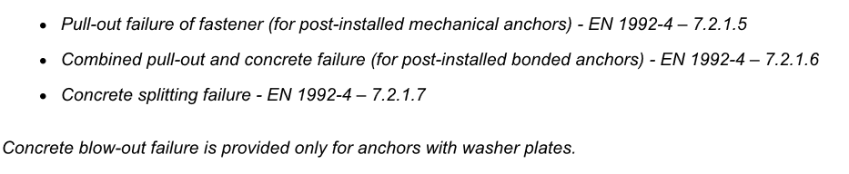
Moreover, the Detail application automatically takes into account the reinforcement near the anchor, which can significantly increase the loading capacity of the anchors where the concrete cone failure is governing.
Deformations
It is highly recommended to check the deformation after analysis to ensure that the model is not experiencing large deformation, large rotation or any finite element is distorted. This will provide an overview of the analysis results and help identify any issues that may have arisen during the analysis.
Move to Auxiliary and turn on the Deformation.

6 Report
At last, go to the Report Preview/Print. IDEA StatiCa 3D Detail offers a fully customizable report to print or save in an editable format.

You have learned how to input a concrete block with reinforcement in IDEA StatiCa 3D Detail, set supports, and use load-transferring devices. You know how to input loads and define load combinations, and lastly, you learned how to perform analysis and code checks.