Joint design resistance
The designer usually solves the task of designing the connection/joint to transfer the known design load. But it is also useful to know how far the design from the limit state is, i.e., how big the reserve in the design is and how safe it is. This can be done simply by the type of analysis – Joint design resistance.
The user inputs design load like in a standard design. The software automatically proportionally increases all load components until one of the included checks does not satisfy.
DR analyses conduct checks for the following components:
- Plastic strain in plates
- Bolts – shear, tension, and a combination of tension and shear
- Anchors – tension and shear steel resistance
- Welds
Please note that other components not included in the above list will not be checked due to unknown directions of forces in components. For this reason, an EPS analysis should always be conducted to ensure that all checks are correctly performed.
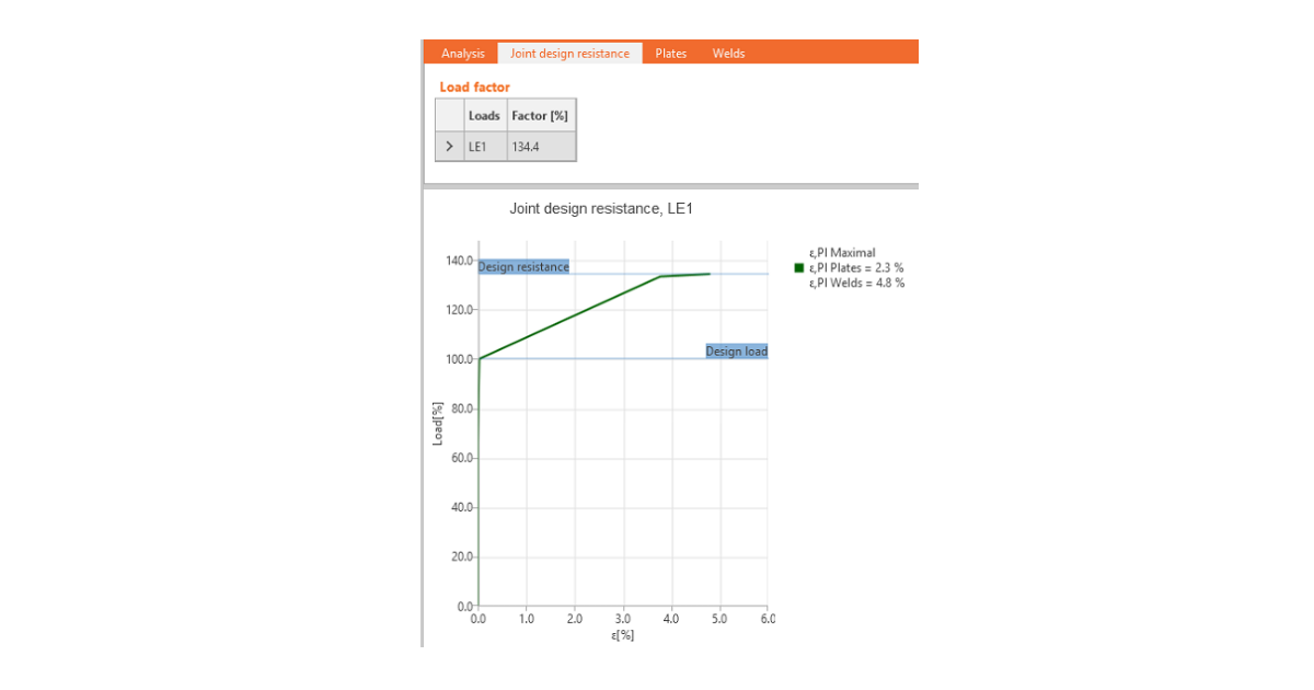
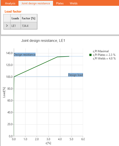
The user gets the ratio of maximal load to the design load. Also, a simple diagram is provided.
The results of user-defined load cases are shown unless the Joint design resistance Factor is smaller than 100 % which means that the calculation did not converge, and the last converged step of the load case is shown.


