1. The objective
The objective of this article is the verification of the LBA (linear bifurcation analysis) module of the IDEA Member application. Beams in bending are analyzed and the influence of different boundary conditions and load positions is investigated. The resulting elastic critical moments from IDEA Member are compared to the elastic critical moments based on Annex I of EN 1999-1-1 [1]. Numerical solution from LTBeam software [2] is also presented.
2. Model description
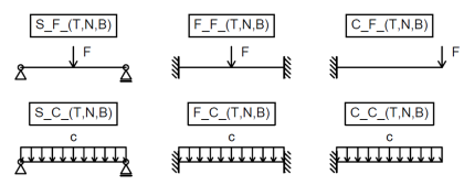
A total of 18 individual cases was analyzed to verify the LBA module. All of them share the same cross-section IPE 300 and the same steel grade S 355. Three different boundary conditions were investigated (S – simple, F – fixed, C – cantilever), each with two load cases (F – force; C – continuous). Three load positions in relation to the shear center are verified (T – top, N – neutral, B – bottom).
Fig. 1: Various boundary conditions and load cases used for verification
All cases are designated in the following manner: “C_F_T”, where “C” indicates boundary conditions, “F” the load case and “T” the load position relative to the shear center.
3. Analytical solution
The three-factor formula found in Annex I of EN 1999-1-1 [1] is used to calculate the elastic critical moment for lateral-torsional buckling of the beams:
\[ M_{cr} = \mu_{cr} \frac{\pi \sqrt{E I_z G I_t}}{L} \]
\[ \mu_{cr} = \frac{c_1}{k_z} \left [ \sqrt{1+\kappa_{wt}^2 + (C_2 \zeta_g - C_3 \zeta_j)^2} - (C_2 \zeta_g - C_3 \zeta_j) \right ] \]
The Annex B of ECCS - N° 119 [3] is used to calculate the coefficients C1 and C2 for the cantilever.
Fig. 2: Buckling modes for the three different boundary conditions
4. Results
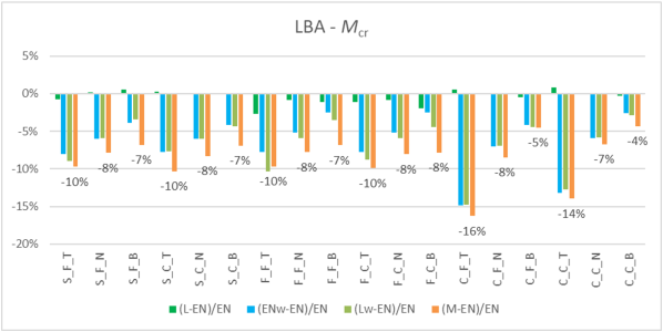
The elastic critical moment from IDEA Member (M) is compared to an analytical value for a rolled cross-section (EN) and for its representation without the web-flange radii (ENw). Furthermore, the same two sets of values are presented as an output from the LTBeam software (L, Lw).
Tab. 1: Resulting elastic critical moments
The results of LBA are conservative (10–16 %) for the top flange load positions. The other load positions are less conservative (< 10 %).
Chart 1: Elastic critical moment values
Chart 2: Elastic critical moment comparison
The slightly conservative results of IDEA Member are caused by the missing web-flange radii of the shell representation of a cross section in the IDEA Member and resulting lower torsional stiffness. This is confirmed by the LTBeam software (Lw), as well as the analytical solution (ENw).
5. Literature and References
[1] EN 1999-1-1: Eurocode 9: Design of aluminium structures - Part 1-1 : General structural rules, CEN, 2006.
[2] LTBeam software v. 1.0.11, CTICM, available at https://www.cesdb.com/ltbeam.html
[3] Rules for Member Stability in EN 1993-1-1, Background documentation and design guidelines, ECCS - N° 119, 2006.


