
Tri-axial stress – the active confinement effect
Introduction
The confinement effect in concrete structures refers to the phenomenon where the strength and ductility of concrete are significantly improved due to lateral pressure (active) or confinement provided by surrounding materials (passive), such as steel reinforcement or external jackets. This effect is particularly important in enhancing the performance of concrete in compression, especially under high loads.
Here are the key aspects of the confinement effect in concrete structures:
- Increased strength: Confinement increases the compressive strength of concrete. When lateral pressure is applied, it restrains the lateral expansion of the concrete, allowing it to sustain higher axial loads before failing.
- Enhanced ductility: Confined concrete exhibits greater ductility, meaning it can undergo larger deformations before failure.
- Behavior under load: Confinement changes the failure mode of concrete from a brittle, sudden failure to a more ductile, gradual one. This change in failure mode is beneficial for the safety and integrity of structures under extreme loading conditions.
- Design considerations: The design of confined concrete members involves calculating the amount and arrangement of confining reinforcement to achieve the desired strength and ductility. Standards and codes, such as EN (Eurocode) guidelines, provide formulas and guidelines for designing confined concrete elements.
- Applications: Active confinement is considered while designing, for example, partially loaded areas, concrete hinges, etc.
In the following figure, you can notice how the stress-strain diagram and bearing capacity can differ for unconfined and confined concrete.
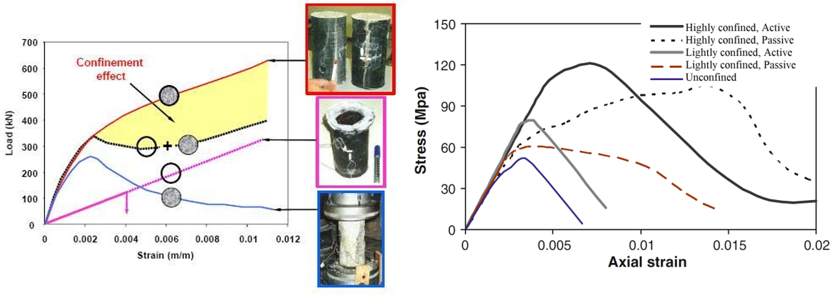
\[ \textsf{\textit{\footnotesize{Fig. 1\qquad Confinement effect and influence on the bearing capacity of structures}}}\]
Before we get into the example itself, let's recall how the concrete material is defined in the application.
Concrete material definition in IDEA StatiCa Detail
3D CSFM defines the concrete behavior based on the Mohr-Coulomb plasticity theory for monotonic loading.
In general, for a given angle of internal friction of the concrete, which is around φ = 30°, the tensile and compressive strengths of the concrete Mohr's circles can be constructed as in Figure 2.
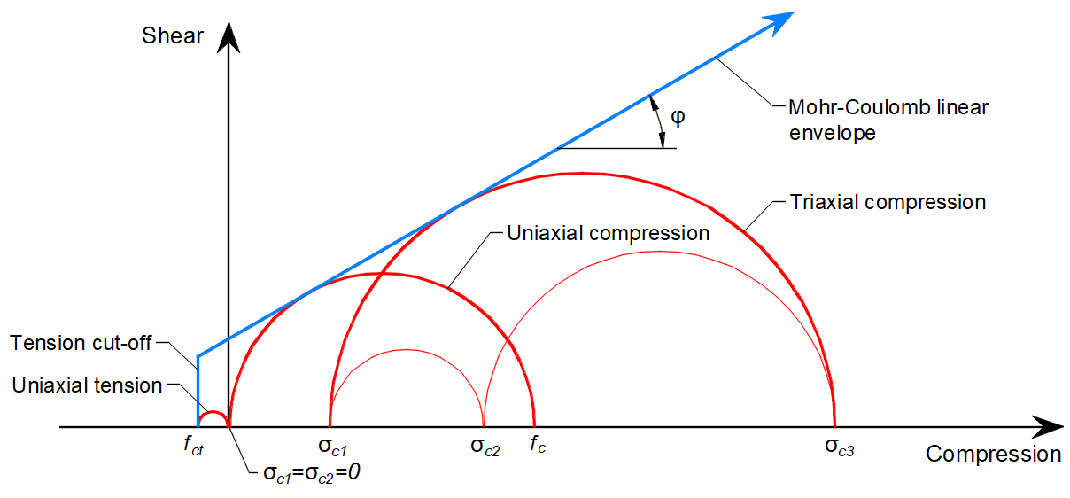
\[ \textsf{\textit{\footnotesize{Fig. 2\qquad Mohr's circles for concrete}}}\]
Where fc is concrete strength in compression, fct is concrete strength in tension, φ is the angle of internal friction, and σc1, σc3 are the principal stresses of concrete under triaxial compression.
It can be noticed that as the principal stress σc3 increases, the maximal possible difference between the values of σc3 and σc1, which we define as maximal σc,eq (see below), also increases.
In 3D CSFM as implemented in IDEA StatiCa Detail, the angle of internal friction is considered as φ = 0°, as shown in Figure 3.
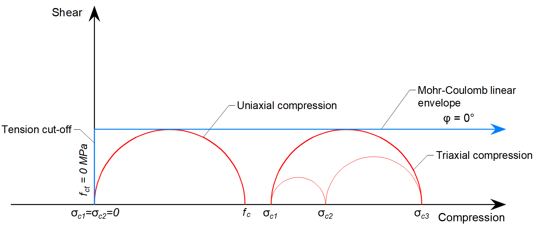
\[ \textsf{\textit{\footnotesize{Fig. 3\qquad Mohr's circles for concrete implemented in IDEA StatiCa Detail}}}\]
The practical consequence of this implementation is that the maximum difference between σc3 and σc1 is constant as σc3 increases.
Equivalent Principal Stress expresses the equivalent "damaging" uni-axial stress for a general tri-axial stress state.
\[\sigma_{c,eq} = \sigma_{c3} - \sigma_{c1}\]
The σc,eq value can, therefore, be directly compared with uniaxial strength limits according to codes.
Comparing Figure 2, where the real angle of internal friction is used, and Figure 3, which shows the Mohr-Coulomb theory's implementation with a zero angle of internal friction, it can be seen that the approach chosen for the calculations in the Detail application is very conservative for the assessment of the triaxial stress state. Note that the model with zero friction angle resembles the Tresca model, with tension cut-off.
Read more in Structural design of concrete 3D discontinuities in IDEA StatiCa Detail
Triaxial test – an active confinement example
In the example, we will simulate a triaxial test to explain how the triaxial pressure effect is implemented in 3D CSFM in IDEA StatiCa Detail. This will, therefore, be an example of active confinement. All calculations will be in characteristic values.
The model is of the solid block type with plan dimensions 1.0 x 1.0 m and a height of 3.0 m made of C30/37 concrete supported by a rigid surface support in the Z direction. Only for the sake of the stability of the analysis model, the X and Y directions are also included on the surface support with a neglectable stiffness value. The load is applied in two steps. In the first step, a hydrostatic pressure (σc,1 = σc,2 = σc,3) of 20 MPa is applied to the model. This high value, relative to the concrete strength, was chosen mainly to demonstrate the stability of the computational model.
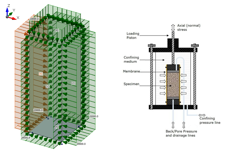
\[ \textsf{\textit{\footnotesize{Fig. 4\qquad Triaxial test setup - model, load, and boundary conditions}}}\]
After calculating the model, we get the value σc,eq = 0 MPa in the whole model. This corresponds to the previous definition of the implementation of the Mohr-Coulomb plasticity theory in Detail.
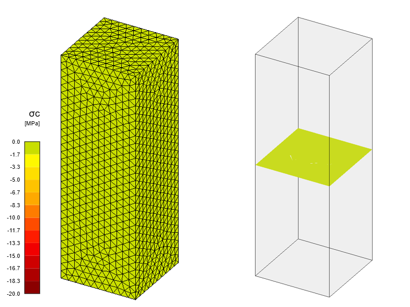
\[ \textsf{\textit{\footnotesize{Fig. 5\qquad Equivalent Principal Stress - first calculation step}}}\]
In the second step, a surface load of 50 MPa is applied to the upper surface of the model. Note that this load is higher than the considered axial compressive strength of concrete of 30 MPa. The objective of the test is to demonstrate that no load greater than the compressive strength of the concrete will be applied in this step. The calculation should, therefore, stop so that the applied load equals the resulting value of σc,eq.
Let us now look at the results. As expected, the calculation was stopped because the plastic strain criteria in the concrete, which is 5%, were exceeded.
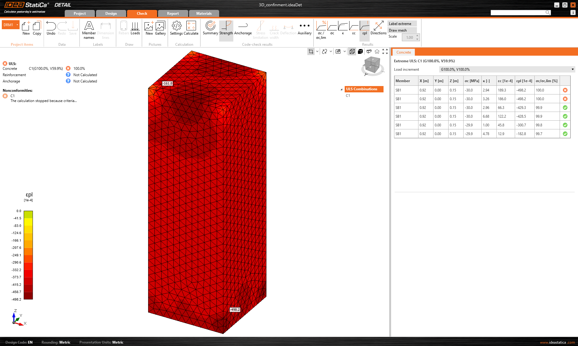
\[ \textsf{\textit{\footnotesize{Fig. 7\qquad Calculation result after the second step}}}\]
If we go through the results, we find that they match the assumptions defined above. This shows that the concrete model in Detail works correctly in terms of active confinement.
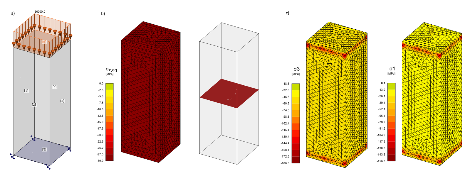
\[ \textsf{\textit{\footnotesize{Fig. 7\qquad a) Applied load in step 2; b) Equivalent principal stress; c) Principal stresses σc,3 a σc,1}}}\]
The stress peaks that can be observed at the top and bottom surfaces are caused by the way of applying surface load and surface support to the edges of the mesh from tetrahedral elements with nodal rotations. And also the fact that the maximum nodal values from adjacent finite elements are always displayed in the Detail application. However, the subject of this article is not the specification of this method, so we will not pursue it further.
ABAQUS verification
In the next step, we will look at a comparison with models created in ABAQUS, where Mohr-Coulomb plasticity theory is also used to define concrete. We will compare the results from Detail with a real concrete model with an internal friction angle of 30°. Thus, we demonstrate the conservativeness of the approach in 3D CSFM.
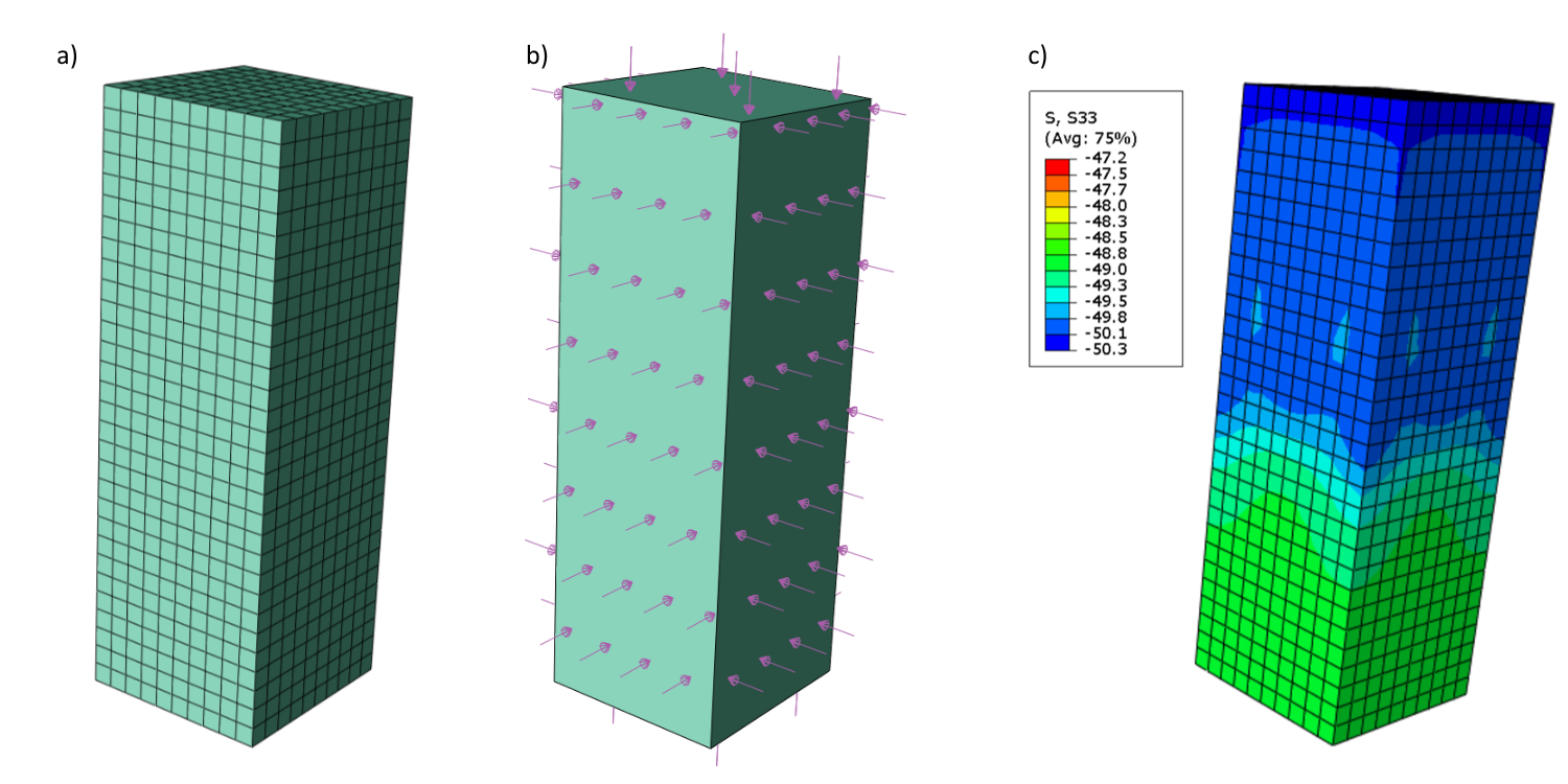
\[ \textsf{\textit{\footnotesize{Fig. 7\qquad ABAQUS model: a) Concrete mesh 2; b) Load definition; c) Principal stresses σc,3}}}\]
In ABAQUS, we created a model similar to the model in Detail. The definitions of material, boundary conditions, and loads are identical. On the other hand, the concrete mesh is simplified. The results for two calculations, one using φ = 0°; c = 15 MPa and the second φ = 30°; c = 8.65 MPa, are shown in the graph below as well as the comparison with other angles of internal friction φ = 10°, 20°, 40°.
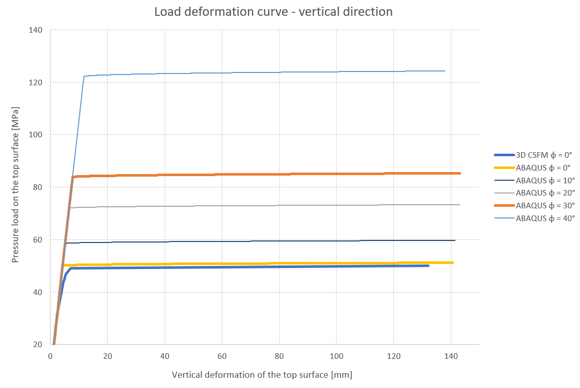
\[ \textsf{\textit{\footnotesize{Fig. 7\qquad Comparison of 3D CSFM, an ABAQUS model with various angles of internal friction }}}\]
The graph shows the match between the 3D CSFM and ABAQUS models for φ = 0°. It is also clearly illustrated that the simplifications in the definition of the concrete material in 3D CSFM (the horizontal plastic branch of the stress-strain diagram and horizontal Mohr-Coulomb linear envelope), which lead to both better clarity and, more importantly, faster calculation, also lead, at least in terms of tri-axial stress, to conservative results.
As a last point, it is worth mentioning that if we consider a hydrostatic stress higher than 20 MPa, the difference between models φ = 0° and other angles would be even greater.
Conclusion
It was shown and explained that the calculation in 3D CSFM is consistent with the assumptions reported in the Theoretical Background. This was verified by comparison with ABAQUS models and the conservatism of the 3D CSFM approach to the tri-axial stress phenomenon was demonstrated.