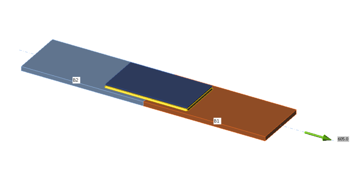
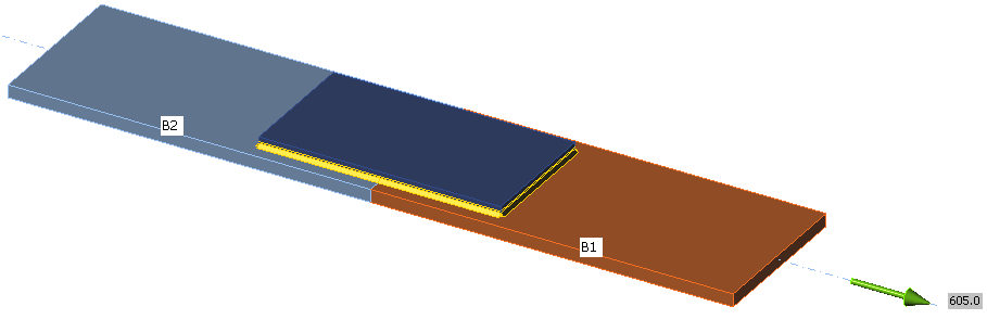
Welded splice connection (AISC)
Sub-code: LRFD
Type of connection: Concentrically loaded multi-oriented weld group
Unit system: Metric
Designed acc. to: AISC 360-16
Investigated: Welds
Plate Materials: Plate and column – ASTM A572 – Gr. 50
Welds: Leg size = 3 mm, electrode E70XX
Geometry:
Member thickness: 16 mm
Splice thickness: 12 mm
Applied forces:
Simple welded connections are loaded by tension to be utilized at 100 %. Welds are designed to be the weakest component.
Procedure:
Concentrically loaded splice connection with weld groups consisting of elements with a uniform leg size that are oriented both longitudinally and transversely to the direction of applied load is loaded by tension and is designed so that welds fail first. The joint is loaded for the weld to be utilized at 100 % and the load is compared to the weld resistance according to AISC 360 16 – J.2.4.
Manual calculation
The combined strength of the fillet group is determined according to AISC 360-16 – J.2.4 (2).
Base metal strength does not have to be evaluated in case of use of matching electrodes but it is shown here for verification.
An example of a splice connection with the length of longitudinal welds 150 mm and the length of transverse welds 160 mm is shown in the table below:
Comparison:
The results of both IDEA StatiCa Connection design and computation according to AISC 360-16 give nearly identical values in case of weld metal strength (98–101%). With consideration of base metal check, IDEA is slightly conservative (93–94%). Using finite element analysis and the approach of checking the most stressed element of the weld, there is no need for any manual reduction of weld resistance due to weld orientation.


