Concrete column - Fire analysis (EN)
1 New project
Open IDEA StatiCa and select the Member application.
Create a new project (1), type its name, and select a folder where it will be saved. Then, choose the project type Concrete (2), turn on the Fire design (3), and the type of Topology (4). Define the high of the column to 8 m (5). Click on Arrow (6) to set the cross-section. Select the rectangle cross-section (7). Chance the dimensions (8) and click on the OK button (9). Finally, click on Create project (10).
2 Design
The column is now created with related members. Delete all Related members.
Set the boundary conditions according to the enclosed figure. You have created the boundary conditions which are representing the simply supported column.
The next step is to define the reinforcement layout. Select the analyzed member AM1 (1) and click on the Rebar assembly (2) button. Then input the reinforcement (3) by using the template. The values are set, check them (4) and confirm OK (5,6).
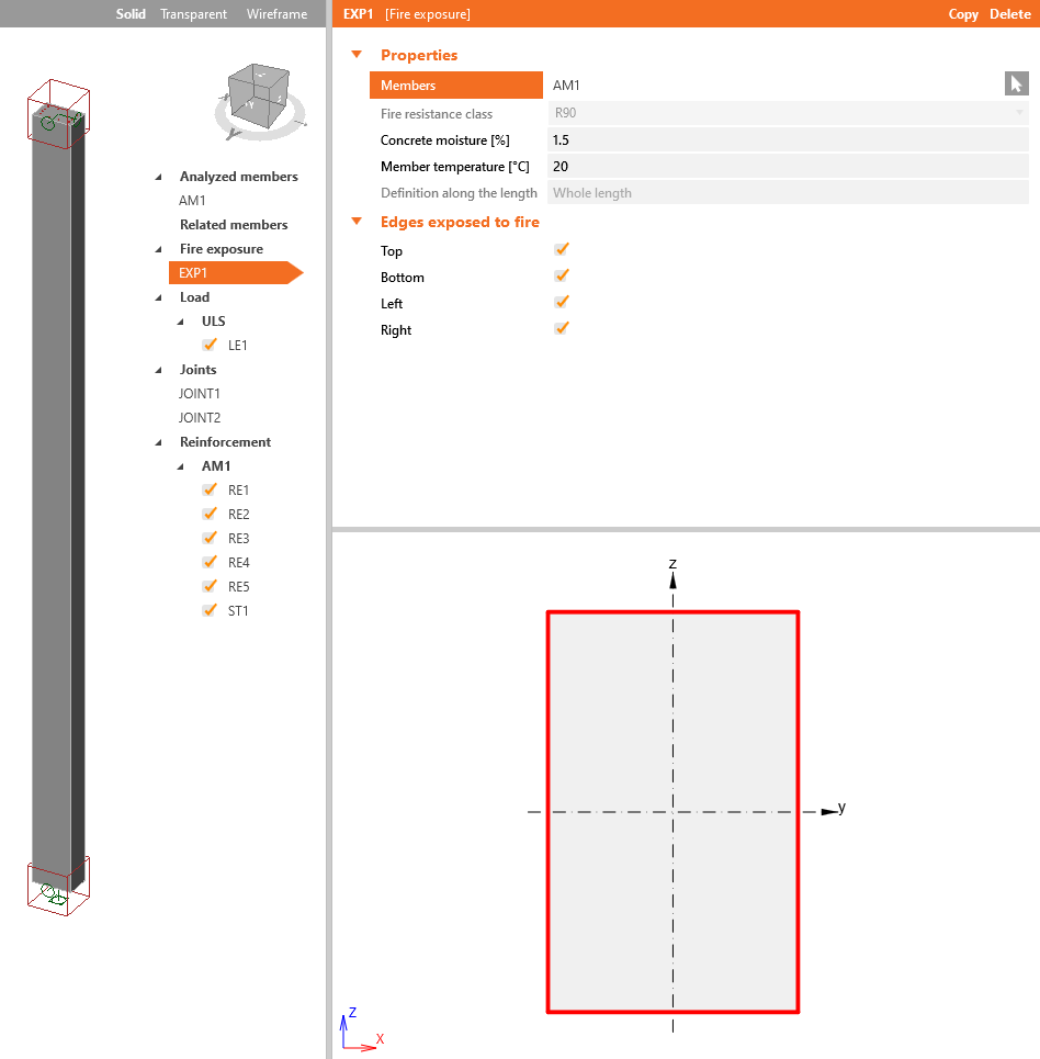
The Fire exposure data serves for adding initial conditions for thermal analysis. Start with using right-click button on the Fire exposure-->Add fire exposure.
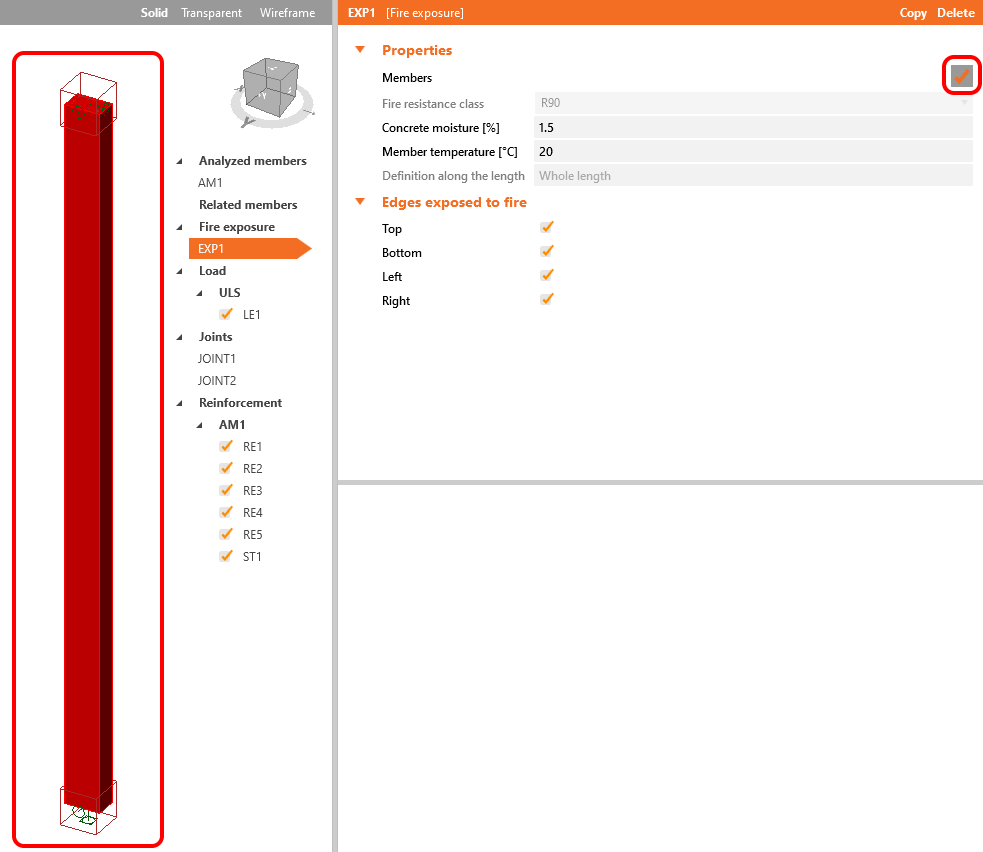
Click on the Cursor button in the Fire exposure Properties. It will allow you to start the selection. Select the whole column, and don't forget to confirm the selection.
The red lines around the rectangle introduce the edges exposed to fire. Consider that all edges will be subjected to fire load. Let all the ticks on.
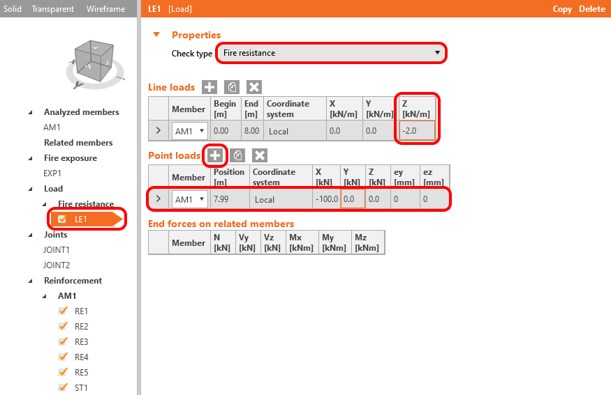
The load used for fire design, according to EN 1992-1, can be considered as 70% of ULS. The point and line load represent the fire design load.
3 Check
The model is done. You can check the Material degradation tables by selecting the Fire design--> Material degradation-->Concrete or Reinforcement.
Leave the tables as they are, click OK and Save the settings.
Move to the tab Check-->GMNA-->Calculate. This procedure starts MNA - Materially non-linear analysis.
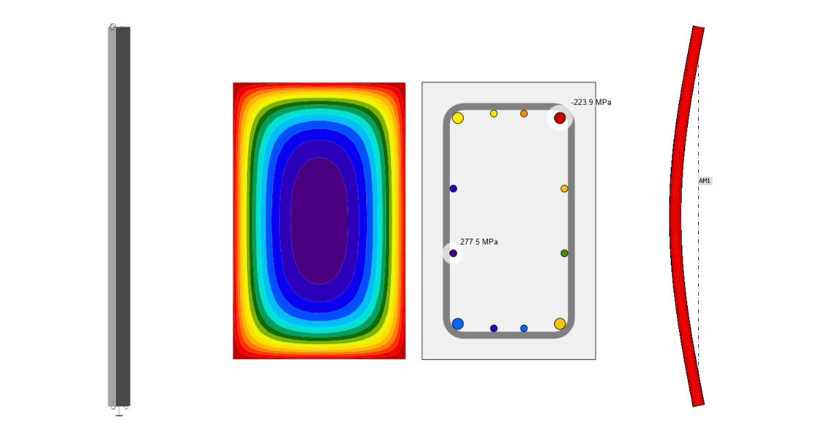
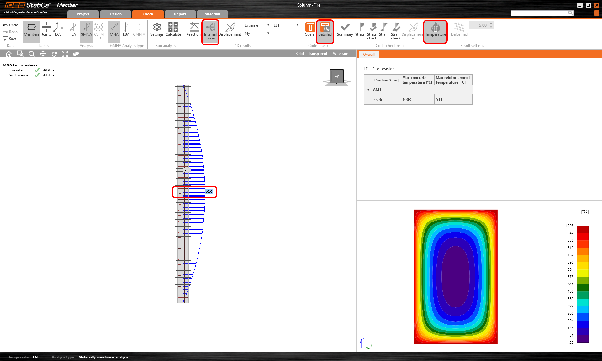
Once the calculation is completed. You can check the results. To do that, click on Detailed and Temperature. Then you have to choose the critical section. You can also check the internal forces. Click on the Internal forces button.
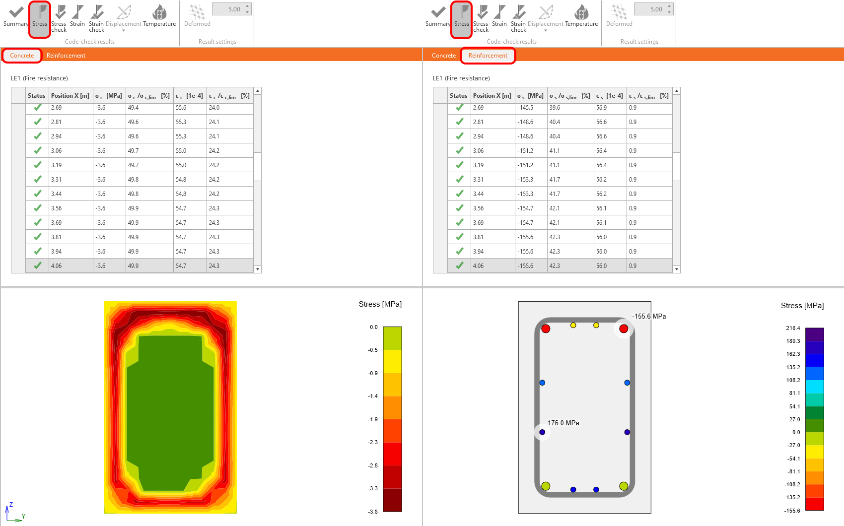
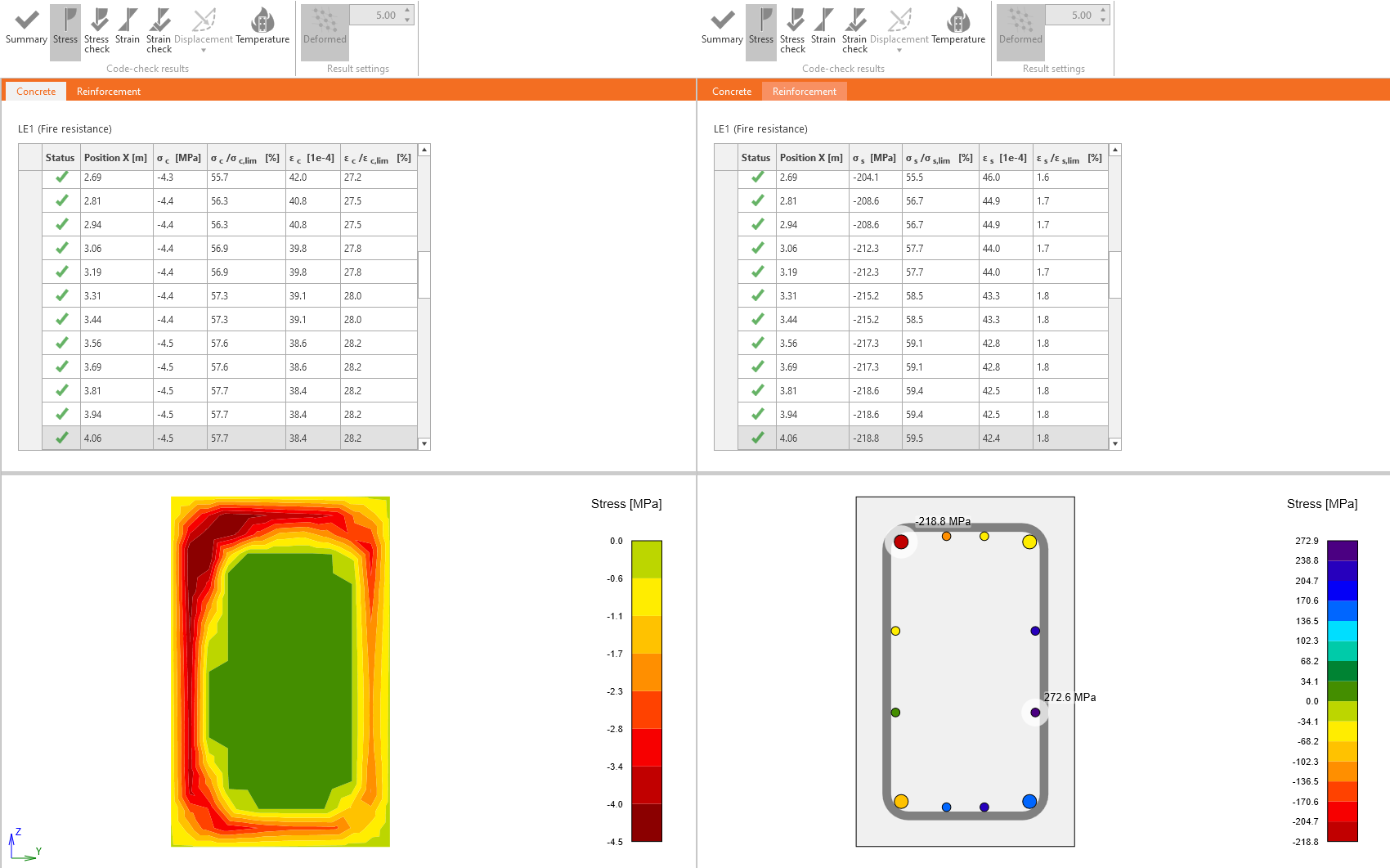
You can also check the Stress in the Concrete or Reinforcement.
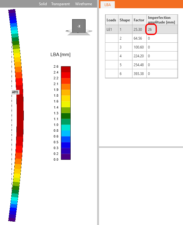
Run the LBA - Linear buckling analysis.
When the calculation is completed, set the Imperfection amplitude. The value of the amplitude is calculated according to EN 1992-1-1 article 5.2 (9).
\[{{e}_{i}}={{l}_{0}}/400=8000/400=20mm\]
Read the following article to learn how to set it including the additional amplitude caused by creep.
The amplitude including the creep effect is 26 mm.
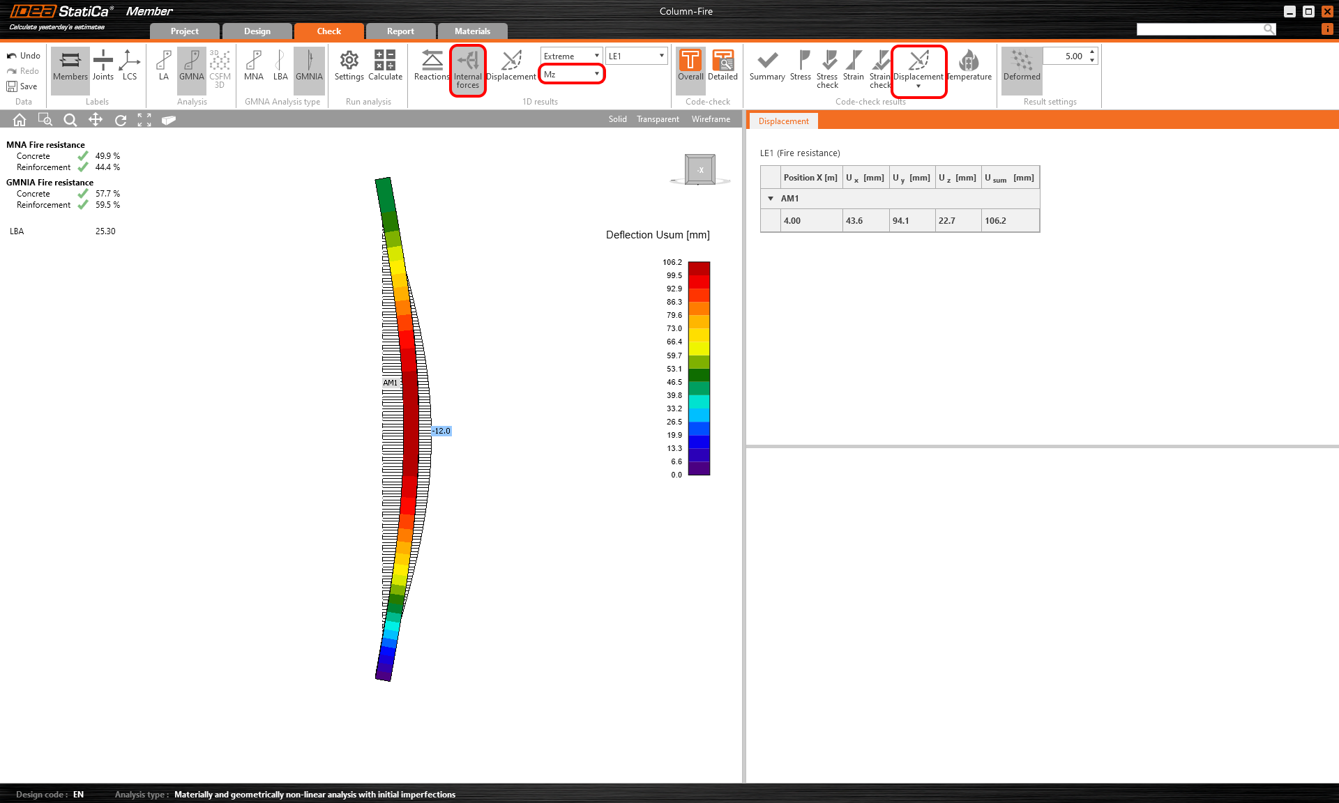
Start GMNIA - Geometrically and materially non-linear analysis with imperfections.
That was the last analysis type. You can check the results as well as in the MNA. Due to the second-order effect, you can see increased bending moments and deformations.
You can check and compare the stresses in concrete and in reinforcement. Don't forget to click on Detailed and select the critical cross-section.
3 Report
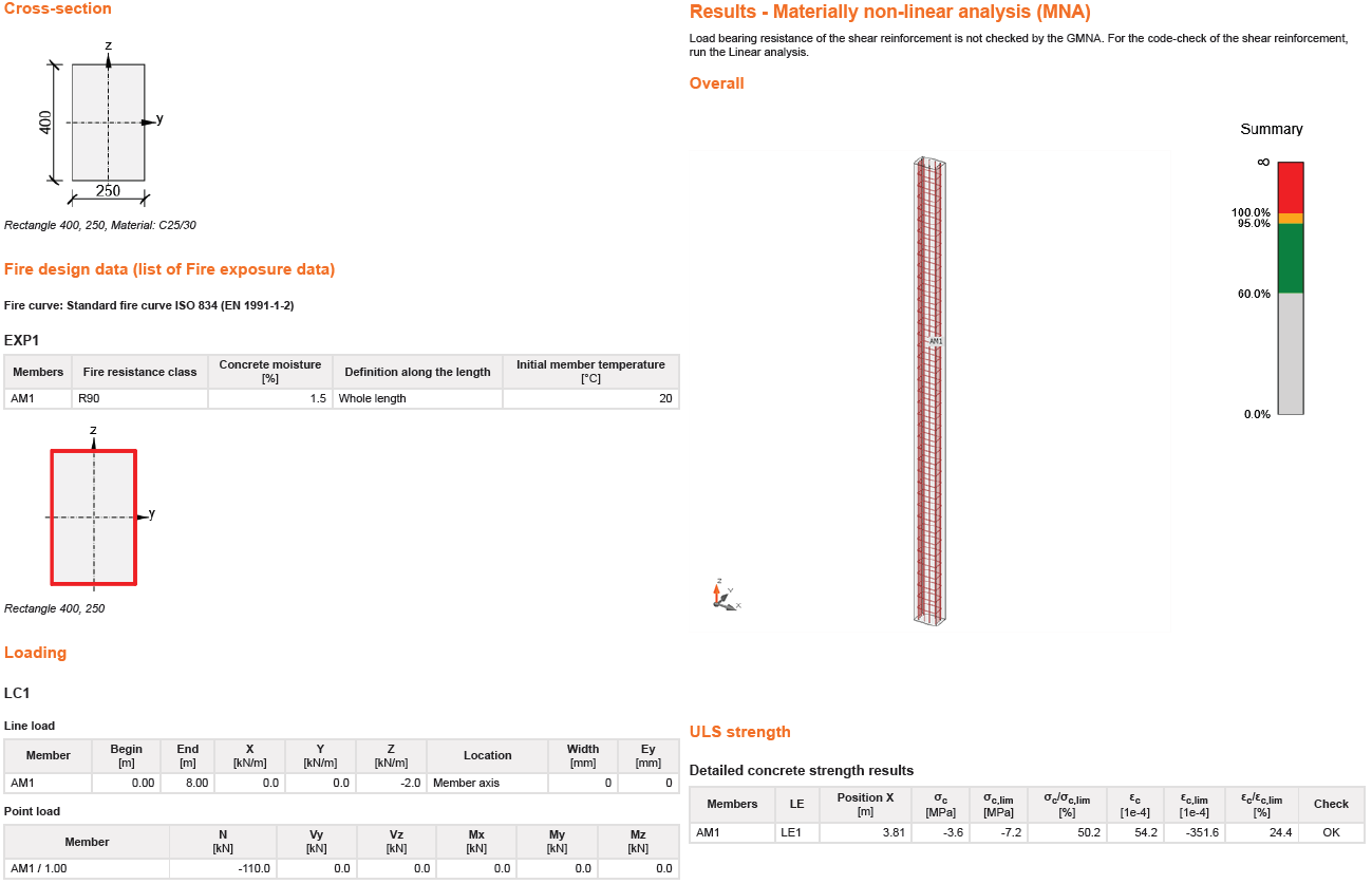
Go to the report tab. Here the report can be printed.


