Learning Module: Prying action
Connection design can be difficult to teach, given the detailed nature of the topic and the fundamentally three-dimensional behavior of most connections. However, connections are critically important, and lessons learned in the study of connection design, including load path and identification and evaluation of failure modes, are general and applicable to structural design broadly. IDEA StatiCa uses a rigorous nonlinear analysis model and has an easy-to-use interface with a three-dimensional display of results (e.g., deformed shape, stress, plastic strain) and thus is well suited for the exploration of the behavior of structural steel connections. Building on these strengths, a suite of guided exercises that use IDEA StatiCa as a virtual laboratory to help students learn about concepts in structural steel connection behavior and design was developed. These learning modules were primarily targeted to advanced undergraduate and graduate students but were made suitable for practicing engineers as well. The learning modules were developed by Associate Professor Mark D. Denavit from the University of Tennessee, Knoxville.
Learning Objective
After performing this exercise, the learner should be able to describe prying action, the parameters that affect it, and how it affects the design of structural steel connections.
Background
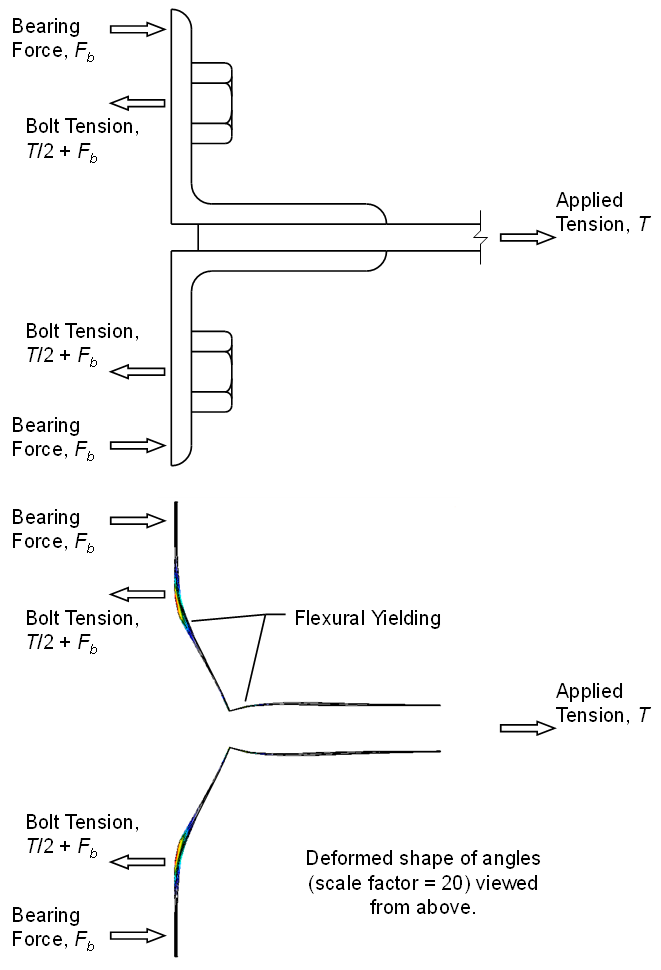
Bolts in tension can be subjected to greater force than expected due to a phenomenon known as prying action.
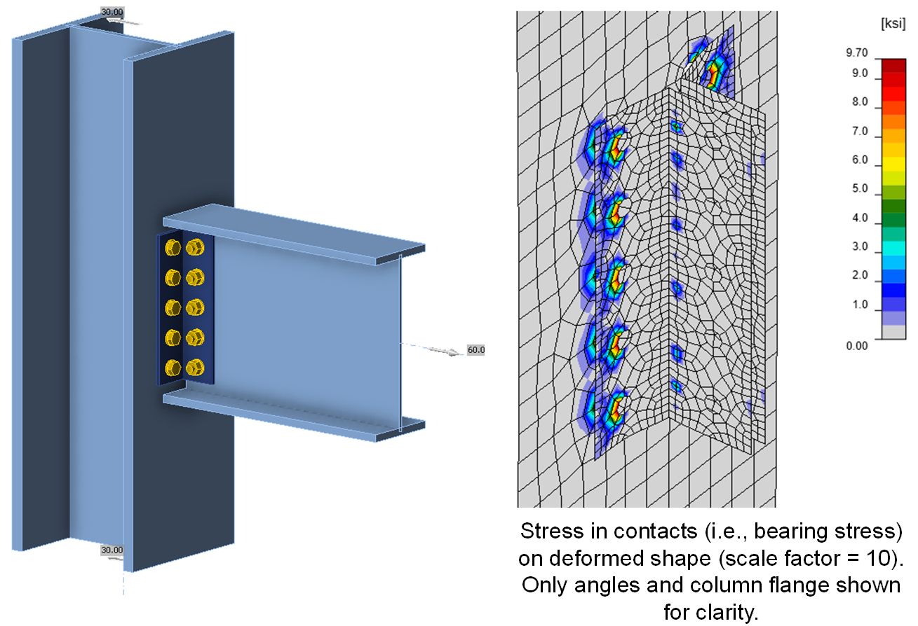
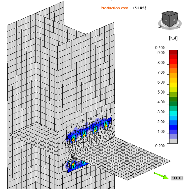
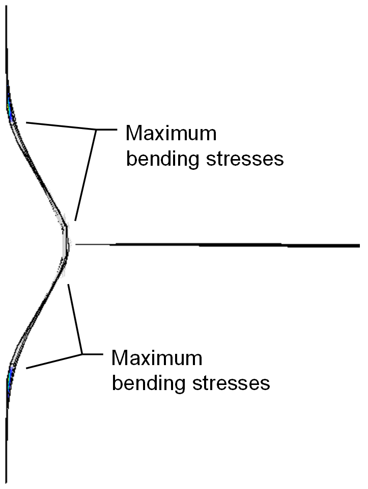
While not limited to T-stubs and angles, prying action is most clearly identified and evaluated with these components. Consider the all-bolted double-angle connection shown in the figure below. The beam, acting as a chord or collector, is subject to 60 kips of tension (for simplicity, shear in the beam is neglected). 5 bolts connect each angle to the column flange for a total of 10 bolts between the angles and the column flange. Based on a simple analysis, one may expect the tension in each bolt to be 60 kips/10 bolts = 6 kips per bolt. However, the actual tension force is greater, about 14 kips per bolt for the connection shown below, because the toes of the angles are bearing on the column flange and the bearing force adds to the bolt tension.
The magnitude of the bearing force depends on the stiffness and strength of the connected elements and bolts.
- If the angles are very thin, they will yield both near the heel and near the bolt line, and the strength of the angles will control even when considering additional tension in the bolts due to prying action. The Eurocode describes this as failure mode 1.
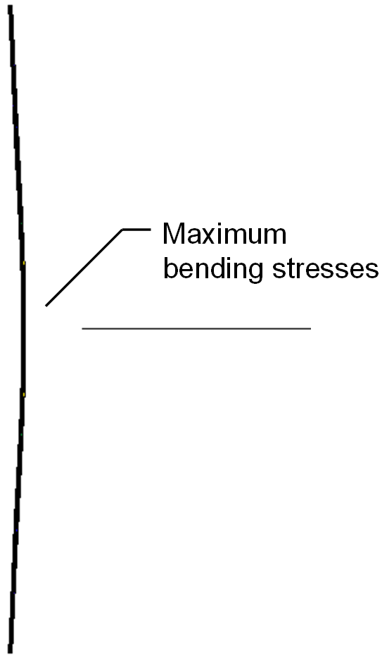
- If the angles are very thick, the leg will not bend enough to overcome the elongation of the bolt, and the toe will not contact the column flange. In this case, there is no prying action, the strength of the bolts will control, and a simple analysis is sufficient to estimate the force in the bolts. The Eurocode describes this as Mode 3.
- For angle thicknesses between these extremes, the flexural strength of the angles and the tensile strength of the bolts can control simultaneously.
In Eurocode 3 (CEN, 2005), these different behaviors are called “Mode 1: Complete yielding of the flange”; “Mode 2: Bolt failure with yielding of the flange”; and “Mode 3: Bolt failure” and correspond to thin, intermediate, and thick connecting elements, respectively.
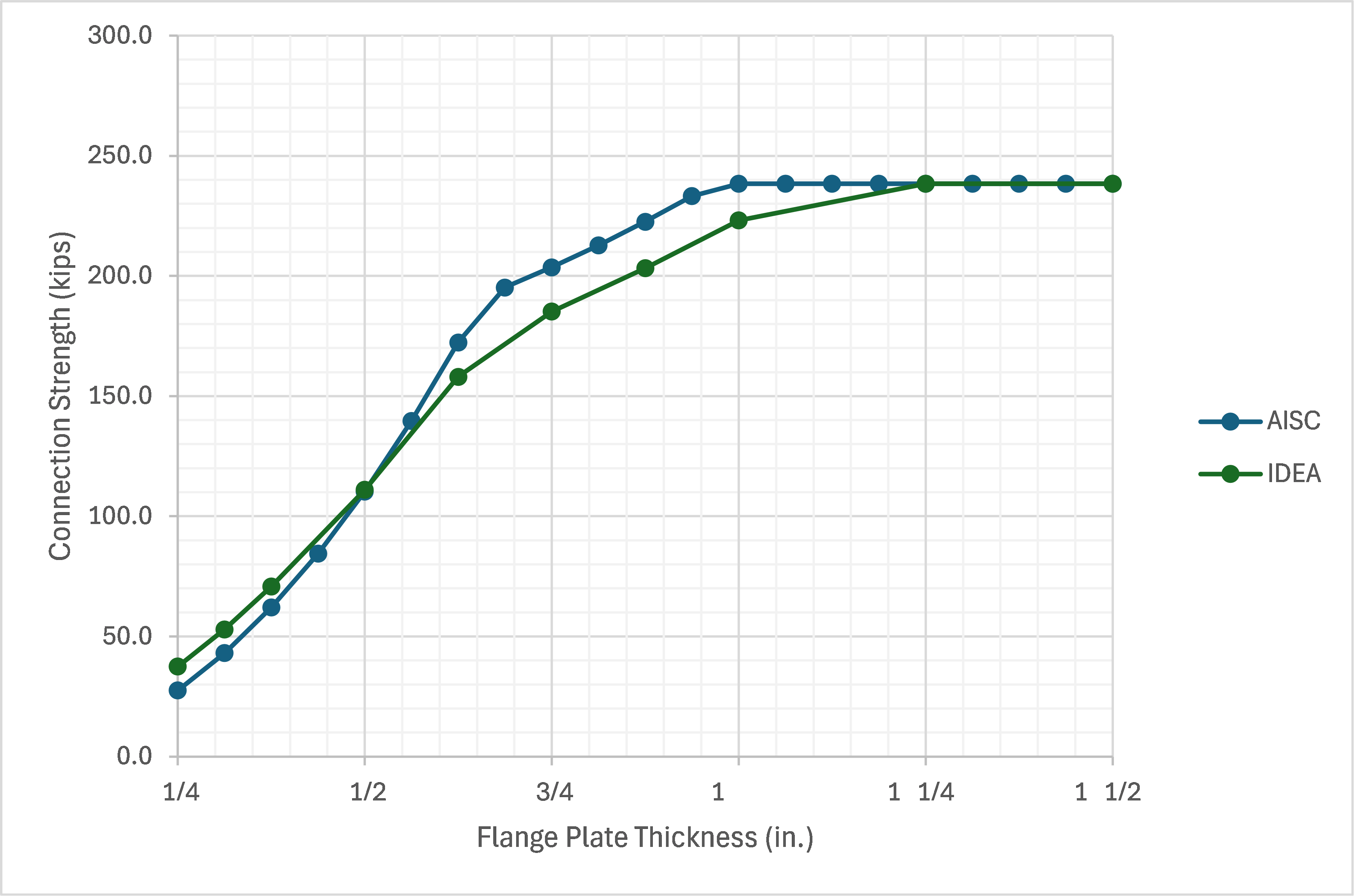
Equations to assess prying action are presented in AISC Manual Part 9 (AISC, 2023). These equations can be used to efficiently assess prying action, but they use abstracted parameters that obscure the physical behavior. This exercise is intended to help develop physical intuition on prying action.
Connection
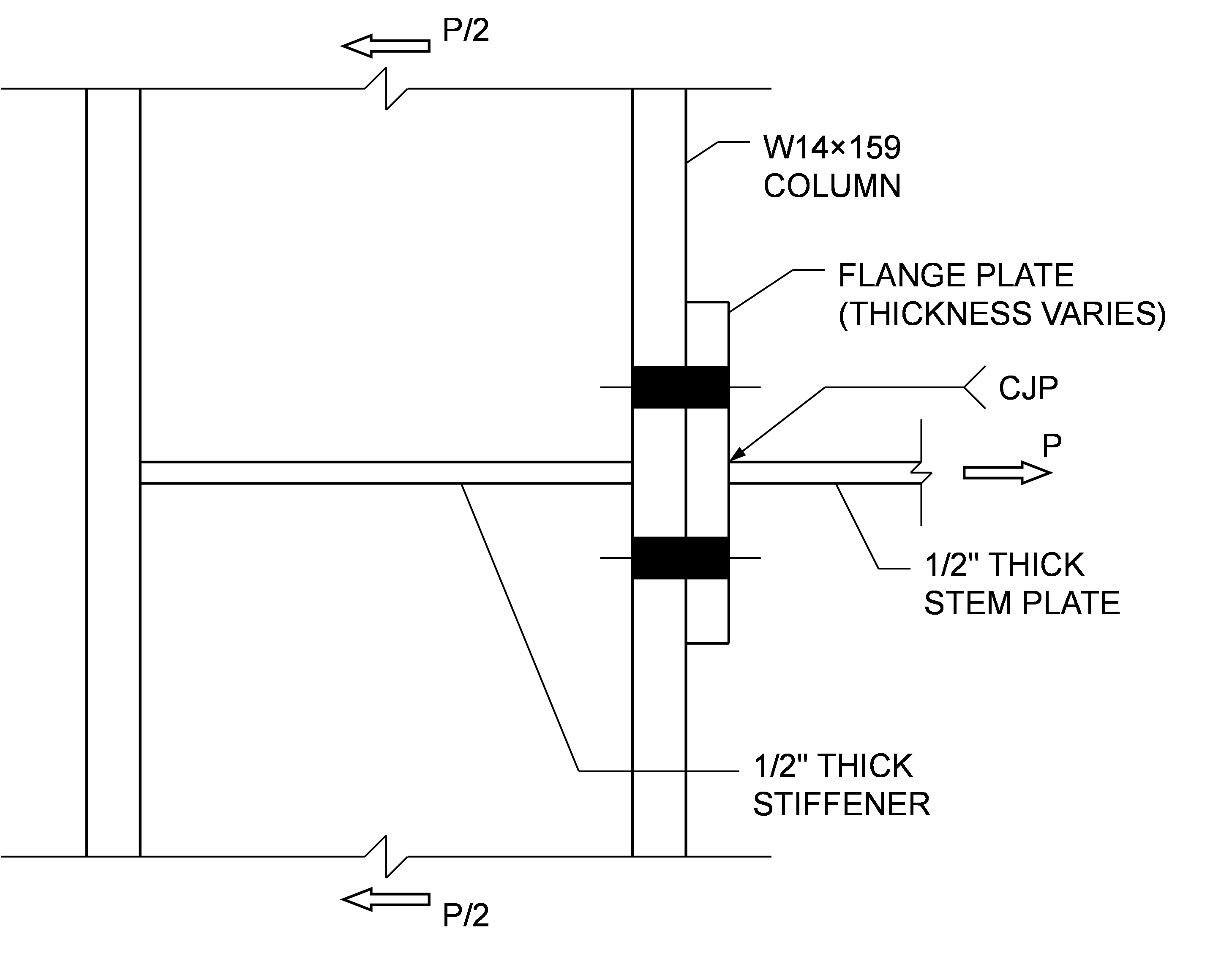
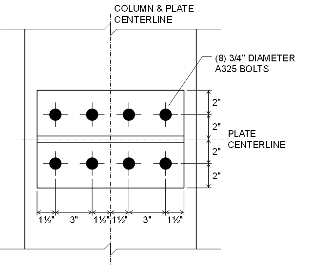
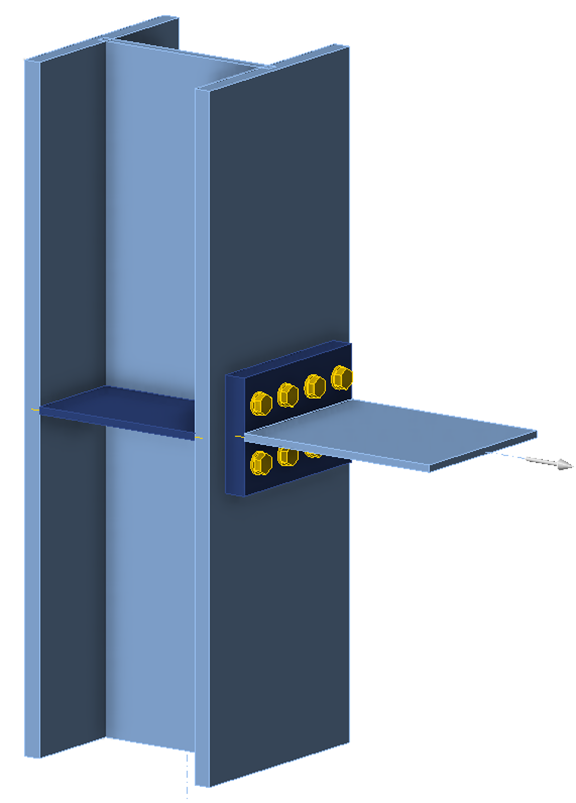
The connection examined in this exercise is inspired by the double-tee moment connection but consists only of the column and the tension T-stub (the beam and compression T-stub are not included).
The T-stub is made of two plates to allow easy variation of the geometry during the exercise. The plates are butt welded for simplicity. The column is relatively large and provided with a stiffener to form a firm base for the T-stub – prying action can also occur if the column flange bends and contacts the T-stub. The column is modeled in IDEA StatiCa as continuous and with a N-Vy-Mz model type so that the applied tension is resisted by shear at the top and bottom of the column and entry of the shear force is not necessary (i.e., unbalanced forces are okay).
Procedure
The procedure for this exercise assumes that the learner has a working knowledge of how to use IDEA StatiCa (e.g., how to navigate the software, define and edit operations, perform analyses, and look up results). Guidance for how to develop such knowledge is available on the IDEA StatiCa website (https://www.ideastatica.com/).
Retrieve the IDEA StatiCa file for the example connection provided with this exercise. Open the file in IDEA StatiCa. To perform the exercise, follow the narrative, complete the tasks, and answer the questions.
Complete the table shown below by determining the maximum force that the connection can support for a variety flange plate thickness, then recording that force along with the maximum plastic strain and maximum bolt utilization at that force.
| Flange Plate Thickness (in.) | Maximum Force (kips) | Maximum Plastic Strain (%) | Maximum Bolt Utilization (%) |
| 1/4 | |||
| 5/16 | 53.0 | 5.0 | 76.8 |
| 3/8 | 70.8 | 4.9 | 77.7 |
| 1/2 | |||
| 5/8 | 158.1 | 5.0 | 91.3 |
| 3/4 | 185.2 | 4.9 | 99.9 |
| 7/8 | |||
| 1 | 223.2 | 5.0 | 97.9 |
| 1 1/4 | 238.4 | 0.1 | 99.9 |
| 1 1/2 |
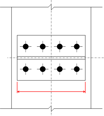
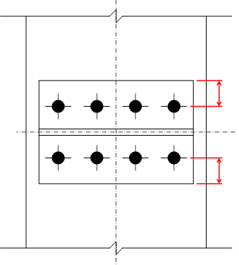
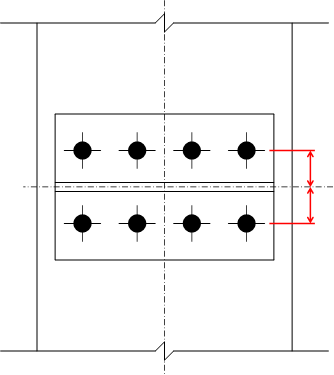
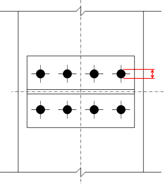
11. Does the strength of the connection increase, decrease, or stay the same when the following dimensions are increased? Consider how the answer might be different for different flange plate thicknesses.
References
AISC. (2022). Seismic Provisions for Structural Steel Buildings. American Institute of Steel Construction, Chicago, Illinois.
CEN. (2005). Eurocode 3: Design of steel structures - Part 1-8: Design of joints. European Committee for Standardization, Brussels, Belgium.


