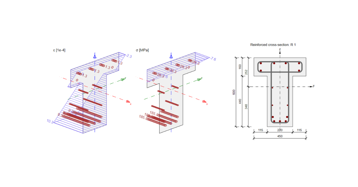
SLS results in RCS - Stress Limitation, Crack Width, Detailing
There are four tabs focused on SLS results in the application.
- Overall results
- Stress Limitation
- Crack Width
- Detailing
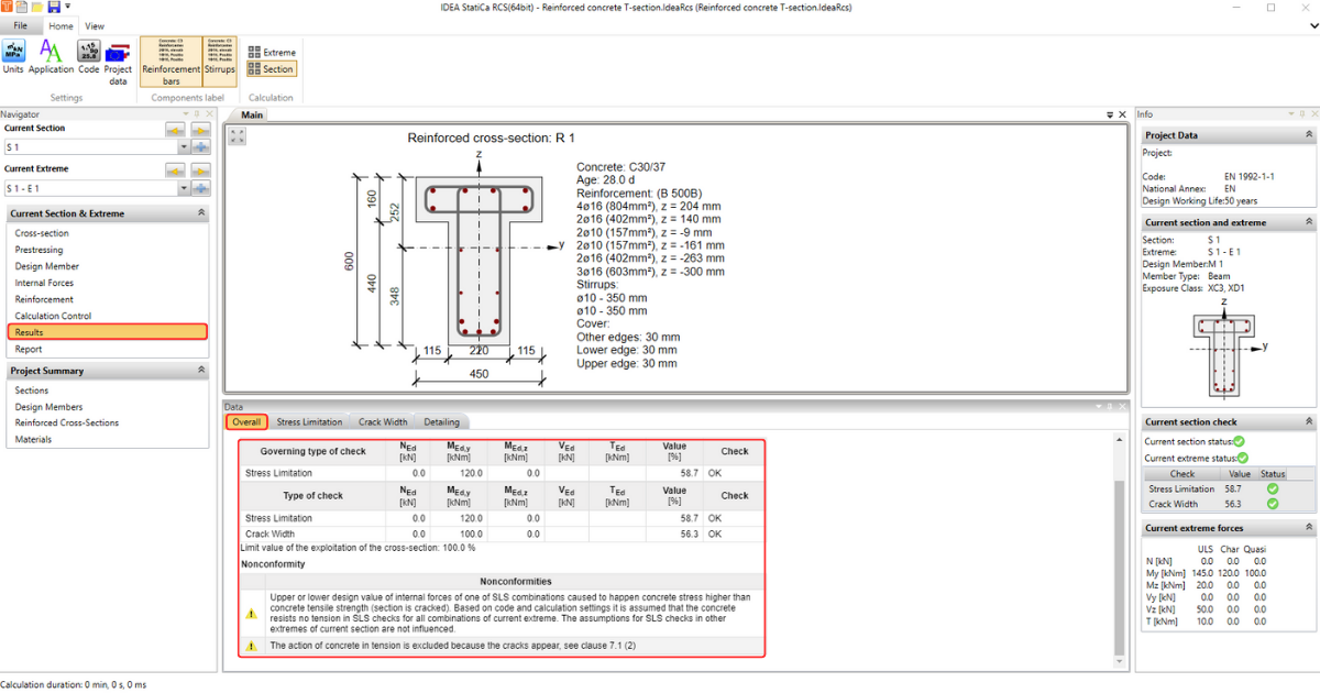
In the first tab, you can find a brief overview of the Overall results. You will see only the results of the analysis you selected using calculation control.
The rest of the tabs are dedicated to individual checks. But before looking at them, we need to understand the assumptions of the calculation. Therefore please go through the article: Calculation Assumptions for SLS. With this knowledge, we can then continue and go through the individual results step by step.
Stress Limitation
First, there is Stress Limitation Check. This calculation provides a comparison of the calculated stress with limit values according to Eurocode. How specific values are obtained and what basic cases (in terms of stress limit) we solve, you can find in the article: Stress Limitation Check.
We'll explore how to work with the results and how to eventually influence them as soon as we've got some idea of the layout and display options.
Layout
Check to Top Ribbon, the part Setting is dedicated to Code and Project Data. It is the same for all the steps of the workflow.
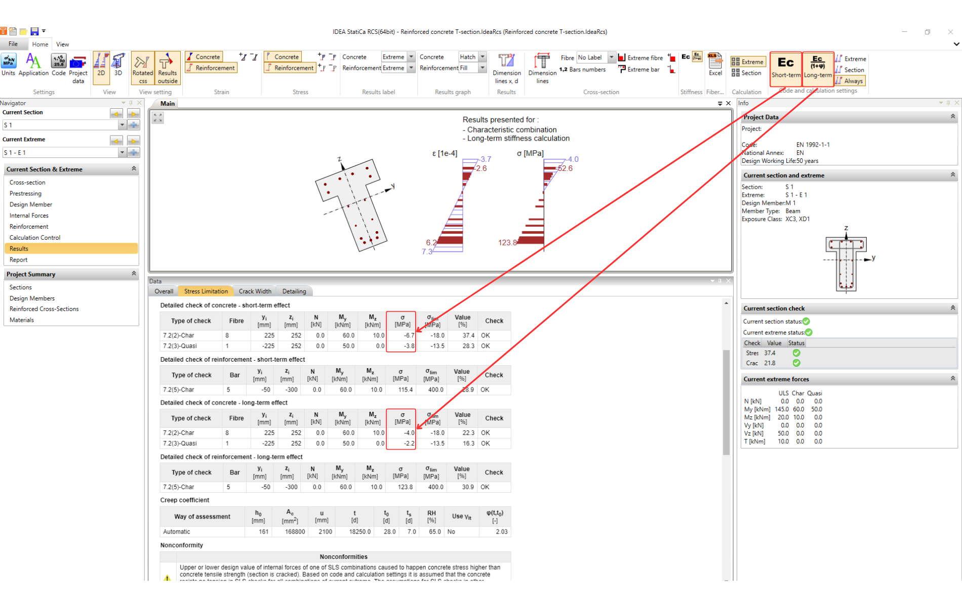
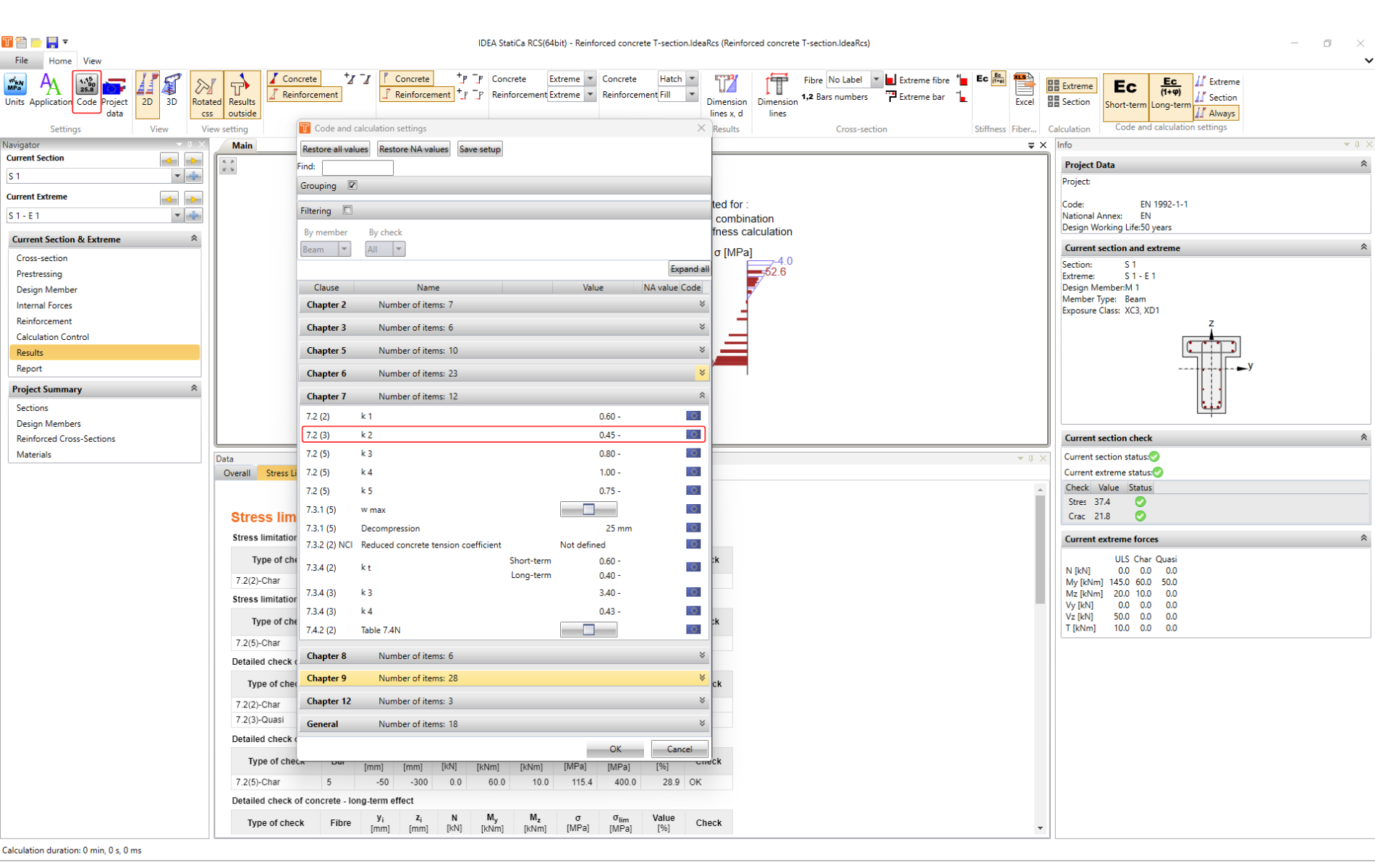
The following parts are already different. Notice the figure below, there are marked options for adjusting the graphical presentation of the result:
Options Description:
- Option to switch between 2D and 3D view. For the 2D view, we can decide if we want to see a rotated cross-section or the result inside/outside of the cross-section.
- The tab is used to switch off/on the strain diagram for the concrete and reinforcement section and its size adjustments.
- The tab is used to switch off/on the stress diagram for the concrete and reinforcement section and its size adjustments.
- The option to display extreme values of the diagrams, all or none.
- As next, we can modify the filling of the diagram.
- The following two buttons allow us to switch on/off dimension lines.
- The last part is dedicated to the cross-section. We have the option to display bar and fibres numbers and modify their position. We can also display Extreme bar and fibre.
Calculation
The rest buttons from the top ribbon are related to the calculation itself.
For the stress limitation, we have 4 code checks, as mentioned at the beginning of the chapter. The first two checks, according to 7.2 (2) and 7.2 (3), are done for both cases: With or without the influence of the long-term effects (rheology of concrete).
For the short-term effects, the modulus of elasticity Ecm is used.
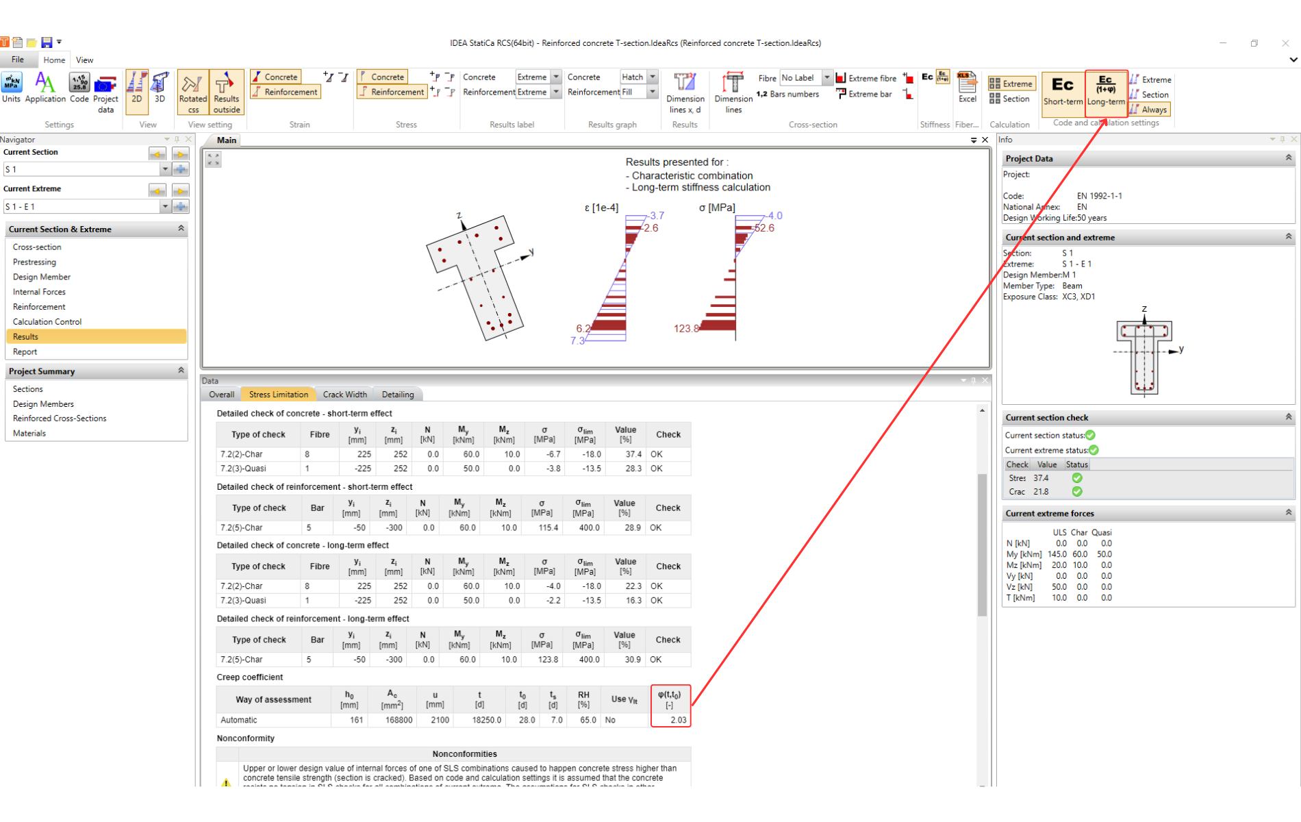
For the long-term effects, the effective modulus of elasticity Ec,eff = Ecm/(1+φ) is used. Where φ is the creep factor.
The long-term effects are thus included in the creep.
The creep factor can be Calculated by the software (default option) or can be set manually in Design Member. Please be aware that in the RCS, the linear calculation is used for the creep factor.
The code-check is provided by a comparison of the calculated stress in the concrete and in reinforcement with limit values according to EN 1992-1-1 7.2.
Tip for advanced users
There is an option how to influence the results when the limit is exceeded for 7.2 (3). It is allowed to consider a higher value of the k2 factor when the nonlinear calculation of the creep factor is considered.
You can change the value of k2 in the Code setting:
But remember that it is necessary to determine the creep factor more precisely.
Let's summarize the options we have:
- The creep coefficient is Calculated by software using linear calculation. Then factor k2 = 0.45 (set by default) has to be used.
- The creep coefficient is set as User input. When considering the nonlinear creep, we can increase the factor to k2 = 0.6.
Crack Width
If the concrete stress is higher than the concrete tensile strength, the section is considered as a cracked one. And the next code check from the SLS check is the crack width.
See the Theoretical background - Cracks for the theory, assumptions, and how the crack width calculation is implemented in RCS.
For complete understanding, it is also recommended to read the following article: Crack width check of cross-sections with a large concrete cover.
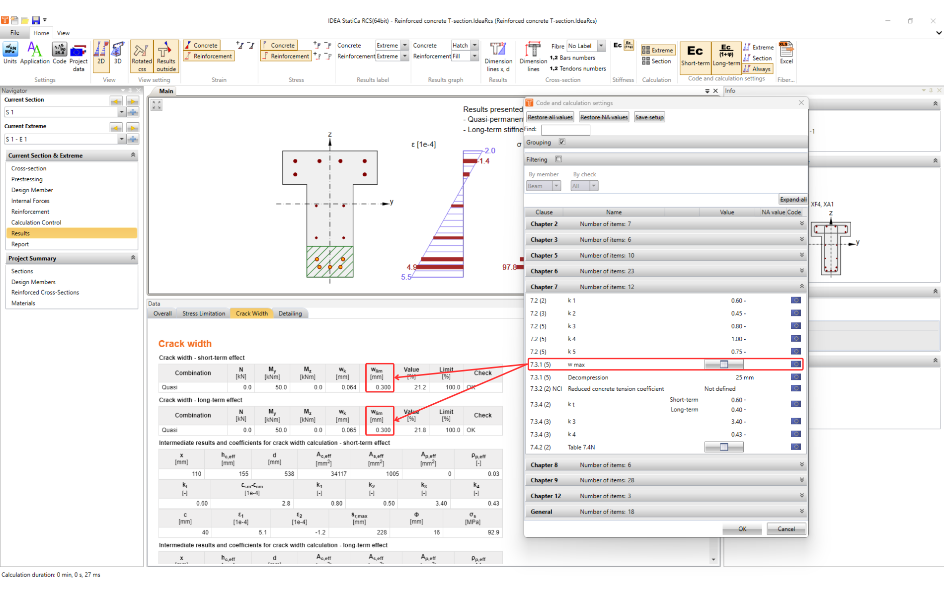
The code-check of the crack width is provided by comparing the calculated width wk with the width wlim according to 7.3.1 (5).
Implemented limits can be found in the Code setting.
Detailing
Detailing is the last code-check from the SLS checks.
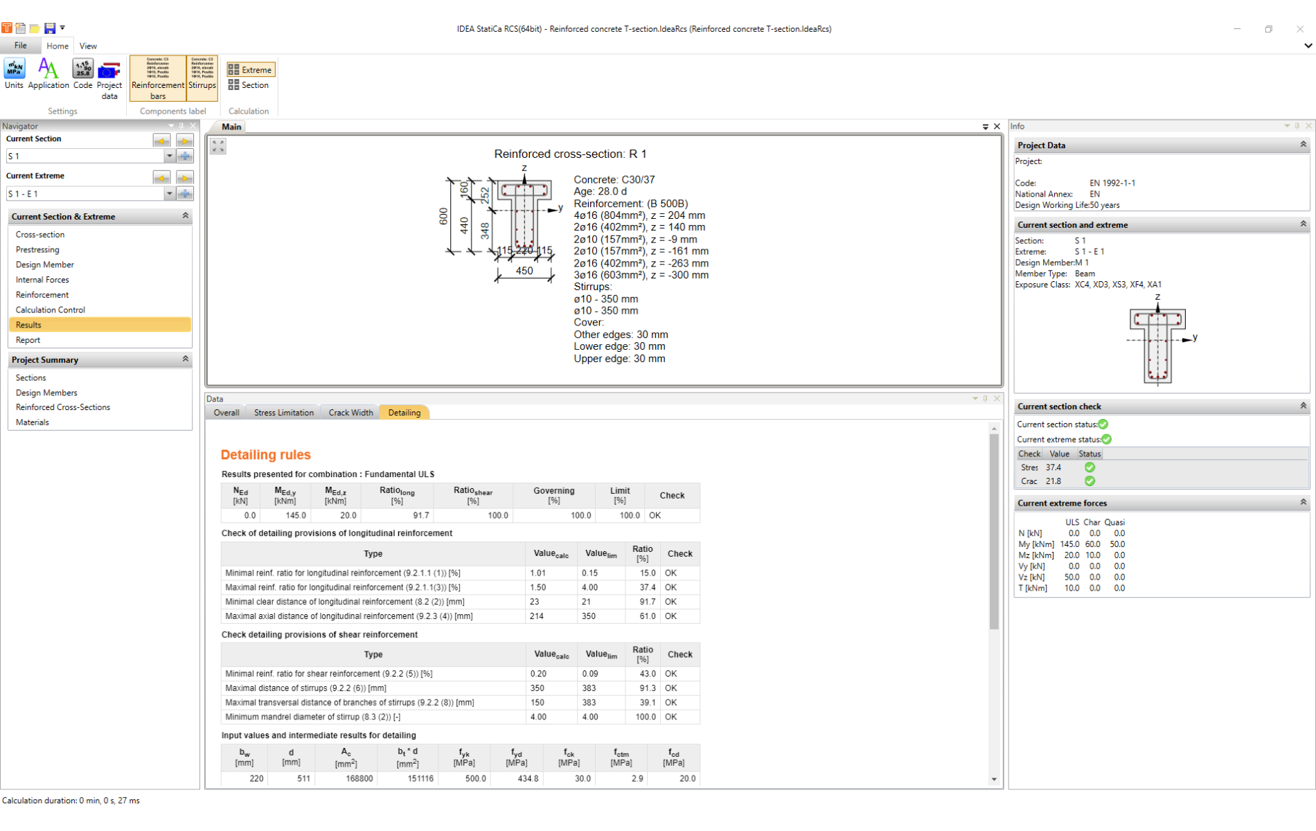
The internal forces for which the check is made are listed at the beginning of the table.
The following are the conditions of the check. All are taken from the Eurocode. The reference to the specific article is always given next to the title.
This is followed by information on the values used in the calculation based on the input data.
Tip for advanced users
It may happen that in order to speed up the design, we enter into RCS the simplified scheme of the reinforcement. In this case, we recommend switching Detailing off in Calculation Control and checking it manually according to more detailed drawings.


