Single tool for complete base plate workflow
Current practice for anchor reinforcement
The concrete breakout failure happens for several reasons:
- Small concrete area below the base plate: Pedestal, strip foundation, piers, base plate near the concrete edge
- Limited anchor embedment
- High moment, shear, or uplift forces in the base plate due to heavy structures
- Load combinations of the above forces
In current engineering practice, anchors are designed assuming an unreinforced concrete section. The standard equations used in ACI-318 Chapter 17 were developed based on the concrete capacity design (CCD). However, ACI 318 allows the use of anchor reinforcement to resist breakout forces when geometric constraints prevent increasing the concrete breakout capacity.
In ACI 318, three different categories of concrete reinforcement may be present in a foundation:
- Foundation reinforcement: Reinforcement designed to resist bending forces in the foundation, i.e. piers
- Anchor reinforcement: Serves as an alternate approach to using the concrete breakout strength equations provided in ACI 318. Designed to resist the required strength of the base connection
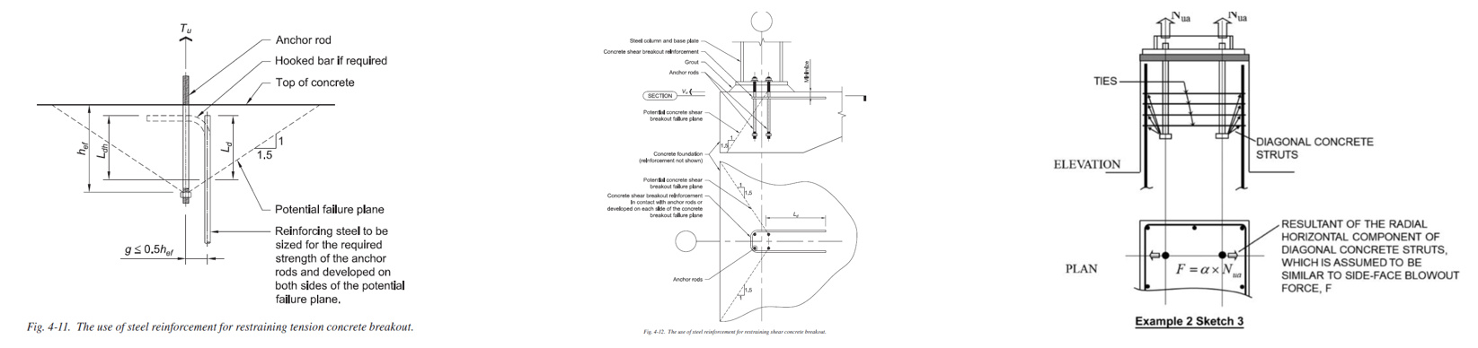
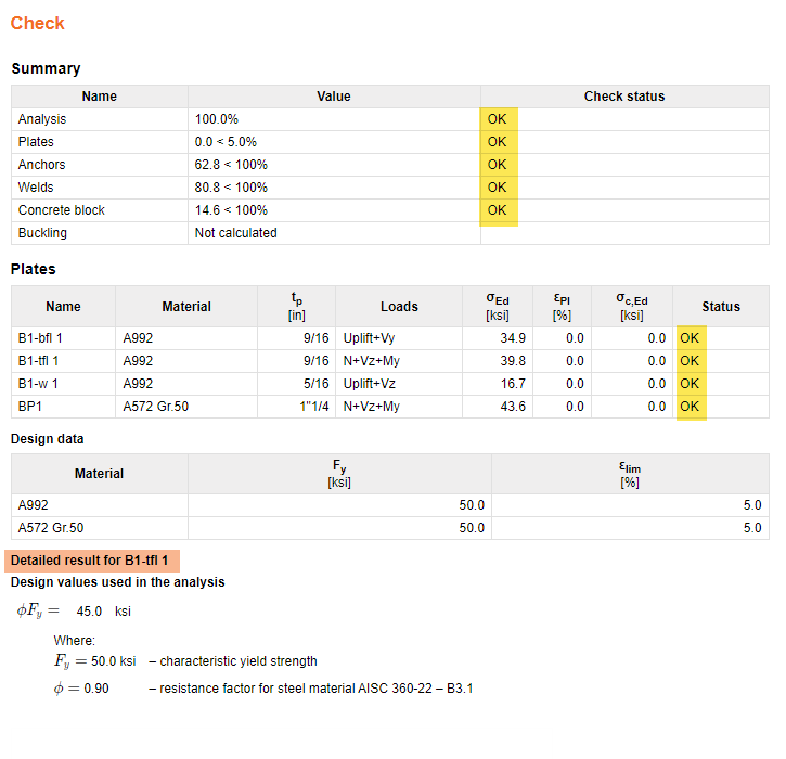
- Supplementary reinforcement: This is provided to restrain the breakout cones and is not specifically designed to resist any loads.
The design of the anchor and supplementary reinforcement is explained in the following literature:
- ACI-318 Commentary section R17.5.2.1 – This section provides recommended detailing practices for anchor reinforcement
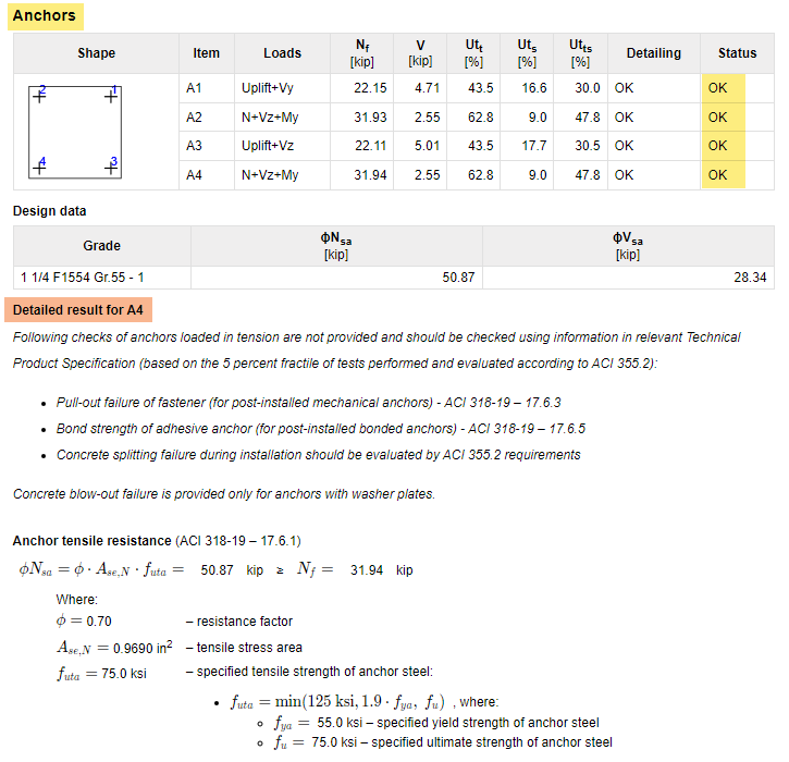
- Anchorage design for petrochemical facilities, ASCE, 2013 – This book provides potential strut and tie models that can be used to design breakout and side-face blowout limit states
- Design of anchor reinforcement in concrete pedestals, Widianto, Chandu Patel, and Jerry Owen, 2010—This paper presents a method for designing anchor reinforcement using the strut and tie model and explains a proposed design procedure.
For years, this has been a common pain for EoRs and structural designers. Designing the reinforcement in the concrete below the base plate is often time-consuming, especially when anchor forces exceed breakout capacity. IDEA StatiCa just unlocked a new complete workflow that enables engineers to model, analyze, and verify anchor reinforcement quickly and accurately.
Complete workflow explanation
IDEA StatiCa is a steel connection software very well known for its abilities when it comes to the base plate design. With the Connection application, you can model any base plate and design its anchors. However, if you find some of the conditions mentioned above, the anchors will fail by concrete breakout resistance.
The new workflow allows you to design the anchor reinforcement needed to transfer the forces into the concrete foundation.
Let’s review the proposed workflow:
1. Model and design the base plate in the Connection application
Start the base plate design in IDEA StatiCa Connection. Use the base plate operation to model steel plates, concrete blocks, anchors, and welds. The user can also use other operations to add stiffeners or gusset plates if the base plate has a bracing member. There are no geometric limitations.

Another option for users is to import the loads from other applications. Many of our integrations allow for the automatic import of critical information, such as loads and geometry, which reduces the duplication of modeling.
Once the import is made, the analysis is performed for multiple load combinations instead of resorting to envelope reactions.

2. Steel components design
IDEA StatiCa Connection code-checks all the model components: Steel members, base plate, bolts, and welds.
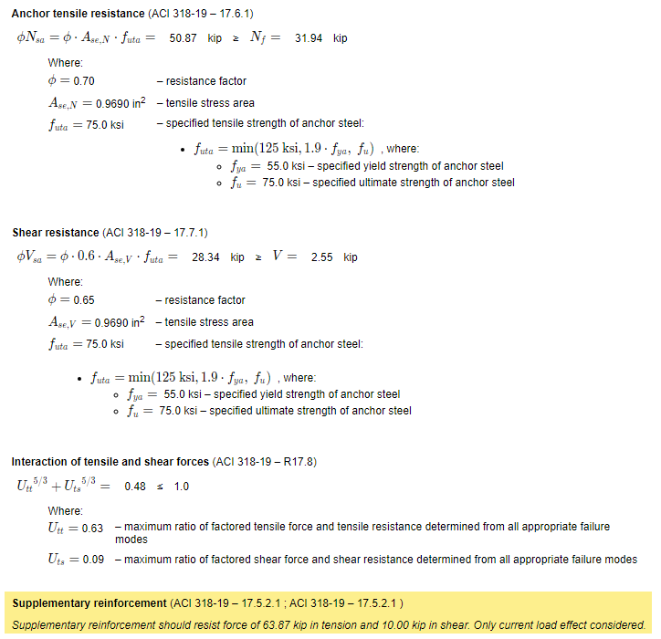
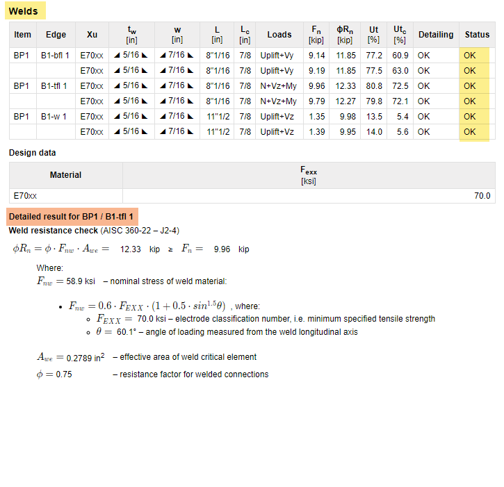
Click the link below to see the full detailed report:
3. Anchor bolts design
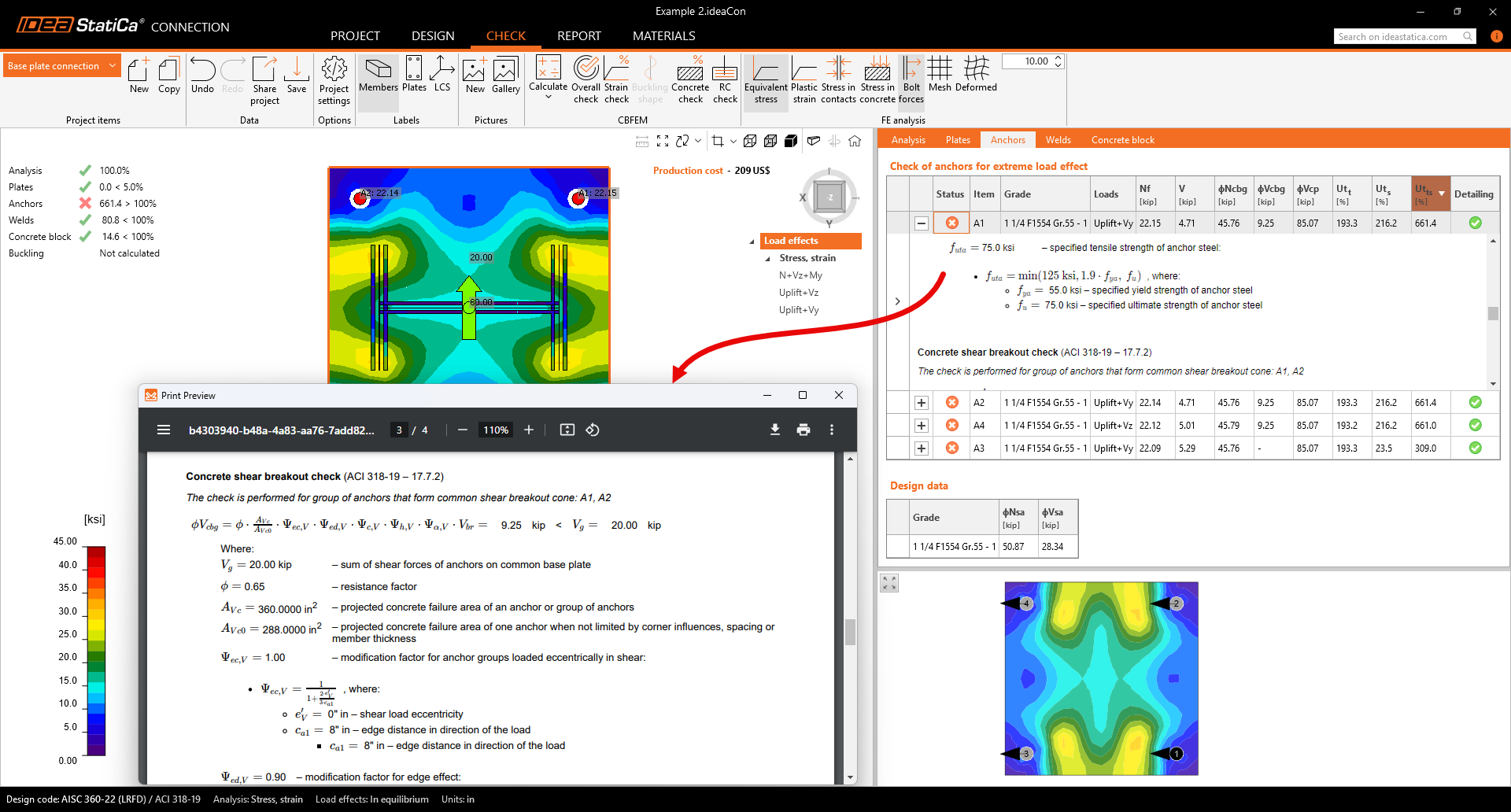
IDEA StatiCa Connection uses ACI-318 (2014 or 2019) formulas from Chapter 17 to design the anchor bolts. The code results are presented in a table, and you can look at the status of each anchor's checks. The verification also considers concrete breakout strength.
However, the check only considers unreinforced concrete.
You can now remove the concrete breakout checks from the results and instead receive the anchor forces needed to design the supplementary reinforcement.
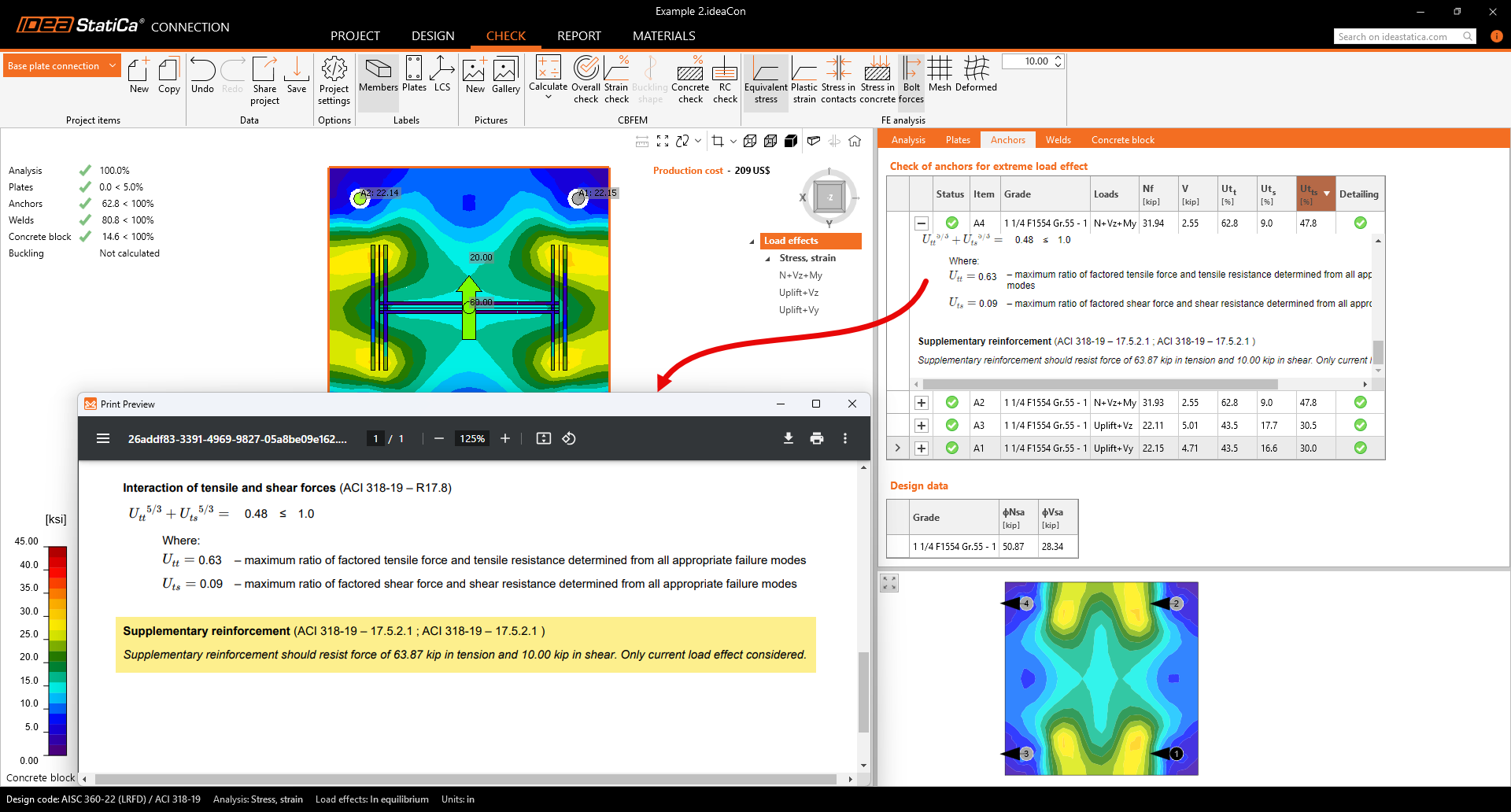
See the next steps for designing the concrete reinforcement in IDEA StatiCa.
4. Export the base plate model to the IDEA StatiCa Detail application
With IDEA StatiCa version 25, you can export the base plate model to the Detail application, and the model will be imported, including the base plate, anchors, concrete block, forces on the anchors and base plate, and load cases.
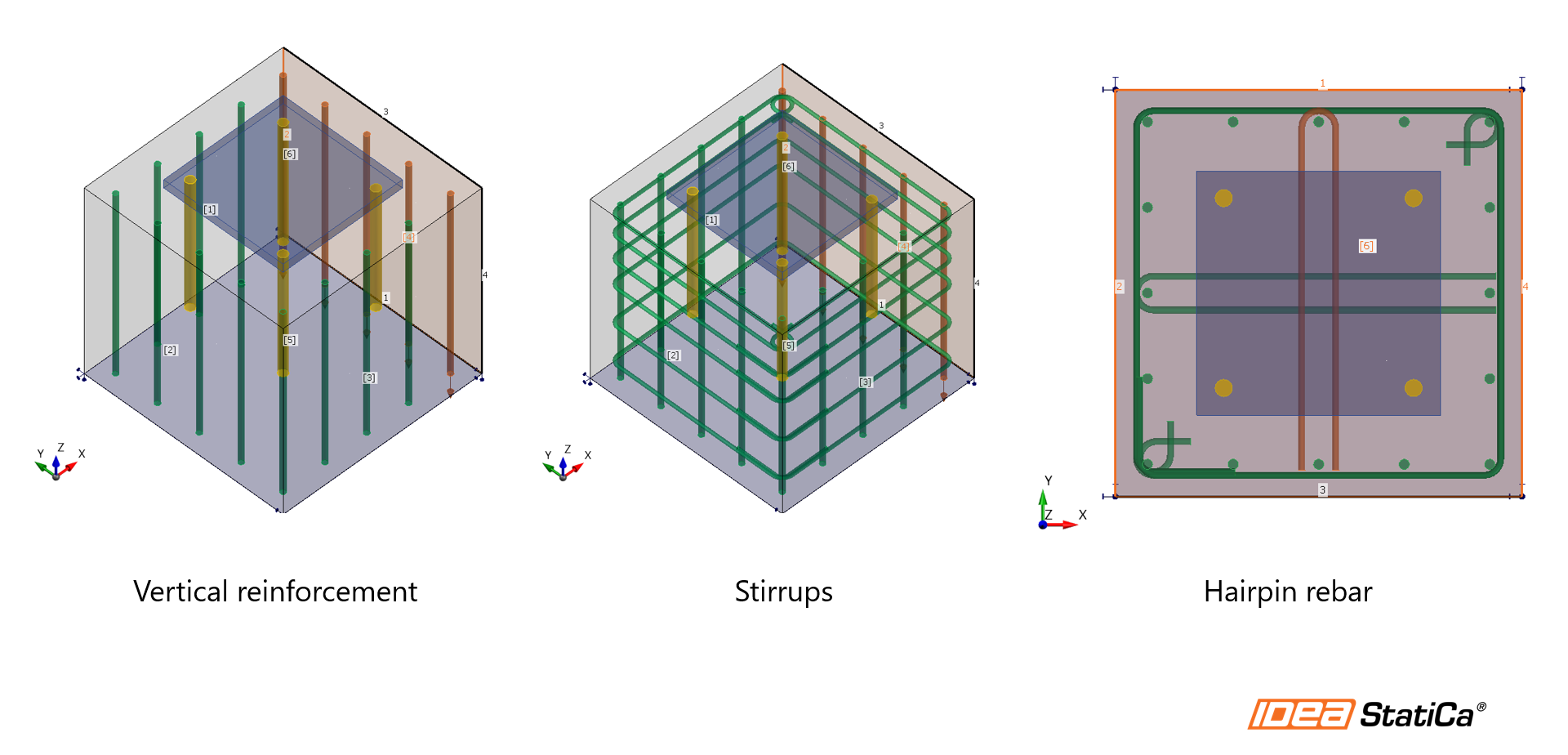
5. Model the reinforcement on the concrete block using operations
Before running the analysis, the user models the steel reinforcement in the imported model. Use the new rebar icon to add the reinforcement. Select from different options to input the steel rebars, such as the number of layers and bars in each layer. Visualize it using the 3D transparent view.
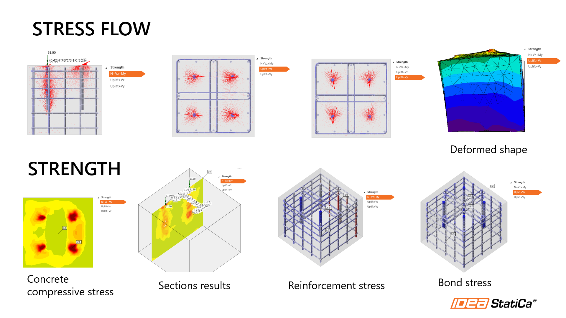
6. Run the analysis and Review the results
Once the analysis is finished, go to the Check tab and review the material utilization ratio and stresses. The stress flow in the Summary results shows the vectors of compression principal stresses in concrete and the utilization of the reinforcement to give you a basic overview. The user can review the concrete and steel strength, steel bond stresses, and deformations for the different load combinations.
Conclusion
IDEA StatiCa is helping thousands of engineers by developing software for structural engineering details.
The complete base plate design workflow simplifies complex tasks, reducing time spent on calculations of both parts, the steel base plate and the reinforced concrete foundation. With clear 3D visualization, users can better understand load paths and optimize the concrete reinforcement design.
Get a product demo
Related content
IDEA StatiCa Detail – Structural design of concrete discontinuities