Bolted flange plate moment connection – LRFD
A beam with cross-section W12\(\times\)40 is connected to a column with cross-section W10\(\times\)45. The joint is designed as a moment connection and is realized as bolted flange plate moment connection. All steel is grade A36 (fy = 36 ksi, fu = 58 ksi) and bolts are grade A307 (fy = 50 ksi, fu = 65 ksi). Fin plates at the beam flanges are with the thickness of 5/8'' and the fin plates at the beam web are with the thickness of 3/8''. The column is stiffened at the location of fin plates at the beam flanges and are with the thickness of 5/8''. The column is loaded by compressive force 200 kip, the beam by bending moment 800 kip-in and shear force 30 kip.
Geometry
Investigated connection
Cross-sections of column (left) and beam (right)
Geometry of fin plates
Manual assessment
Manual assessment is provided according to AISC 360-16. For simplification, the bending moment is considered to be transferred only by the flanges and the shear force only by the web. The shear force is assumed to be acting at the face of the column. The following checks are required:
- Bolt strength in shear – J3.6
- Bearing and hole tearout strength at bolt holes – J3.10
- Block shear strength – J4.3
- Tensile strength of connected elements – J4.1
- Shear strength of connected elements – J4.2
- Weld strength – J2.4
The design of beam and column is assumed to be checked elsewhere.
Distribution of forces
The bending moment is transferred via bolts on the beam flange. The distance between shear planes is 11.929''. The force acting on the group of bolts at flanges is 67.06 kip.
The bending moment is further transferred via welds connecting fin plates to the column flange. The distance between centers of gravity of welds is increased by the thickness of the fin plate, i.e. 11.929 + 5/8 = 12.554''. The welds are loaded by force 63.72 kip.
The bolts at the web are loaded by the shear force 30 kip and by a small shear force resulting from the bending moment caused by the eccentricity of assumed shear force acting at the column face, 1.75''. This shear force is neglected here because the utilization of bolts at the beam web is not expected to be very high and there is enough reserve.
The welds at the fin plate connecting the beam web are loaded by shear force 30 kip.
Bolt check
Bolts at the beam flange:
The shear force 67.06 kip is assumed to be evenly distributed between 8 bolts 3/4'' A307.
Shear strength:
\[\phi R_n = \phi F_{nv} A_b = 0.75 \cdot 27 \cdot 0.442 = 8.938 \,\textrm{kip}\]
Bearing strength:
\[\phi R_n = \phi 2.4 d t F_u = 0.75 \cdot 2.4 \cdot 0.75 \cdot 0.516 \cdot 58 = 40.394 \,\textrm{kip}\]
Hole tearout strength:
\[\phi R_n = \phi 1.2 l_c t F_u = 0.75 \cdot 1.2 \cdot (1.4-0.406) \cdot 0.516 \cdot 58 = 26.77 \,\textrm{kip}\]
The shear resistance of one bolt is 8.938 kip, i.e. the resistance of a group of 8 bolts is 67.184 kip. The resistance is sufficient to transfer shear force 67.06 kip.
Block shear strength:
\[\phi R_n =\phi (0.6 F_u A_{nv} + U_{bs} F_u A_{nt}) \le \phi (0.6 F_y A_{gv} + U_{bs} F_u A_{nt})\]
\[\phi R_n = 0.75 \cdot (0.6 \cdot 58 \cdot 2.97 + 1 \cdot 58 \cdot 0.82) \le 0.75 \cdot (0.6 \cdot 36 \cdot 4.44 + 1 \cdot 58 \cdot 0.82) = 143 \, \textrm{kip}\]
This example shows the block shear strength of the upper flange of the beam. The expected rupture is presumed to span across 4 bolts next to the beam web. Thus, it must resist half the load acting on the bolt group, i.e. 30.03 kip. The reserve is very high.
Tensile yielding of the fin plate:
\[\phi R_n =\phi F_y A_g = 0.9 \cdot 36 \cdot 5.00 = 162 \, \textrm{kip}\]
Tensile rupture of the fin plate:
\[\phi R_n =\phi F_u A_n = 0.75 \cdot 58 \cdot 3.98 = 173 \, \textrm{kip}\]
The plate is utilized at 41 %.
Bolts at the beam web:
The shear force 30 kip is assumed to be evenly distributed between 4 bolts 3/4'' A307.
Shear strength:
\[\phi R_n = \phi F_{nv} A_b = 0.75 \cdot 27 \cdot 0.442 = 8.938 \,\textrm{kip}\]
Bearing strength:
\[\phi R_n = \phi 2.4 d t F_u = 0.75 \cdot 2.4 \cdot 0.75 \cdot 0.295 \cdot 58 = 23.1 \,\textrm{kip}\]
Hole tearout strength:
\[\phi R_n = \phi 1.2 l_c t F_u = 0.75 \cdot 1.2 \cdot (1.365-0,406) \cdot 0.375 \cdot 58 = 17.81 \,\textrm{kip}\]
The shear resistance of one bolt is 8.938 kip, i.e. the resistance of a group of 4 bolts is 39 kip. The resistance is sufficient to transfer shear force 30 kip.
Shear yielding of the fin plate:
\[\phi R_n = \phi 0.6 F_y A_{gv} = 1 \cdot 0.6 \cdot 36 \cdot 3.72 = 80 \,\textrm{kip}\]
Shear rupture of the fin plate:
\[\phi R_n = \phi 0.6 F_u A_{nv} = 0.75 \cdot 0.6 \cdot 58 \cdot 2.50 = 65 \,\textrm{kip}\]
The shear strength of the fin plate, i.e. 65 kip is sufficient to transfer the shear load 30 kip.
Weld check
Welds near the beam flange:
Welds connecting the fin plate at the beam flanges to the column flange are required to transfer 63.72 kip. Welds are loaded at an angle \(90^\circ\). Weld electrode E70XX is used and its size is 3/8''.
\[F_{nw} = 0.6 F_{EXX} (1+0.5 \sin^{1.5} \theta) = 0.6 \cdot 70 \cdot (1+0.5 \sin^{1.5} 90^\circ) = 63 \,\textrm{ksi}\]
\[\phi R_n = \phi F_{nw} A_{we} = 0.75 \cdot 63 \cdot 4.213 = 199 \,\textrm{kip}\]
The weld strength is sufficient.
Welds near the beam web:
Welds connecting the fin plate at the beam web to the column flange are required to transfer 30 kip. Welds are loaded at an angle \(0^\circ\). Weld electrode E70XX is used and its size is 5/16''.
\[F_{nw} = 0.6 F_{EXX} (1+0.5 \sin^{1.5} \theta) = 0.6 \cdot 70 \cdot (1+0.5 \sin^{1.5} 0^\circ) = 42 \,\textrm{ksi}\]
\[\phi R_n = \phi F_{nw} A_{we} = 0.75 \cdot 42 \cdot 4.374 = 138 \,\textrm{kip}\]
The weld strength is sufficient.
Check in IDEA StatiCa
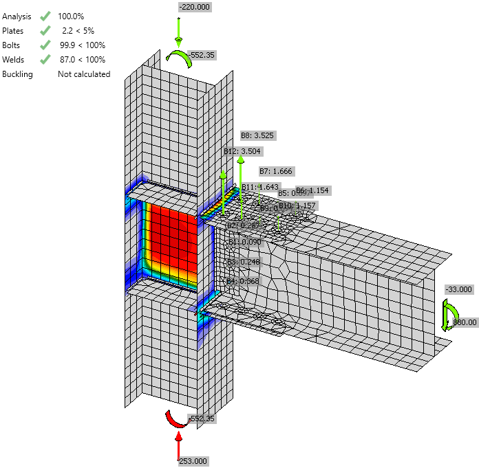
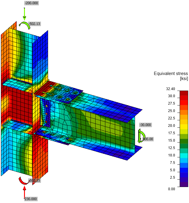
The plates are checked by finite element analysis. The bilinear material model is used with the yield strength multiplied by steel resistance factor \(\phi = 0.9\). The forces acting on other components of the connection, i.e. bolts and welds, are also determined by finite element analysis but their resistance is checked using standard formulas from AISC 360-16. The most stressed weld element is checked and with further loading, the stress in the weld is spreading into further weld elements. Therefore, the ultimate weld resistance is higher than simply dividing the force by weld utilization.
Von Mises stress
Plastic strain including the tensile forces in bolts
Check of stress and strain of plates
Check of bolts
Check of welds
Comparison
It is clear that the finite element analysis shows the different distribution of internal forces than simple assumptions. Shear force is also partially transferred via fin plates at the beam flanges as can be seen from the tensile forces in bolts and high stresses caused by bending of the fin plate near the column flange. The individual strengths of bolts and welds show perfect match but the loads and load directions are different.
While the manual check is showing that the joint is fully utilized due to shear strength of bolts at beam flanges, IDEA still shows some reserve. The loads can be increased by 10 % to achieve full utilization in IDEA. This can be expected due to the simplification in load distribution in manual assessment.
The check in design software IDEA StatiCa Connection is in close agreement with the manual assessment according to AISC 360.
Téléchargements joints
- AISC.pdf (PDF, 1,2 MB)


