Deflection check according to EN 1992-1-1
Description of benchmark
Reference calculation
Calculation of deflection performed using the IDEA StatiCa BEAM application is compared to reference calculation presented in: Example 6.2, Calculation of deflection, T-beam.
References:
Procházka et al. Training Design of concrete structures according to ČSN EN 1992, Part 1, Reinforced concrete, structural fire design, provisions for concrete bridges, ČBS a ČBS Servis, 2009, p. 105-110.
Geometry of beam
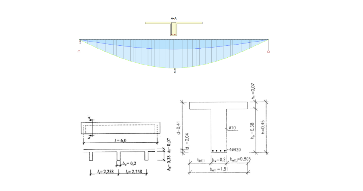
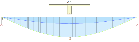
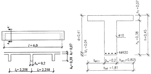
Cast in place beam of T-shaped cross-section presented in figure below. Simply supported beam of 6.0 m span is assumed for structural model. Geometry of cross-section and position and type of reinforcement is presented in figure on the right side.
Characteristic values of loads: Dead load: Σgkj = 8.2 kN/m, Long-term live load: qk = 23.5 kN/m.
Reference calculation - main calculation values and results
Quasi-permanent combination:
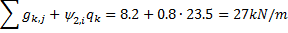
Mid-span bending moment for quasi-permanent combination:
Concrete strength class: C20/25
Cement class: N, Creep coefficient φ( ∞,to)
φ( ∞,to = 28) = 3.2
fck = 20MPa, fcd = 13.3MPa, fctm = 2.2MPa, Ecm = 30GPa
Reinforcing steel:
10505(R), B500B: fyk = 500MPa, fyd = 435MPa
Cross-sectional characteristics for long-term load actions
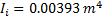
Uncracked cross-section
Cracking bending moment:
Flexural compliance:
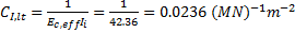
Cracked cross-section
Flexural compliance:

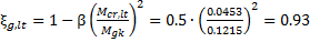
Distribution coefficient:
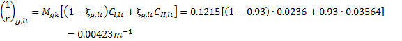
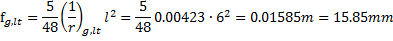
Curvature:
Deflection:
Deflection calculation using IDEA StatiCa BEAM
For detailed comparison of calculation results can be used project file, which is attached to this benchmark. The results presented below correspond to Extreme “4” for Section in the middle of beam span. Values presented in reference calculation (previous chapter) are marked by red rectangles.


Calculated deflection value in red rectangle in table below represents the long-term deflection caused by long-term loads including effect of creep (Quasi-permanent combination).
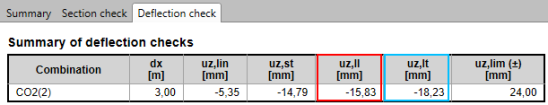
Deflection value in blue rectangle represents total deflection including effect of creep (Characteristic combination).