ETABS BIM link for steel connection design (AISC)
As a pre-requisite for this link Microsoft .Net 6 is required. This can be downloaded here. This should also be installed with administrator rights.
Comment activer le lien
- Téléchargez et installez la dernière version de IDEA StatiCa
- Vérifiez que vous utilisez une version autorisée de votre solution MEF/BIM
IDEA StatiCa intègre les liens BIM dans vos solutions MEF/BIM lors de l'installation. Vous pouvez voir le statut et activer autres liens BIM pour des logiciels installés aussi plus tard dans l'outil d'installation des liens BIM.
Veuillez noter qu'il faut des étapes supplémentaires pour activer des liens BIM de quelques solutions MEF avec IDEA StatiCa.
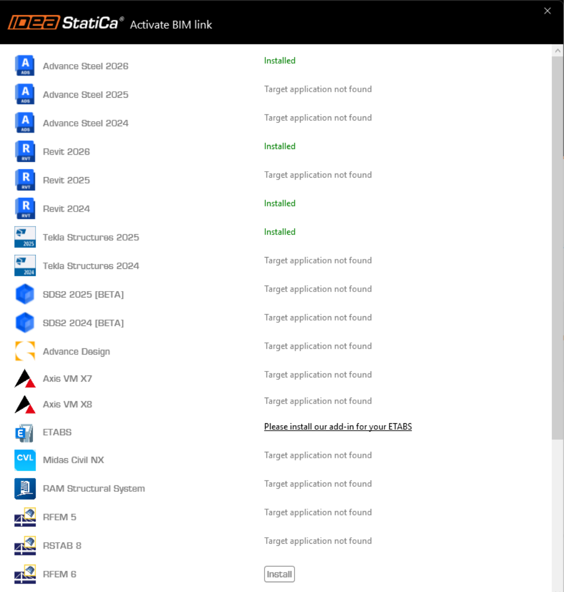
Ouvrez IDEA StatiCa et allez à l'onglet BIM et ouvrez l'outil d'installation des liens BIM (Activation du lien BIM...).
Une notification avec le texte « Voulez-vous autoriser cette application à apporter des modifications à votre appareil ? » peut apparaître. Dans ce cas, veuillez confirmer avec le bouton Oui.
Le lien BIM pour le logiciel sélectionné (si trouvé) sera installé. L'écran vous montrera aussi le statut d'autres liens BIM qui peuvent être déjà installés.
There are some additional manual steps required in ETABS to finish the integration procedure:
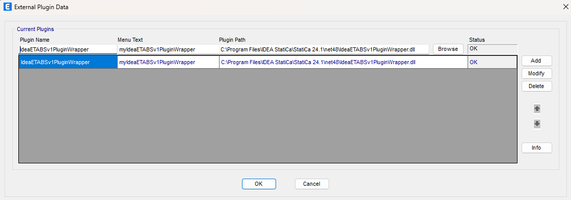
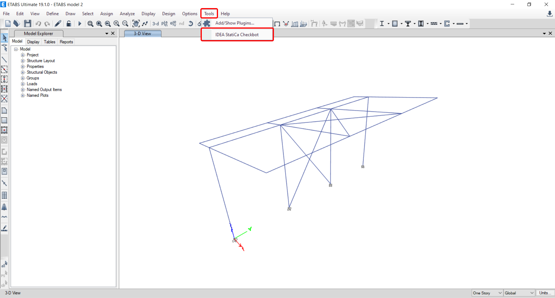
Start ETABS and Click Tools > Add/Show Plugins to open the Plugin Manager dialog. This option lets you install and add add-ins (programs) to the appropriate places in the ETABS menu.
Browse for
C:\Program Files\IDEA StatiCa\StatiCa 24.1\net48\IdeaETABSv1PluginWrapper.dll
(for older versions of IDEA Statica C:\Program Files\IDEA StatiCa\StatiCa 23.0\IdeaETABSv1PluginWrapper.dll
or C:\Program Files\IDEA StatiCa\StatiCa 22.1\ETABSv18PlugIn_IDEAStatiCa.dll).
You can edit the plugin's name displayed in your dropdown menu as IDEA StatiCa Checkbot, then click Add.
Remark
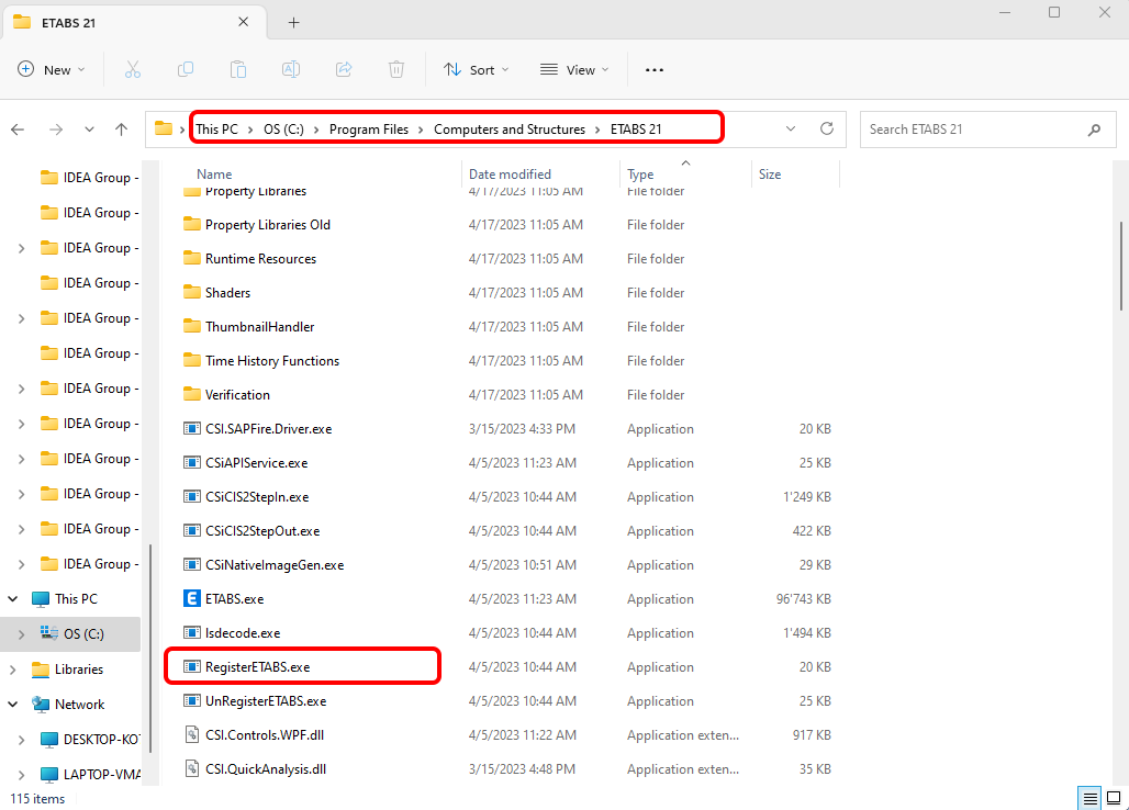
In case the window with the IDEA StatiCa Checkbot doesn't appear, please go to C:\Program Files\Computers and Structures\ETABS 22 and run as Administrator the file RegisterETABS.exe.
How to use the link
Open the attached AISC project in ETABS and run the calculation.
The BIM link should be automatically integrated. You can find it in the top ribbon under Tools -> IDEA StatiCa Checkbot. This will open the Checkbot application.
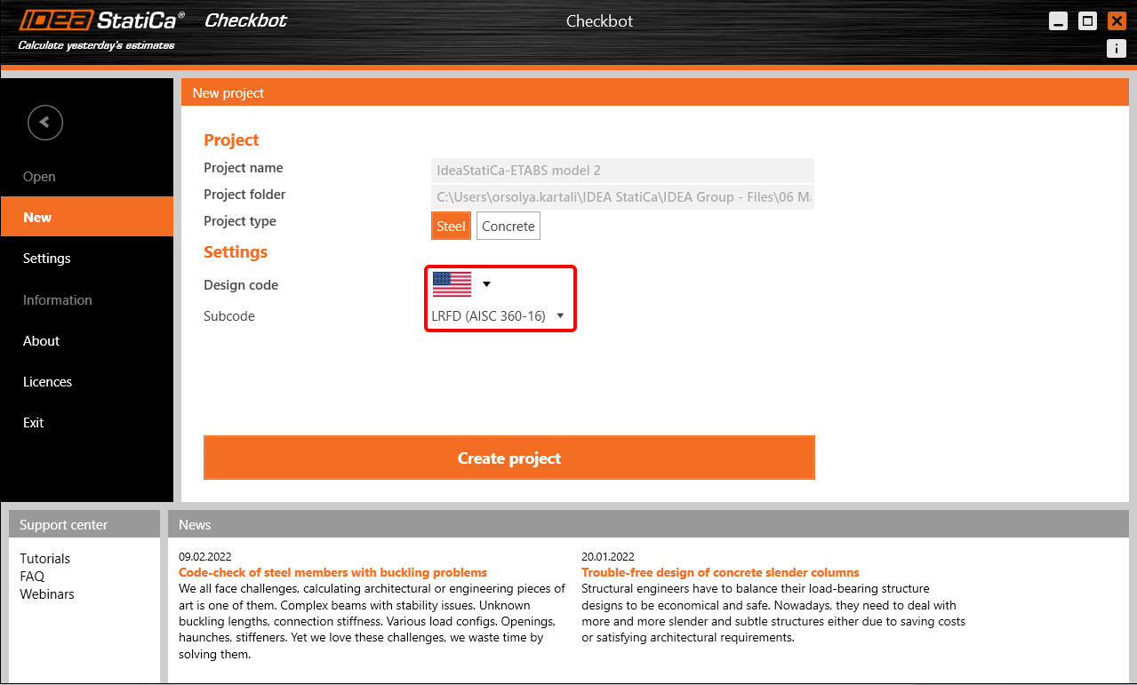
Select the New option with project type Steel, AISC design code and sub-code LRFD (AISC 360-16). Then select Create project.
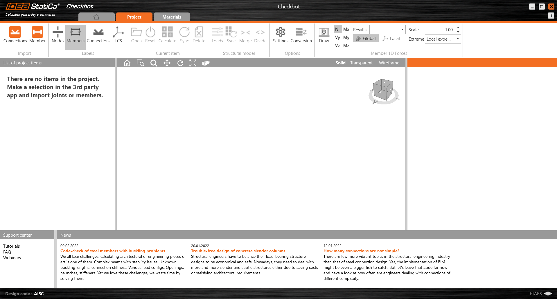
The new Checkbot project is ready to import connections from ETABS.
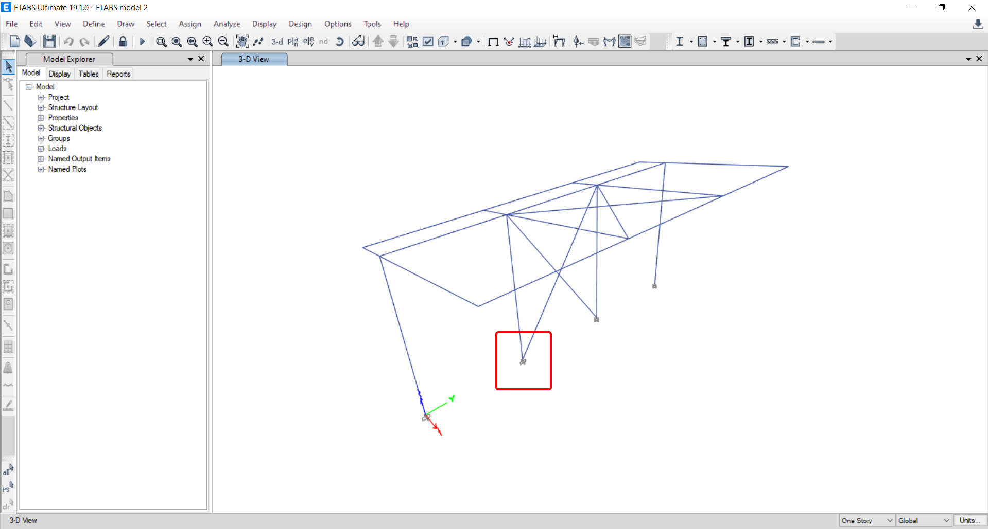
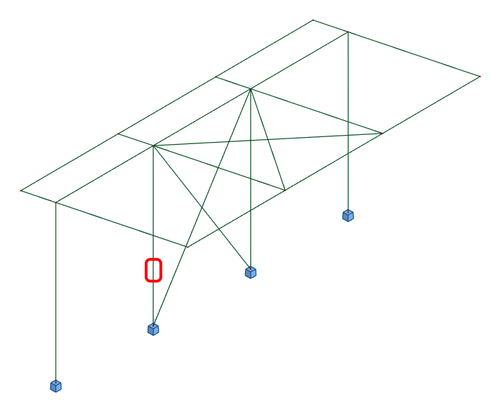
In ETABS, select one of the inside columns making sure you also select the lowest node.
Import
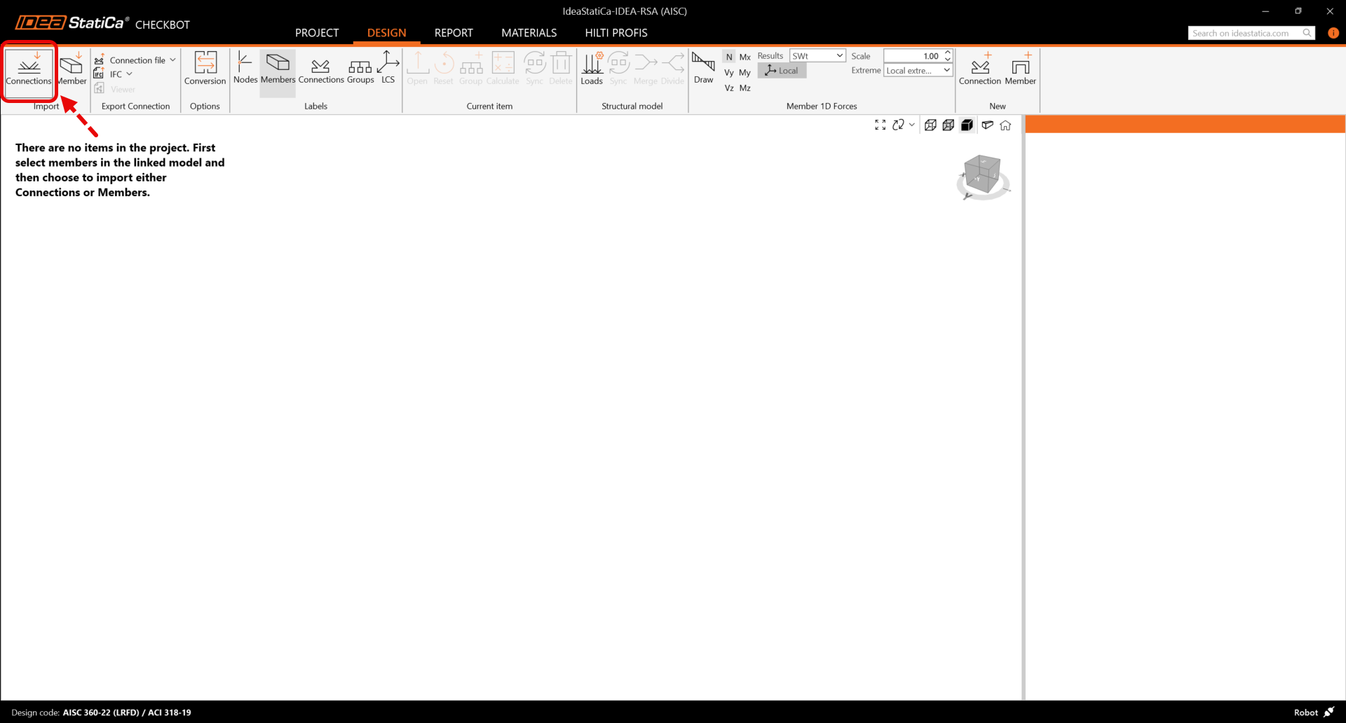
Then in Checkbot select Connections.
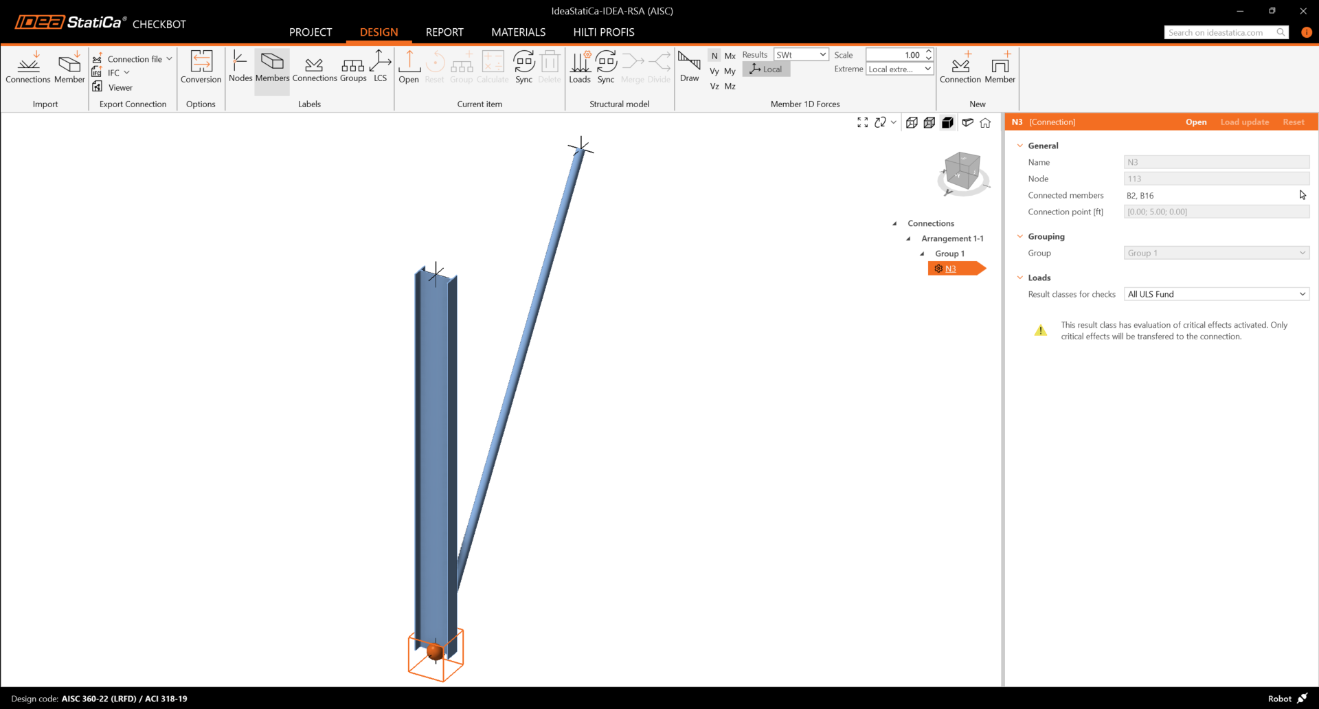
This will import the column and its load effects into Checkbot - with the same coordinates, orientations, and section sizes as per the FEA model.
Please note that your node and member numbering might be different.
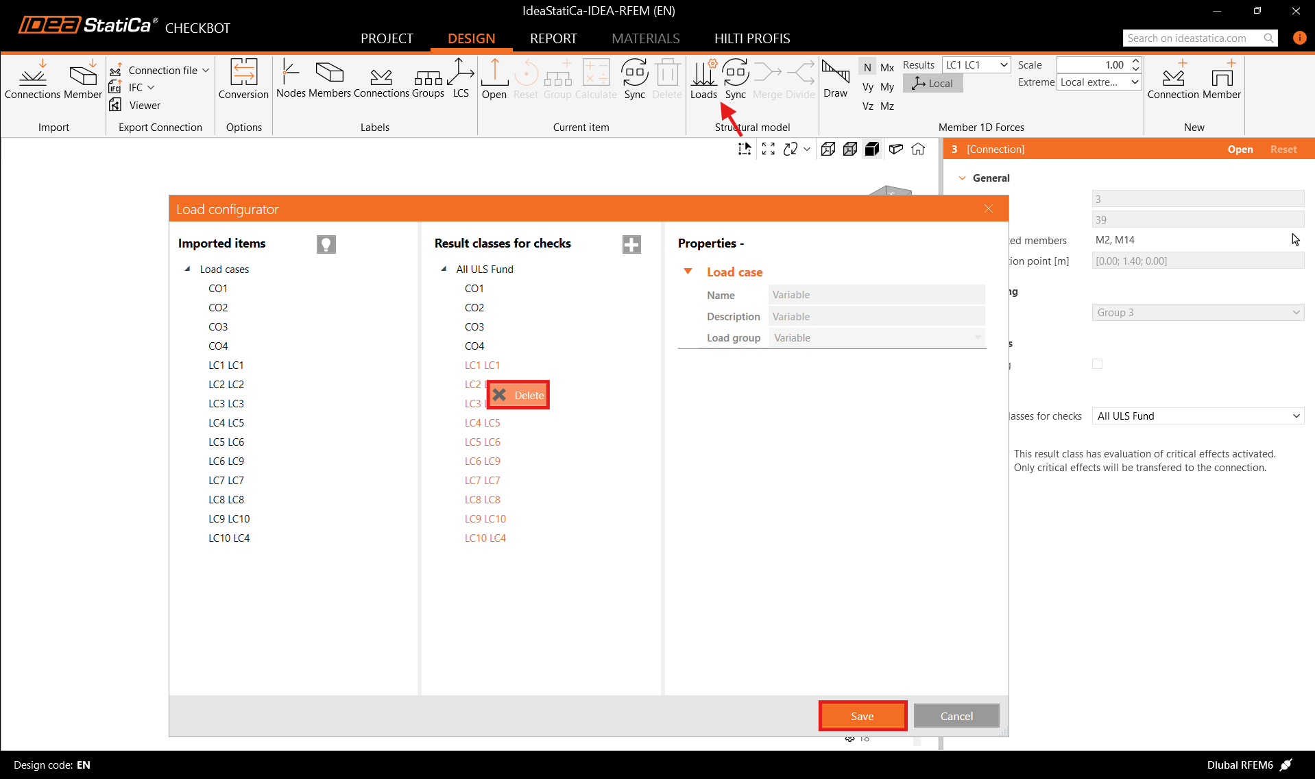
Before running the analysis, make sure to review the Result classes for checks and adjust the load cases accordingly. In the Load configurator dialog, you can see all imported load cases and load combinations on the left and the result classes used for checks in the middle. If some load cases are not relevant for your design verification, exclude them by right-clicking on the selected loads and removing them from the result classes list.
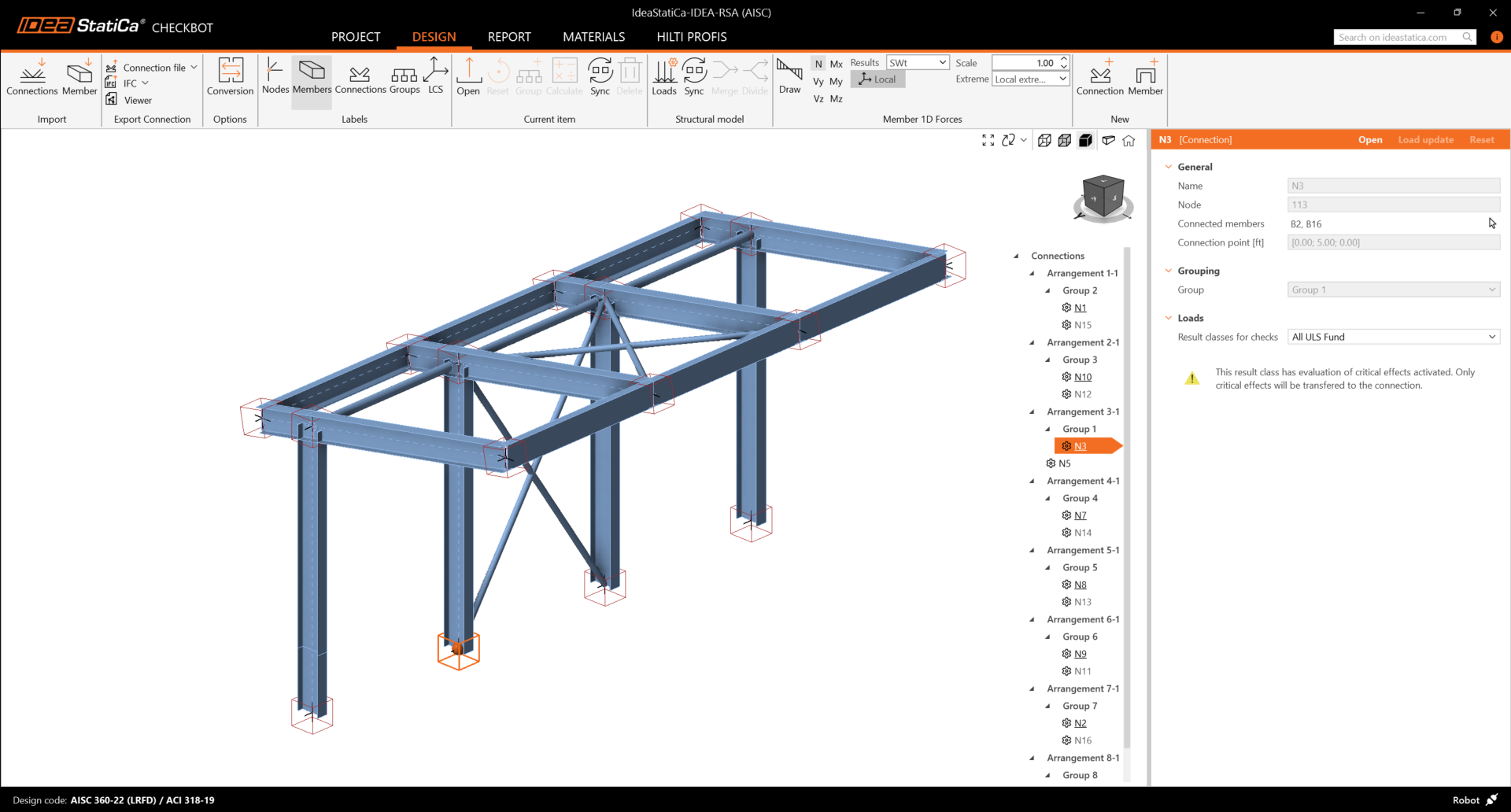
Please note the 3D workspace is designed to show an overview of the imported structure and not a detailed view of the actual connections. For more information on Checkbot, see here.
For several FEA solutions, you can also import multiple connections into Checkbot in the same manner as above. Instead of selecting one node and the connected members, you can select multiple nodes and members and import them all at once.
Geometry
In the list of project items under Connections and with a connection highlighted in Checkbot you can either right-mouse click and select Open or click the ribbon command Open to start designing, code-checking, and reporting.
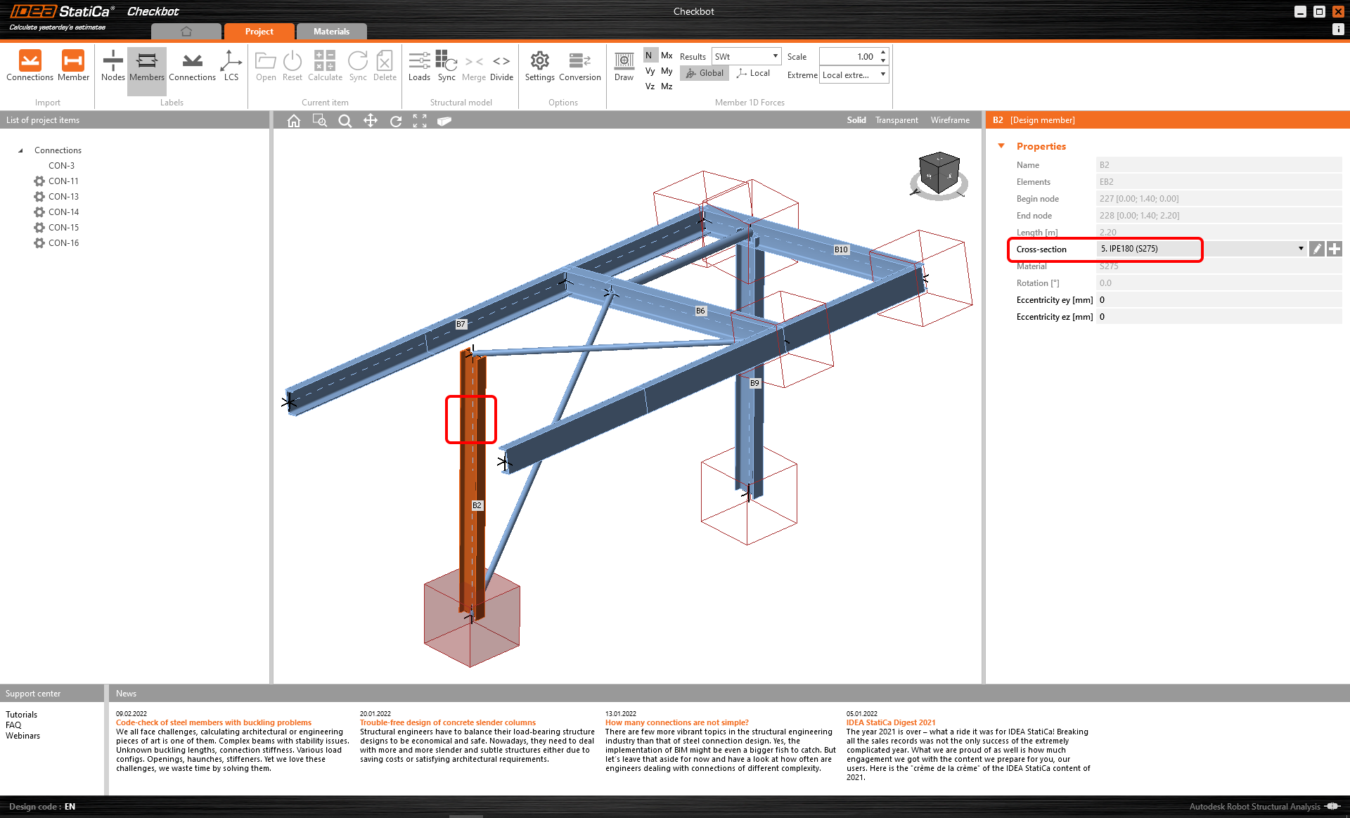
The settings of members are taken from the original FEA application. You can, however, change the section size of any member on the main Checkbot screen, but this will break the link with the FEA application in this session unless it's synchronized again.
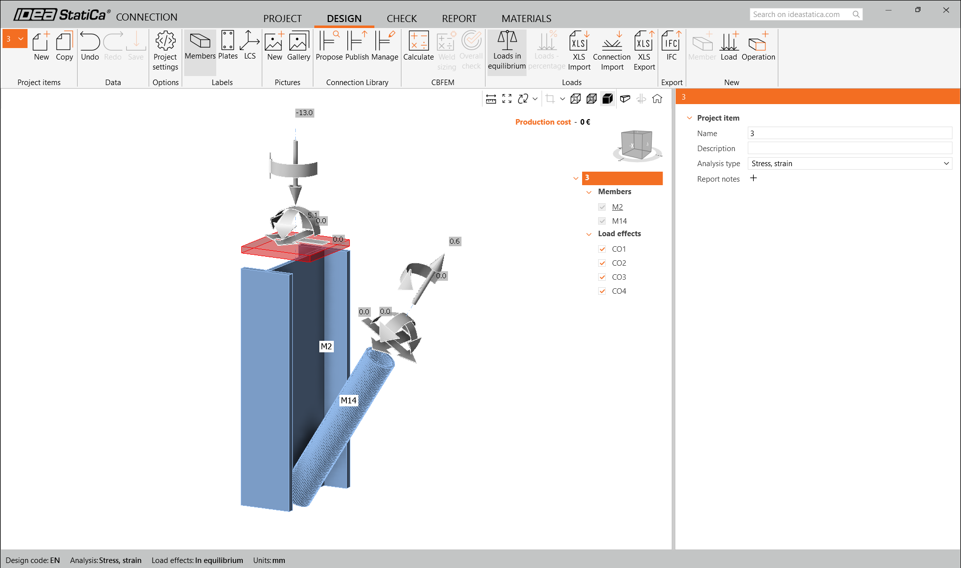
The imported connection is opened in the IDEA StatiCa Connection application.
You may see none or different Load effects from your FEA solution, depending on how the load case combinations have been defined. By default, IDEA StatiCa will choose the most critical for code-checking purposes. (* Some BIM solutions are not able to store the load case combination results)
For more information on Load effects, see here.
Design
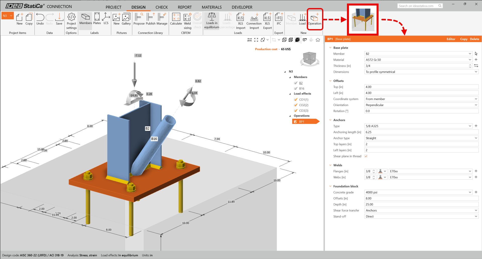
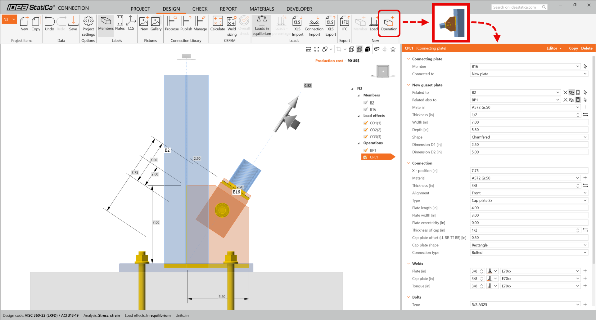
To create the base plate connection, we are going to use the manufacturing operations. On the upper ribbon select Operation, choose the Base plate and Connecting plate operations, and adjust the parameters as shown below:
Base plate
Connecting plate
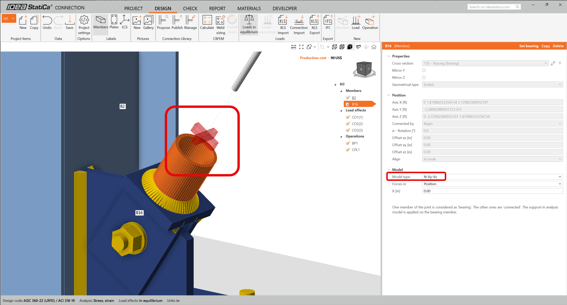
As we have connected the diagonal brace using a single bolt connection, we must also change the Model type of the brace member to N-Vy-Vz. Select the brace in the list of Members and modify the Model type in the drop-down list.
This is what the designed connection looks like.
Code check and Report
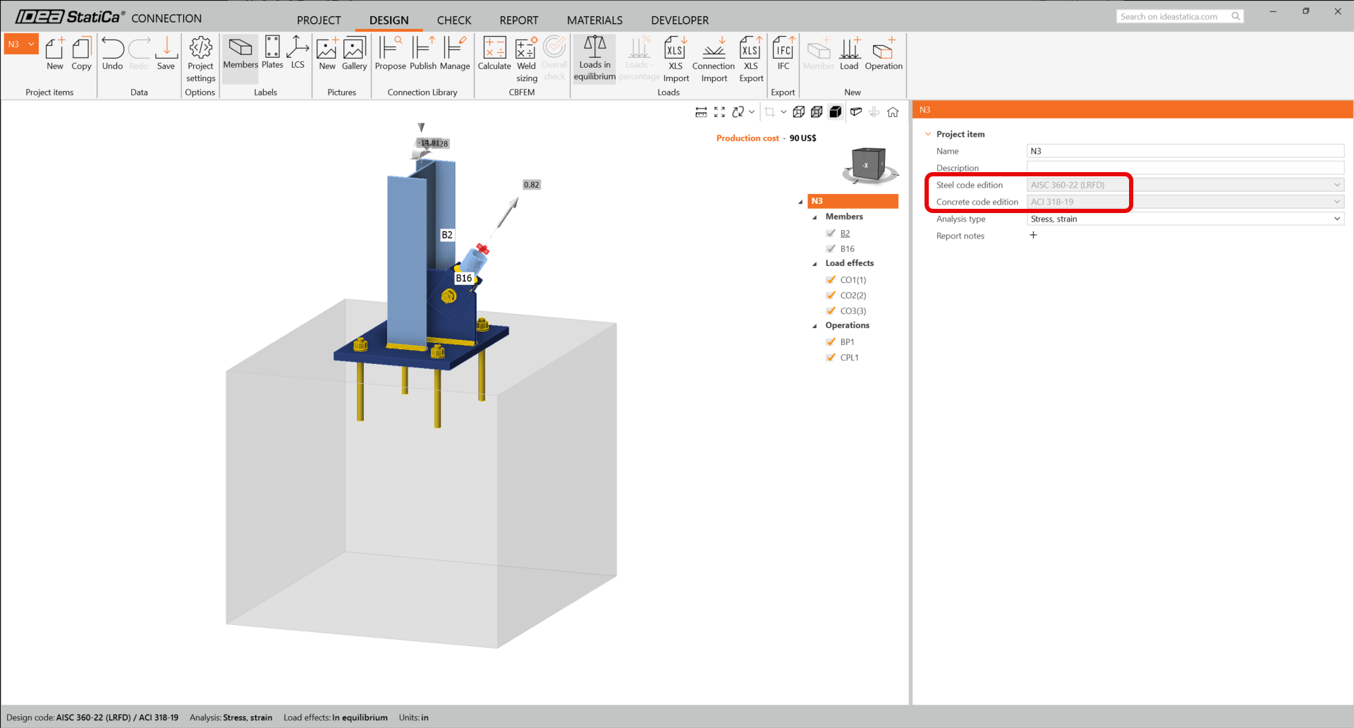
To run a code check, we must also make sure that the code is correct in IDEA StatiCa Connection. From the Design tab in the Connection label N3, ensure that LRFD 2022 is being used.
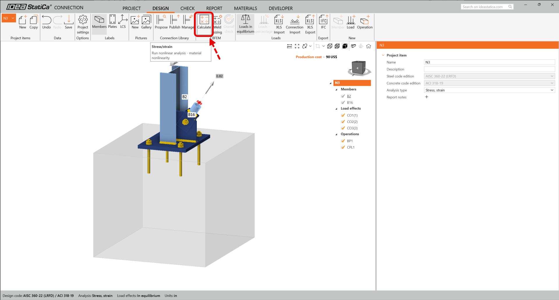
Now run a code check using the Calculate icon in the CBFEM panel from the top ribbon.
Within IDEA StatiCa Connection you can carry out many different types of analysis and code-checks. For more information please see here.
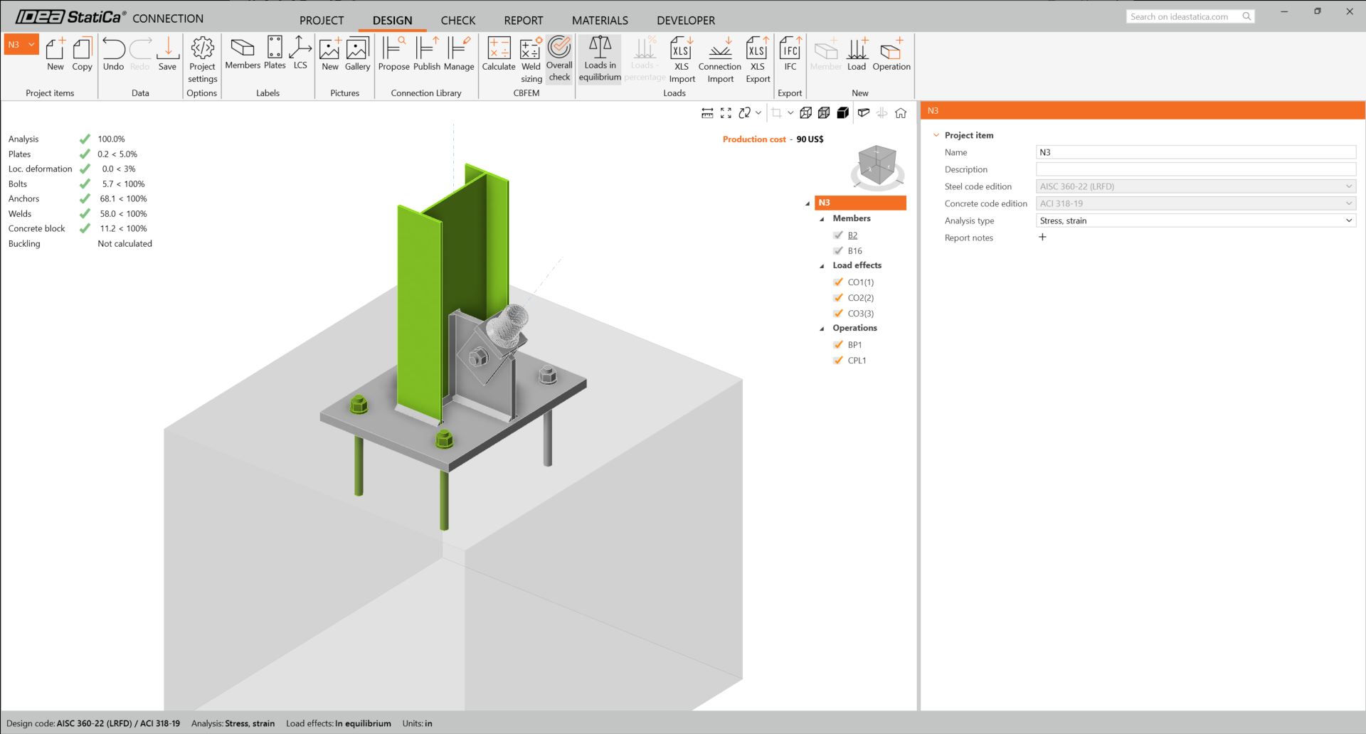
You will get the results of the nonlinear analysis.
The detailed results for plates, bolts, welds, anchors can be displayed using the ribbon menu. In the image below the Deformed shape with Equivalent stress is being displayed.
You can go through the results on anchors as well.
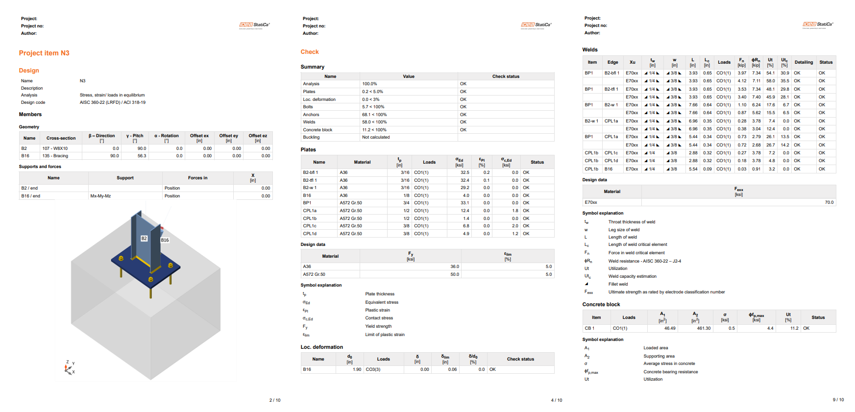
Once the code-check is finished, you can create the report containing results and diagrams for your connection model in the Report tab.
IDEA StatiCa offers a fully customizable report to print out or save in an editable format. For more information, please see here.
Save and exit this connection back to Checkbot.
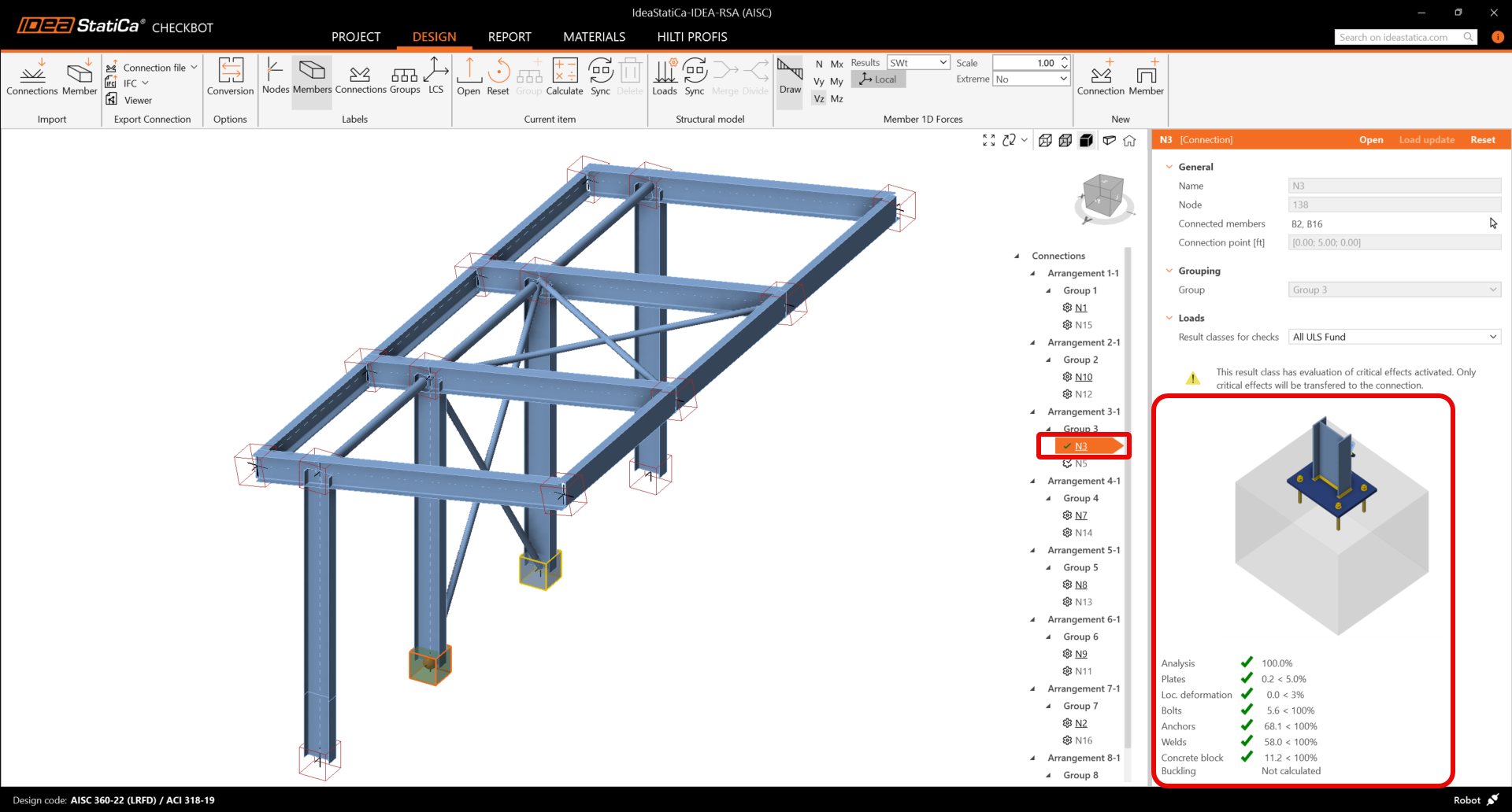
In Checkbot, you will see a green tick next to the connection. This means that the connection is valid and has passed all code-checks. In the Connection panel, you can also see a representation of the connection and a summary of the code-check results.
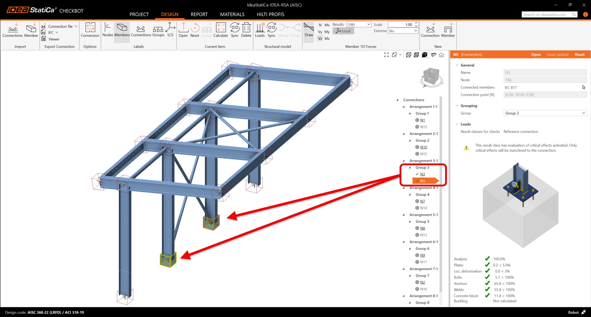
If multiple similar connections are present in Checkbot, they will be automatically grouped together. Users then have the option to batch designed the grouped connections.
In the example below, you can see that both baseplate connections, under group 3, have passed their respective code-checks while the remaining connections are yet to be validated.
Synchronisation du modèle
De temps en temps, il y a des modifications de votre modèle MEF/BIM, par exemple une taille différente de section d'un élément ou des charges différentes. Il est possible de les synchroniser entre Checkbot et le modèle MEF/BIM.
Il y a deux alternatives :
- Synchroniser l'Élément actuel (si un ou plusieurs assemblages sont sélectionnés)
- Synchroniser le Modèle structural importé entier
Pour vérifier cette fonction, vous pouvez changer la taille ou forme de section d'un élément dans votre application BIM/MEF ou modifier un cas ou combinaison de charge, etc. : changez les poteaux pour une section plus petite. N'oubliez pas de réanalyser le modèle MEF.
Dans Checkbot, sélectionnez les attaches conçues (il peut y avoir plus qu'une) et puis Synchronisation au panneau Élément actuel.
Le projet dans Checkbot sera actualisé, la conception d'attache sera enregistrée mais les résultats ne seront plus valides. Vous pouvez voir que le poteau est actualisé – avec le même changement qu'au modèle MEF.
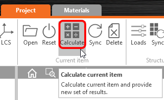
Il faut seulement vérifier les attaches en surbrillance encore une fois en sélectionnant Calculer au panneau Élément actuel. Veuillez noter que des changements plus significatifs du modèle peuvent exiger des étapes de validation supplémentaires pour les attaches affectées (comme ci-dessus).
Si les attaches ne donnent pas de résultats désirés, vous pouvez les rouvrir pour optimiser la conception (renforcer-les si elles échouent la vérification ou alléger si l'utilisation est trop basse).
You have successfully linked ETABS with IDEA StatiCa Connection via Checkbot.


