Loads in IDEA StatiCa Detail - Advanced Topics
From frequent customer inquiries and our own experience, we have put together the following topics:
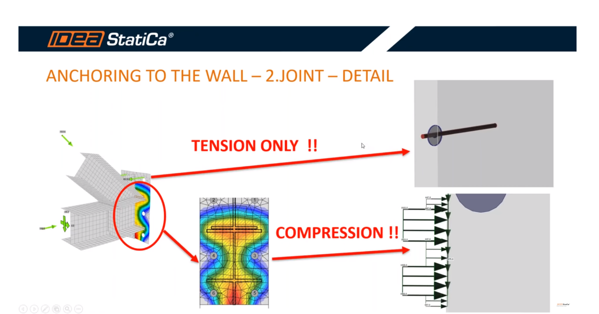
- How to input compressive load under the anchoring plate to the model
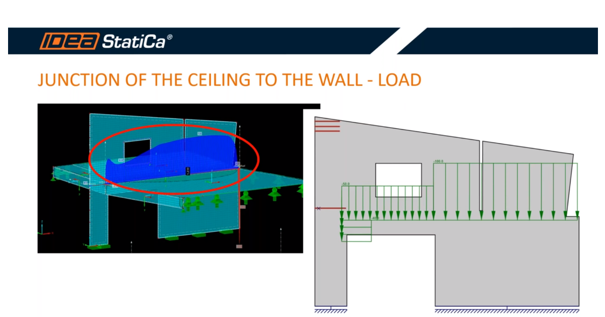
- How to input the load from the ceiling
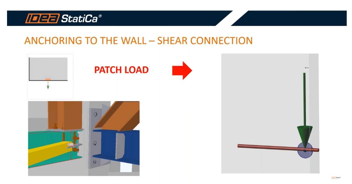
- How to input the load from the shear connection
- How to input the partial factors for ULS and SLS
Each issue is briefly described and then explained as part of an already streamed webinar.
Note: If you need a reminder of what types of load can be used in the application, continue to the article General Description of Load impulses in Detail application.
How to input compressive load under the anchoring plate to the model
The stress in the concrete receives from the analysis in the IDEA StatiCa Connection. Due to the possibility of displaying the effective areas, we are able to integrate the stress on each effective area and get the forces. Due to the fact that the stress is constant along with the height of the effective area, we use uniform load to simulate the effect of stress under the anchoring plate.
How to input the load from the ceiling
The monolithic junction of the ceiling to the wall induces load, which can not be neglected. According to the shape of the shear force in the place of the junction from the FEA, we can adjust the equivalent load to the model.
How to input the load from the shear connection
The shear connection is possible modeled using a special load device called "Patch load". This entity is capable of distributed point load over an effective radius (area) which is defined by the user.
The option when the force is transferred directly to the concrete or reinforcement bars is derived from the realization of the connection in the wall. We have used the option for direct transfer to the reinforcement bars due to the effect of welding the anchors to the wire fabrics. It is really important to realize that the shear joint transfers, apart from the vertical load, also bending moment out of the plane of the wall. This effect cannot be covered in the 2D model in IDEA StatiCa Detail.
How to input the partial factors for ULS and SLS
Load cases as self–weight or ceiling are added in the characteristic values. If we input the load cases from the joints, we apply the partial factor of 1 due to the design value extracted from the IDEA StatiCa Connection. Nevertheless, in SLS, the situation is not so simple due to the fact that design values cannot be separated from the point of view of permanent and variable loads and divided by appropriate partial factors. The reason is the non-linear analysis in IDEA StatiCa Connection, so we cannot use the superposition of the loads. Regarding this effect, we have chosen a partial factor of 0.75, which comes out from the equation 1/1.35.
Watch the part of our webinar dedicated to correct input of the partial factors for ULS and SLS.


