Load effects displayed in the scene
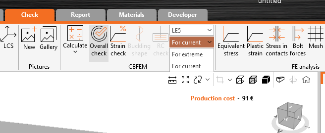
When more than one load effect is used, users can check what effect every single load effect in the structure has in the results. This can help users to understand the overall results that are presented.
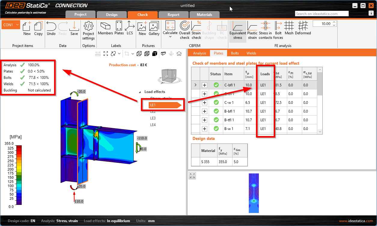
For easier orientation, all calculated load effects are shown directly in the tree in the scene under the Check tab, so users can quickly choose the load effect and check the results for the selected one.
The calculated load effects are available directly in the tree in the 3D scene. Disabled load effects in the Design tab are not shown in the Check tab tree.
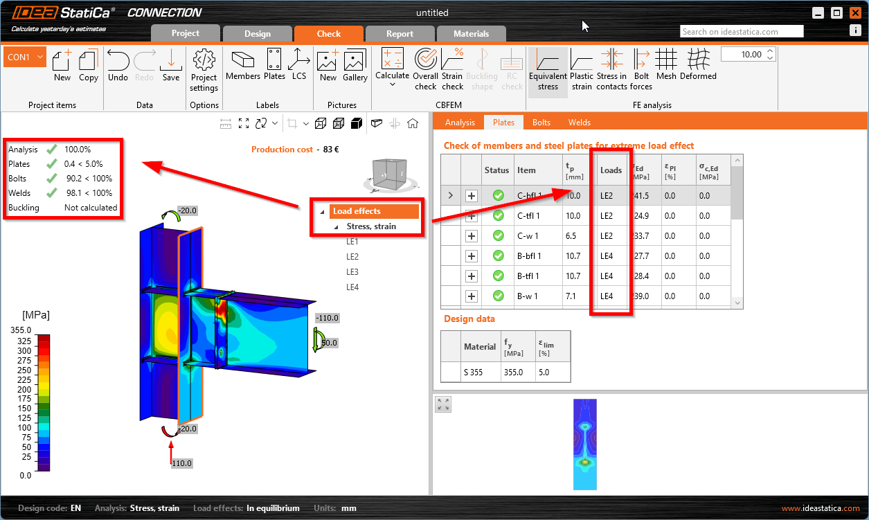
When the main Load effects header (or the Stress, strain item under) is selected, the results show a mix of all load effects, while for each connection part, there can be a different critical load effect. These results are shown:
- in brief results
- in the scene (stress maps)
- in the check tables
When a specific load effect is selected, results for this load only are shown everywhere – in the result overview, in the scene, and in tables.