
Parametric design in IDEA StatiCa Connection - Flush moment end plate connections
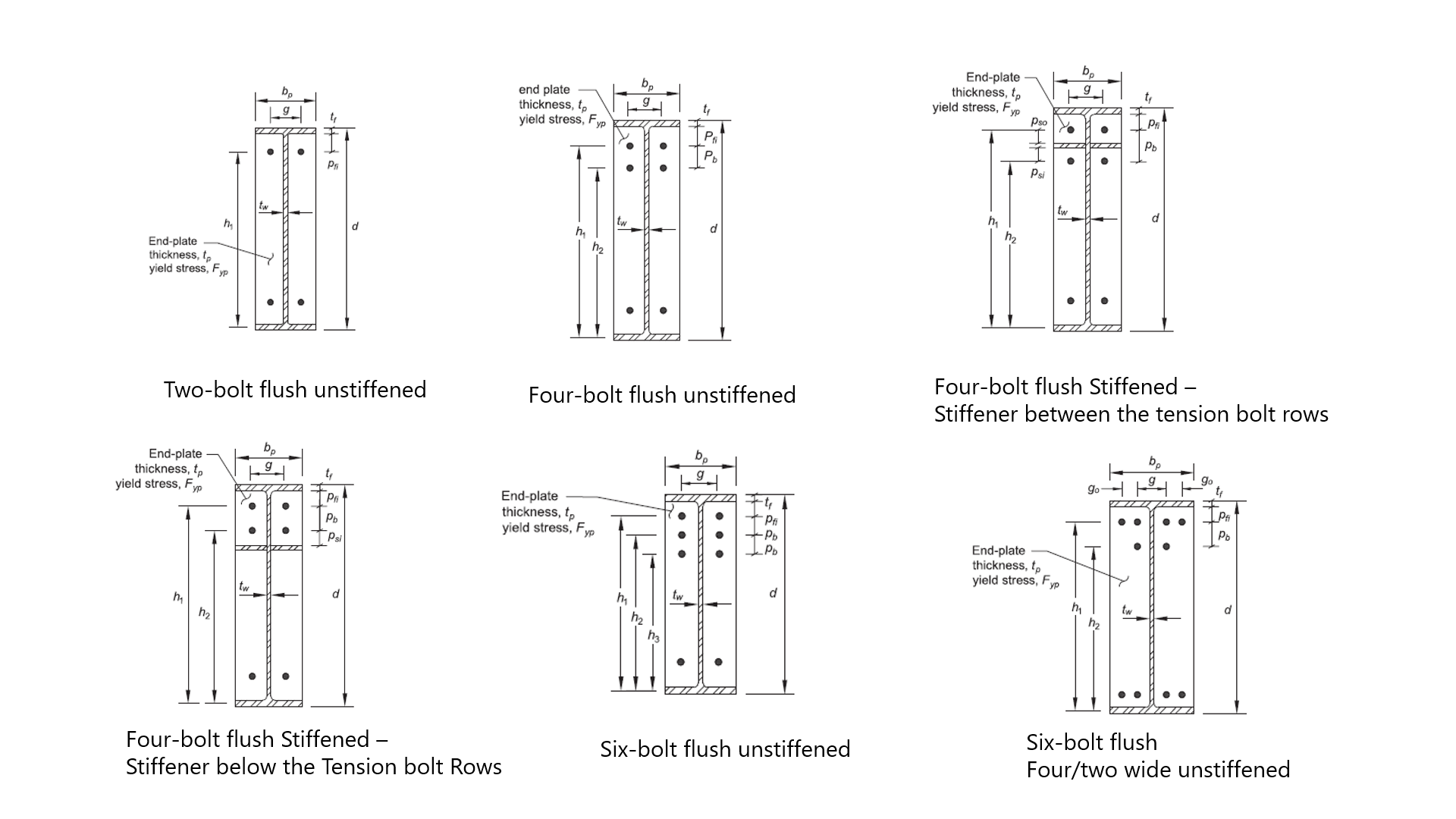
The configurations available are from the AISC Design Guide 39: End-Plate Moment Connections. The following picture summarizes the different flush configurations:
This tutorial is intended to be followed using imperial units. The finished template is at the end of this article.
1 Set up the environment
To use parameters in your daily job, you must first enable the Developer tab. Open a new connection file
Go to Preferences and check the Developer mode.
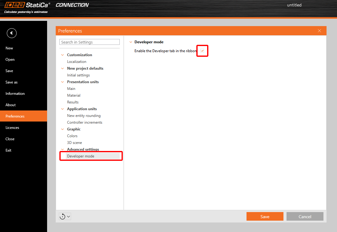
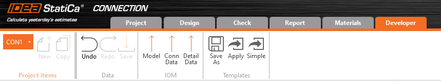
In the upper ribbon, a Developer tab appears.
2 Set up the base connection design
Now, open the following Connection file:
Since this template will include all the moment end plate flush configurations, we need to add all the operations possible for this template.
Review the operations:
- EP1 - Moment end plate
- STIFF1 - Stiffeners for the column member
- RIBMid2 - Stiffener for the end plate located between the tension bolts
- RIBEnd2 - Stiffener for the end plate located below the tension bolts
- GRD1 - Bolts operation for the end plate configuration containing four wide bolts
3 Set up the parameters
3.1 Obtain parameter values
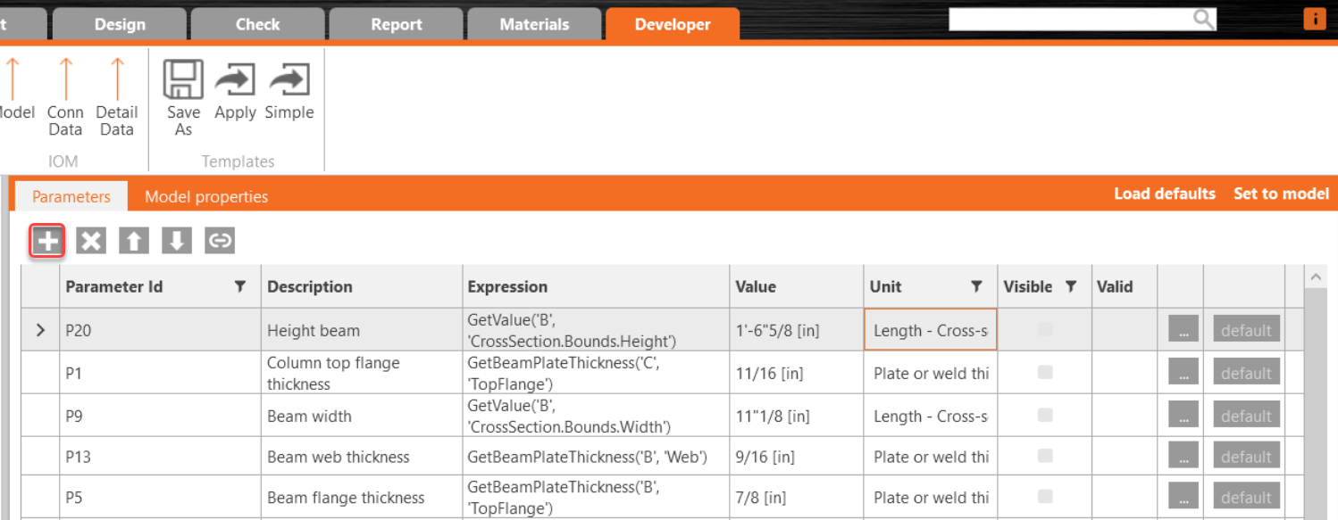
Go to the Developer tab, click the Plus button, and add the following parameters to get the values from the current model.
Notes:
- Use the same Parameter ID
- Copy and paste the expression from the table
- Use the dropdown menu for the Unit selection
| Parameter ID | Description | Expression | Unit |
| P20 | Beam height | GetValue('B', 'CrossSection.Bounds.Height') | Length - Cross section |
| P1 | Column top flange thickness | GetBeamPlateThickness('C', 'TopFlange') | Plate or weld thickness |
| P9 | Beam Width | GetValue('B', 'CrossSection.Bounds.Width') | Length - Cross section |
| P13 | Beam web thickness | GetBeamPlateThickness('B', 'Web') | Plate or weld thickness |
| P5 | Beam flange thickness | GetBeamPlateThickness('B', 'TopFlange') | Plate or weld thickness |
Parameter ID - Unique ID utilized within the software
Description - Arbitrary text
Expression - Text, Number, Function, Boolean, Value. For more, see the Reference Guide
Value - The value inputted in the Expression cell displayed in the unit system
Unit - Several possibilities (length, area, stress,...), SI Units necessary. However, later, the conversion unit expressions are used to input imperial units
Visible - When the box is checked, the parameter is visible under Design tab in the Operations section.
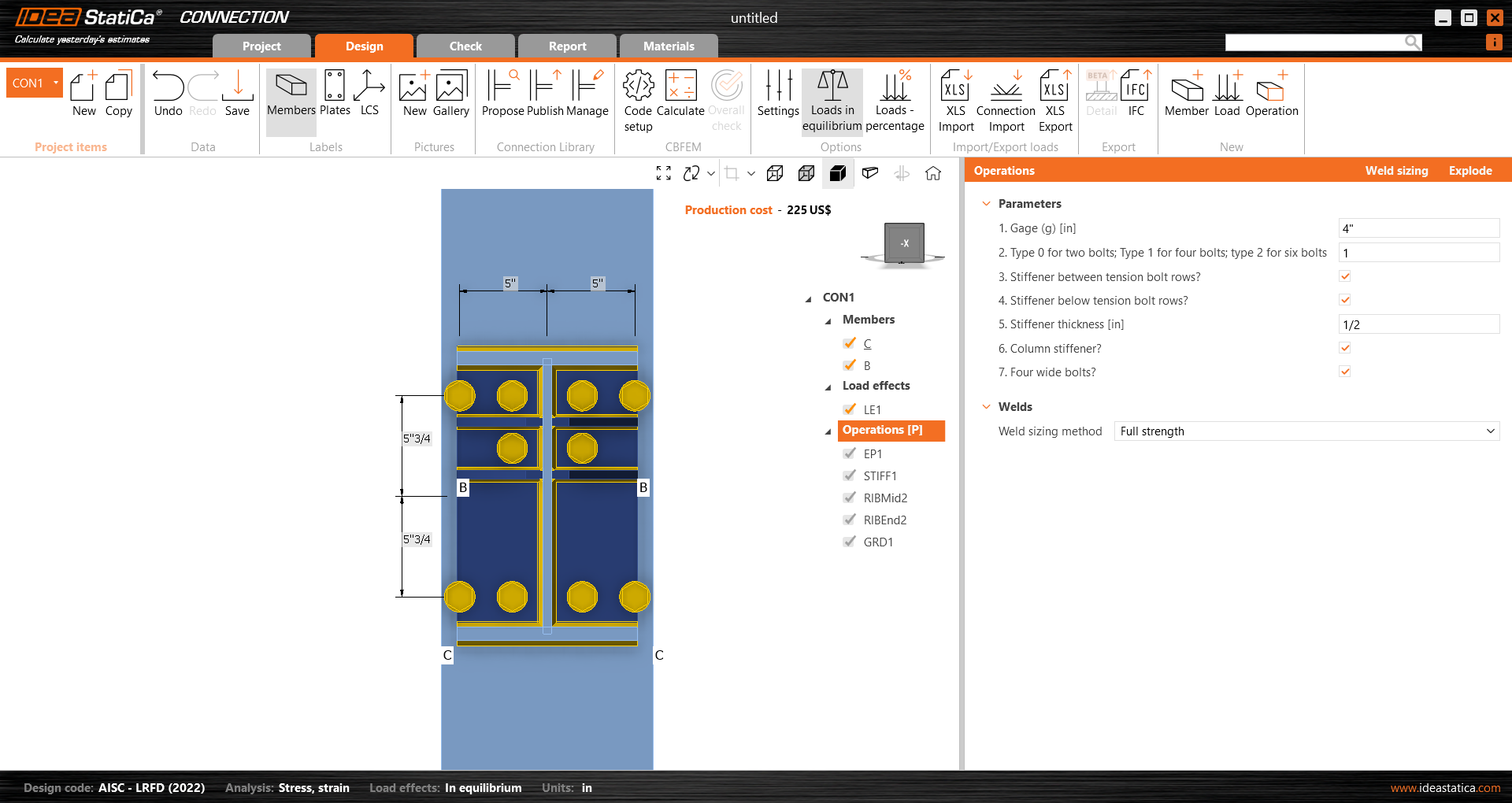
3.2 Visible parameters
Now, let's create the visible parameters; those are the ones we will use to request information from the user.
Notes:
- Use the same Parameter ID
- Copy and paste the expression from the table
- Use the dropdown menu for the Unit selection
- Numerical values can be requested, like in the following table parameters P4, D5 and P17.
- Boolean parameters can be set up by writing True in the value cell like P11, P12, P18 and P19. We will use them to learn what moment end plate configuration type is needed.
| Parameter | Description | Value | Unit | Visible |
| P4 | 1. Gage | 0.1016 | Plate or weld thickness | Yes |
| D5 | 2. Type 0 for two bolts; Type 1 for four bolts; Type 2 for six bolts | 1 | None | Yes |
| P11 | 3. Stiffener between tension bolt rows? | True | None | Yes |
| P12 | 4. Stiffener below tension bolt rows? | True | None | Yes |
| P17 | 5. Stiffener thickness | 0.0127 | Plate or weld thickness | Yes |
| P18 | 6. Column stiffener? | True | None | Yes |
| P19 | 7. Four wide bolts? | True | None | Yes |
Units
IDEA StatiCa Connection app always works in the metric system. When using imperial units, it converts all the values and presents them in imperial units in the interface. The input is also in the metric system when setting up parametric templates.
That is why the default values will be input in the value cell for P4=0.1016 meters and P17=0.0127 meters. In imperial units P4=4 inch, P17=0.5 inch.
3.3 Calculation Parameters
Now, let's add the parameters that will be used to calculate values for the operation inputs. Add the following parameters; after the table, see the explanation of each parameter.
Notes:
- Use the same Parameter ID
- Copy and paste the expression from the table
- Use the dropdown menu for the Unit selection
| Parameter id | Description | Expression | Unit |
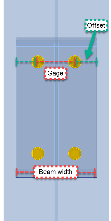
| D1 | Right/left offset for EP1 | -((P9-P4)/2) | Length-Cross section |
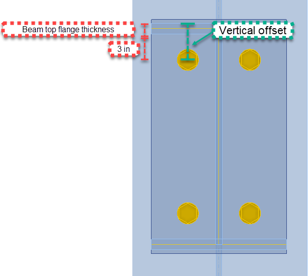
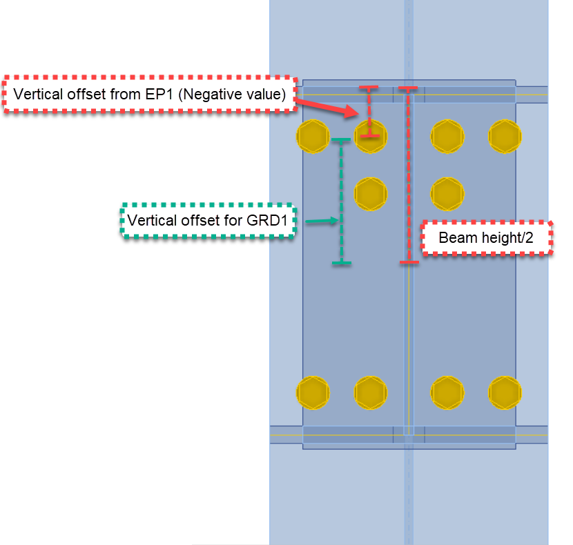
| D4 | Vertical offset | -(P5+Length(1.75,'in')) | Length - Cross section |
| P10 | Input for EP1 bolts layers | Concat(D4,' ','-','0.0762*',D5) | None |
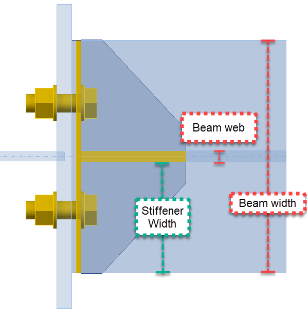
| P14 | Width Stiffener | P9/2-P13/2 | Length - Cross section |
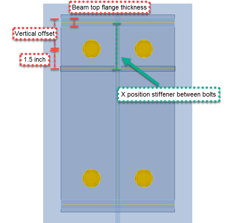
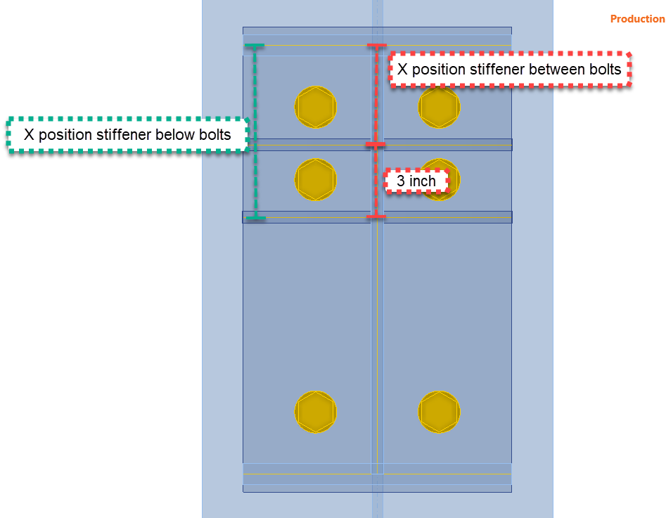
| P15 | X position Stiffener between bolts | (-D4)-(P5/2)+Length(1.5,'in') | Length - Cross section |
| P16 | X position stiffener below bolts | P15+Length(3,'in') | Length - Cross section |
| P21 | Vertical offset (Rows) GRD1 | (P20/2)+D4 | Length - Cross section |
| P22 | Input rows GRD1 | Concat('-',P21,';',P21) | None |
| P23 | Gage/2 | (P4/2)+Length(3,'in') | Length - Cross section |
| P24 | Input position GRD1 | Concat('-',P23,';',P23) | None - Cross section |
- D1= Right and left offset for the Endplate operation—This parameter helps us input the Right and left layers in the endplate operation. It is calculated using two previous inputs: beam width and the gage input, which will be a value provided by the user. See the table below with the used parameters.
- D1=-(Beam Width-gage)/2
- D4= Vertical offset—This parameter affects the end plate operation's top and bottom bolt layers. In this case, a fixed value of 3 inches will be used. As mentioned, the application works in the metric system, so if you use a fixed-length input, use a conversion function. You can find more functions here.
- D4=-(Beam top flange thickness + 3 inch)
- P10= This parameter will be the direct input for the Top layer in the End plate operation
- P14= Width stiffener: This parameter is the stiffener width input in the Rib operations.
- P14=(Beam width/2)-(Beam web thickness/2)
- P15=X position Stiffener between bolts - This parameter is used to locate the stiffener along the end plate. The position is taken from the center line of the top flange beam.
- P15=-(Vertical offset)-(Top flange thickness/2)+1.5 inches
- P16= X position stiffener below bolts - This parameter is for the position of the stiffener below the bolts, in case the user activates it.
- P16=X position stiffener between bolts + 3 inch
- P21= Vertical offset for GRD1 - This parameter will be used in case the wide bolts configuration is requested.
- P21= (Height of the beam/2)+ Top layer EP1 offset
- P22= Input rows GRD1 - Direct input for the grid operation 1
- P23= Parameter for the horizontal position of bolts for GRD1
- P23= (Gage/2) + 3 inch
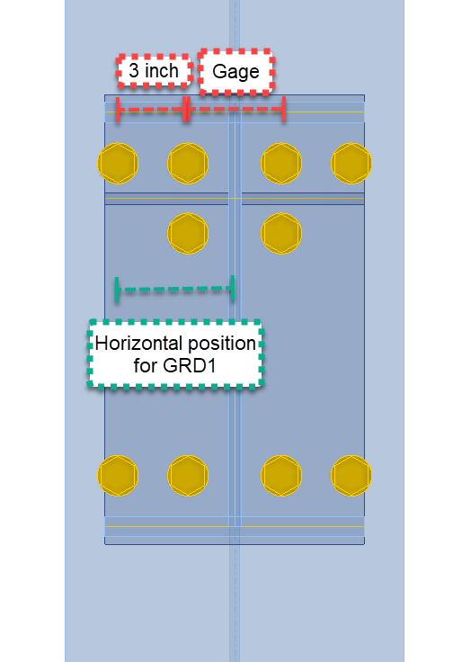
- P24= Direct input of position for GRD1
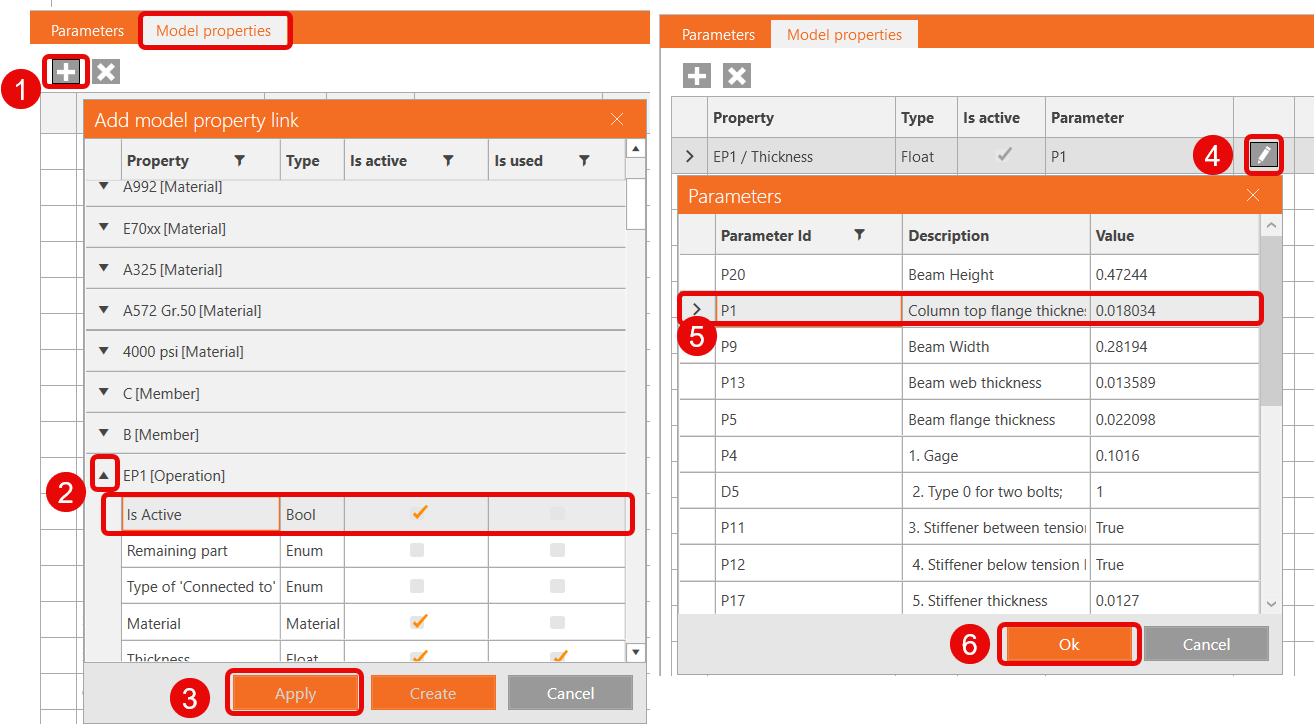
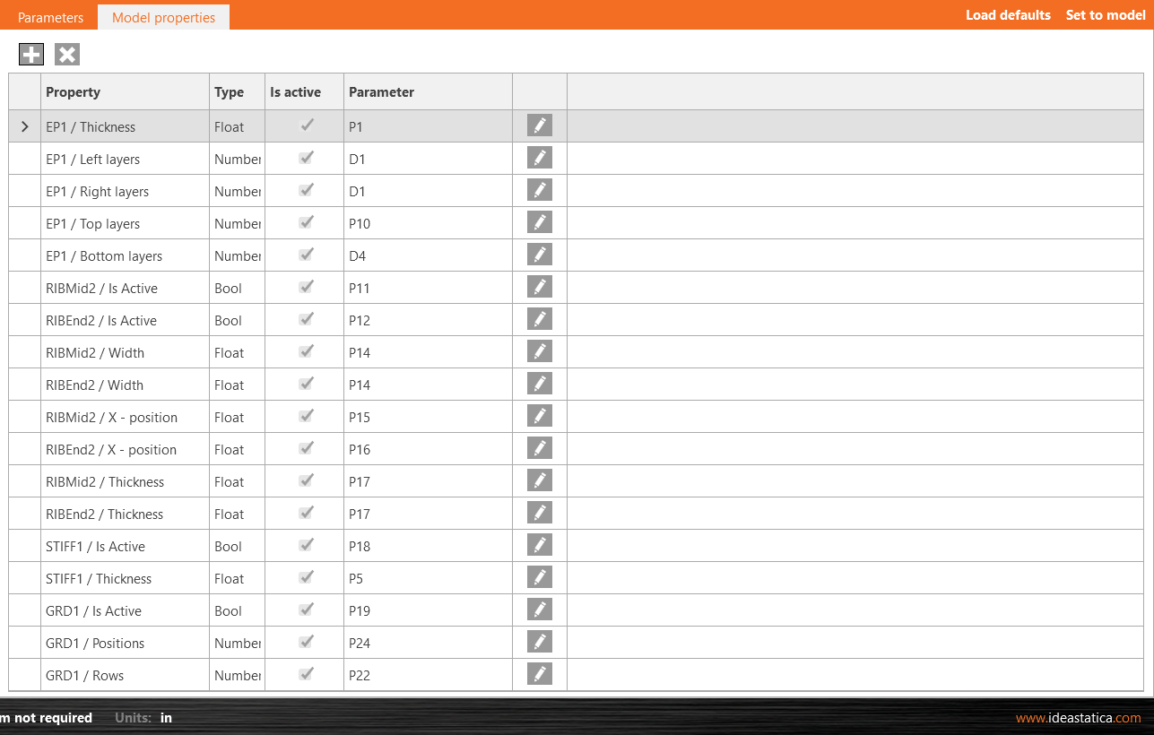
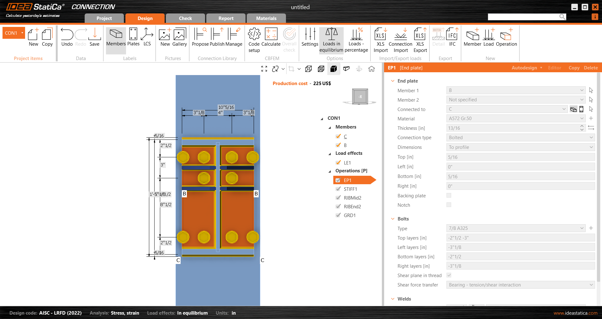
3 Model properties
Before the parameters can function, we need to relate them to their respective operation properties. Go to the Model Properties tab and add the following list of properties. Click on the "+" icon to open the Model property link window. Select the operation, click the dropdown menu to find the correct property, and click Apply.
Tip: Add all the model properties at once and after, click on the pencil to relate the parameter. Follow the below table as a guide.
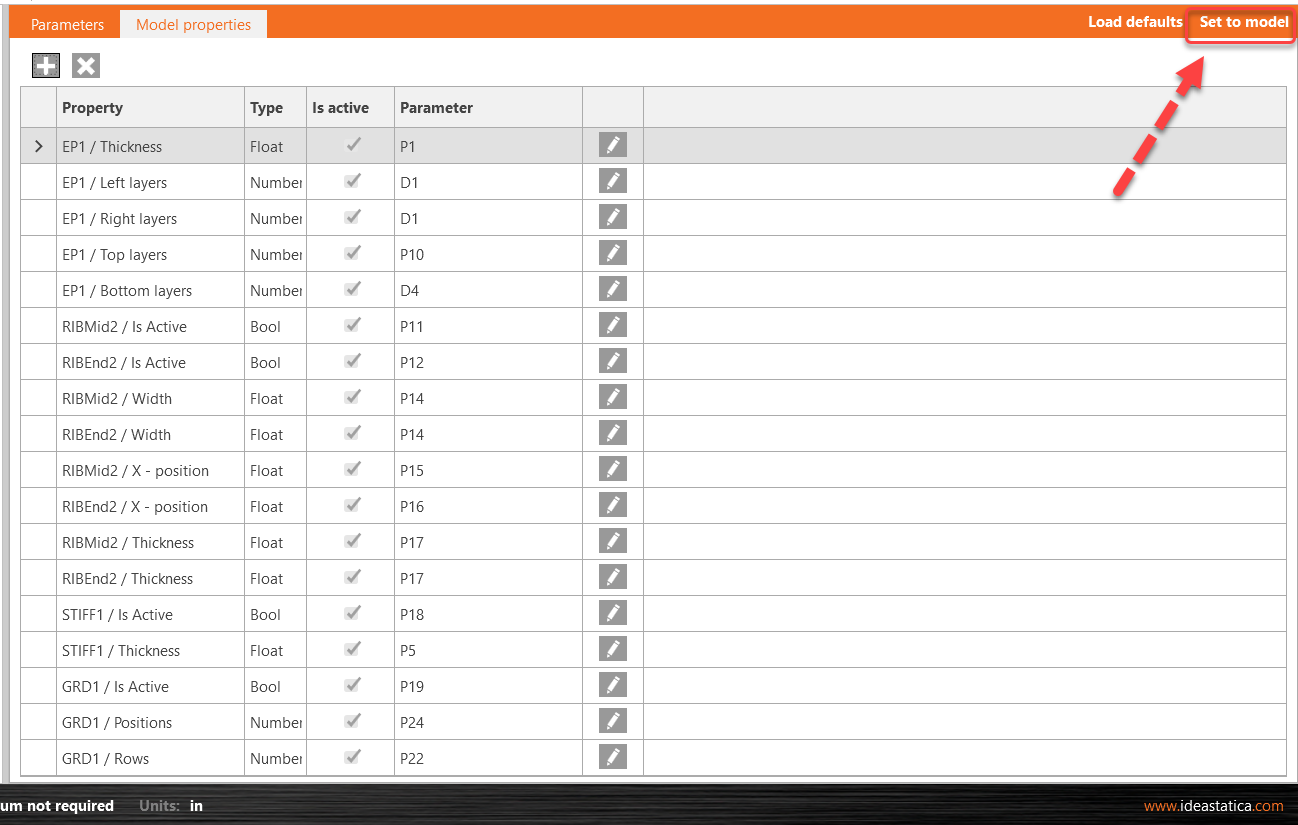
Once you add the model properties link to the parameters, click on Set to model, and review the changes on the operations.
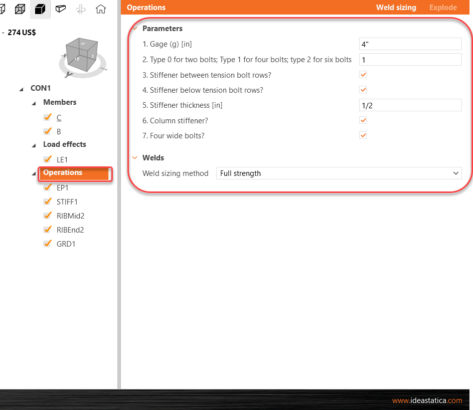
Lastly, you can review the visible parameters, Design tab>Click on the Operations line and see the parameters in the right side of the screen.
You can also test the parameters, change the gage, or uncheck one of the stiffener options.
4 Publish to Connection library
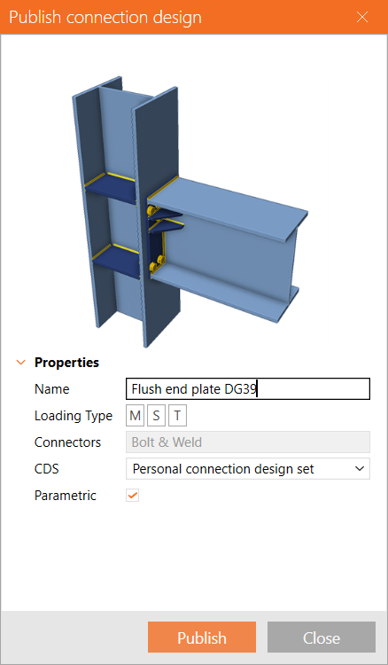
Go to the Connection Library, select Publish, a new window "Publish connection design" appears.
Enter a unique name for your new template, select your personal or company set and click on Publish. The variable Parametric is checked automatically.
5 Template usage
The template you created can now be used in similar joints. In the right bottom corner, there is a sign (P) for Parametric.
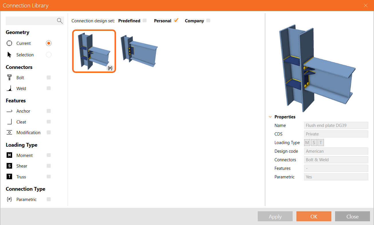
Even if you have not enabled the Developer tab, after applying this template to another joint, you will still be able to access the visible parameters, but all other items will be greyed out and won't accessible by the user
See below the finished model.
Parametric template for flush moment end plates
You have acquired the skills to utilize parameters, create parametric templates, and undertake fundamental parameter-related tasks.