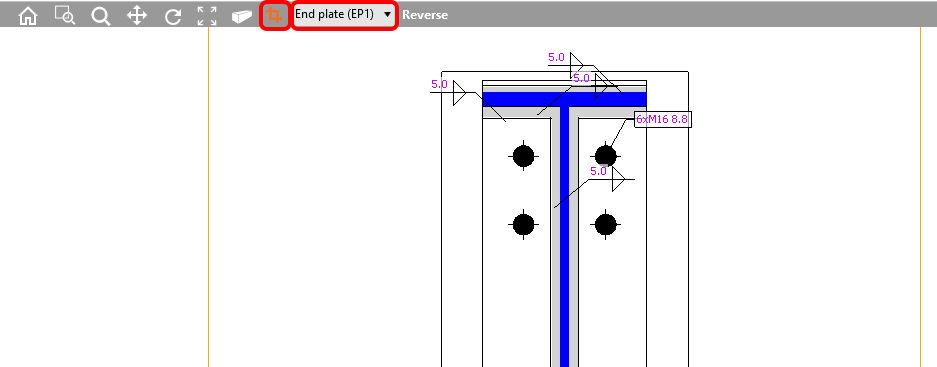
Section model view – drawings (“sketches”)
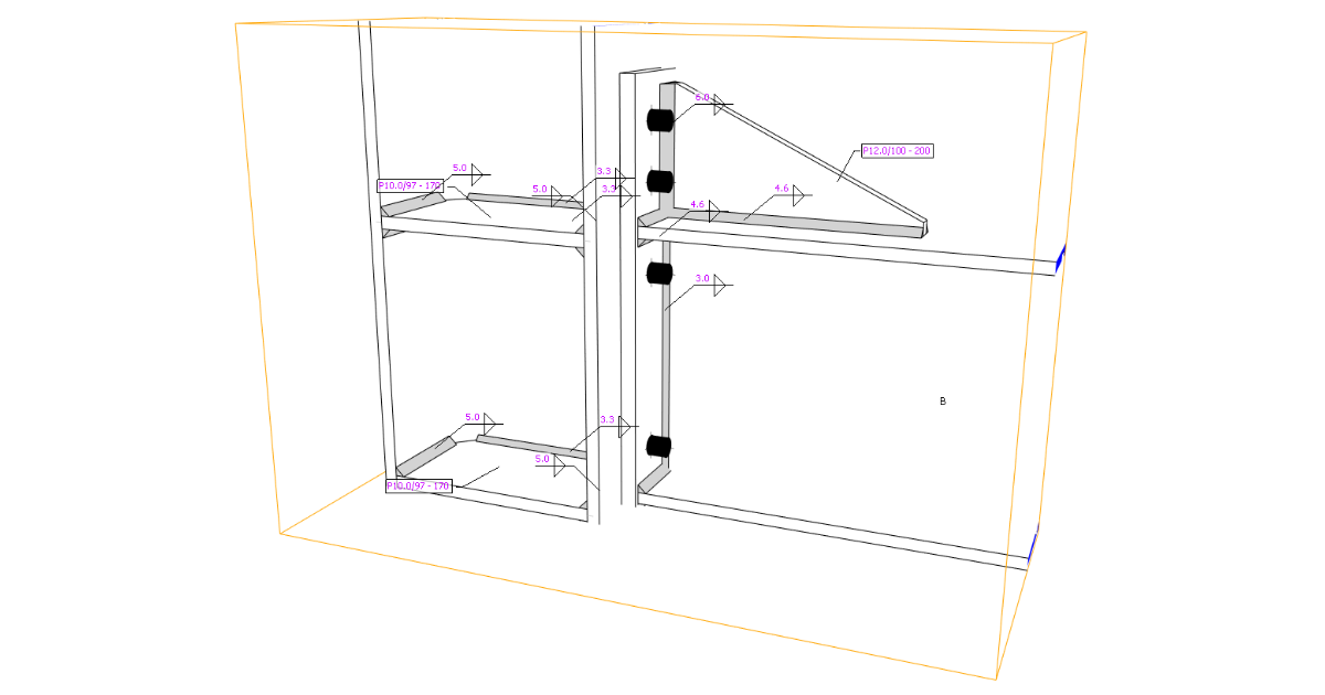
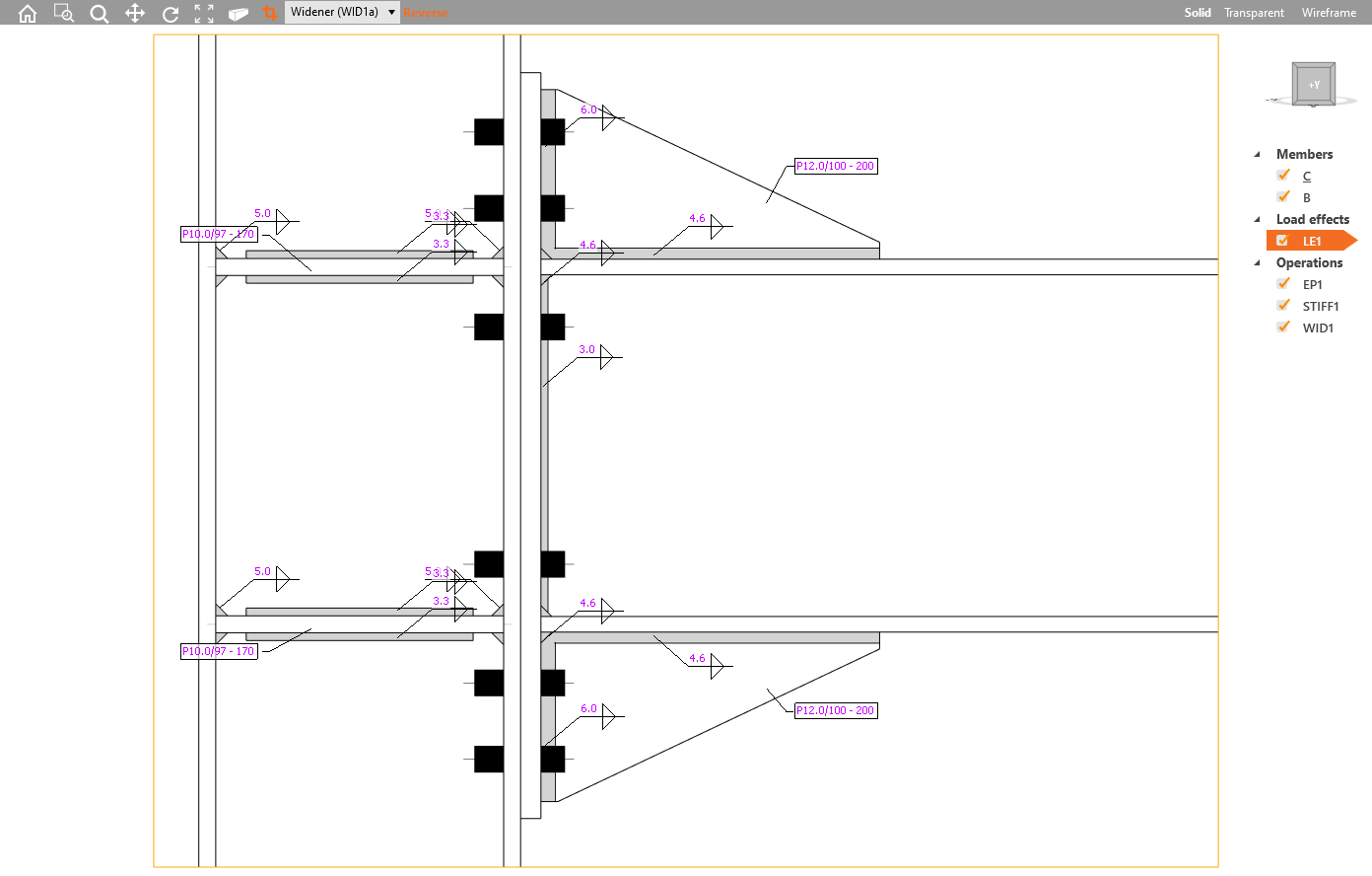
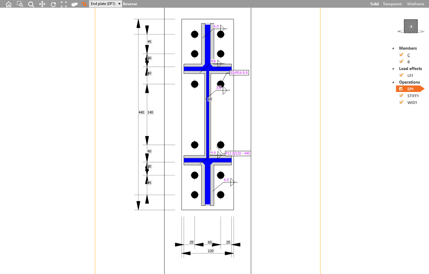
All structural engineers, designers, and detailers require clear visual outputs of their designs. That is why the possibility of drawings adjustments was a highly desired feature. Engineers want to generate “sketches”, detailers like to receive them, so they do not start the detailing from scratch. From now on, you can define and modify section models in the main 3D scene window.
Several section views can be defined, each of them must be attached to the plate, and the boundaries of the section or the section orientation can be modified.
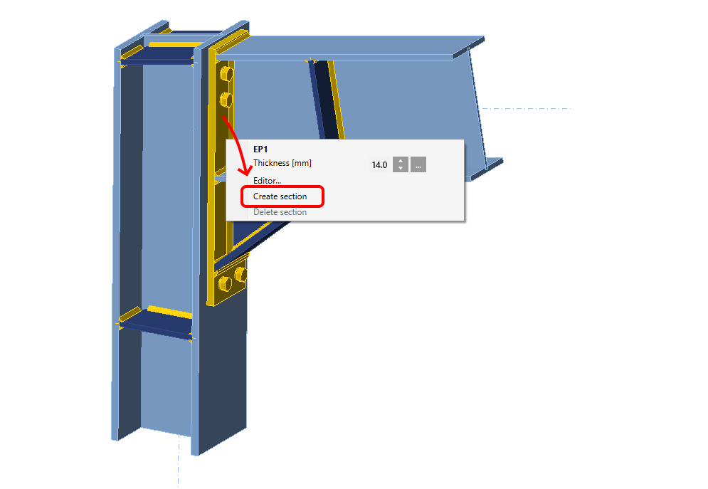
To add a new section to produce a drawing or sketch, select a plate in the connection model, and in the right-click menu select Create section. To delete it, select the plate and choose Delete section.
To exit the section view, click the icon Named section. You can access the section views afterward again using this icon and browse and modify all added sections in the menu.
Section model view can be printed to report or saved to a gallery for further usage.
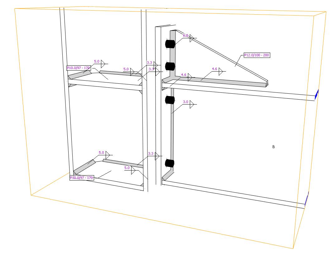
There is set an automatic generation of labels for welds and plates which describe the type and thickness of the weld and thickness/dimensions of the plate, respectively.
Weld labels and plate property label
This feature is available only in Enhanced version of IDEA StatiCa Steel


